International Journal of Scientific & Engineering Research, Volume 3, Issue 8, August-2012 1
ISSN 2229-5518
The Effect of Different Electrodes for The
Electrogenerative Recovery of Cobalt
Soh Wen Min, Afidah Abd Rahim, Norita Mohamed
Abstract—Cobalt was recovered electrogeneratively by using a batch cell. In this system, a spontaneous chemical reaction occurred where cobalt is reduced at the cathode and zinc is oxidized to produce a free flow of electrical energy without any external power supply. The performances of reticulated vitreous carbon (RVC) and porous graphite (PG) as cathodes were evaluated based on the time and percentage of removal in an electrogenerative cell. Cyclic voltammetry and polarization studies were conducted to study the characteristics of these cathodes for cobalt deposition. RVC performed better than PG for cobalt recovery as 99.9% of recovery was achieved in 120 minutes whereas for PG it was 80.8%. Based on the cyclic voltammograms, the cobalt deposited on RVC and PG underwent an oxida tion process to form cobalt oxides.
Index Terms—cobalt, electrogeneratively, spontaneous chemical reaction, RVC, PG, percentage of removal
—————————— ——————————
1 INTRODUCTION
ELECTROGENERATIVE processes possess great potential as an alternative to the conventional electrolytic treatment of industrial effluents. Recent studies show that it is effective in removing heavy metal pollutants such as copper, chromium and lead [1]. Its working mechanism is a spontaneous chemical reaction which produces a free flow of electrical current without any external power supply [2]. This property presents an opportunity for the electrogenerative process to treat dilute waste streams effectively since their treatment by electrolytic systems for dilute waste involves high operating costs and power consumption due to thermodynamics and kinetic limitations [3]. Moreover, the design and operation of an electrogenerative reactor are easy, safe and require low maintenance.
The most important component in an electrogenerative reactor is the electrode. Three dimensional electrodes are designed specifically to resolve the mass transport limitations faced by electrochemical reactors when the metal ion concentration decreases [4]. The concept is to reduce the metal at a cathode surface while maintaining high mass transfer rates. The three dimensional electrodes with its high surface area to volume ratio and high porosity are very well suited as cathodes in the reactor for the removal of ions from solution [5]. The choice of 3D electrodes used in this study is reticulated vitreous carbon (RVC) and porous graphite (PG). They were selected because they are made of carbon material which is chemically and electrochemically inert over a wide range of potentials and chemicals and also exhibit good electrical conductivity [6]. There are substantial literatures available regarding the application of three dimensional
————————————————
Corresponding author: Professor Norita Mohamed. School Of Chemical
Sciences, Universiti Sains Malaysia, 11800 Minden, Penang, Malaysia.
E-mail: mnorita@usm.my.
electrodes over the past few years. However, the purpose of this study is to assess 3D electrode technology in the electrogenerative removal system. The investigation encompasses polarization and cyclic voltammetry studies to characterize both the 3D electrodes before they were employed in the electrogenerative reactor.
Emphasis is placed on the removal of cobalt ions. The supply and demand for cobalt metal has heightened in recent years due to increasing global production for portable devices such as smart phones and tablet computers [7]. Improper disposal of industrial effluents containing cobalt results in water pollution. Over exposure to cobalt will incur irreversible damages to mankind and the ecosystem. Thus, the electrogenerative recovery process is a viable solution to the current situation.
2 EXPERIMENTAL
2.1 Voltammetric studies
Cyclic voltammetry was conducted in a 15 mL Pyrex cell vial with a conventional three electrode system where RVC (RVC 80 ppi, The Electrosynthesis. Co) and PG (PG-25, National Electrical Carbon Products, Inc) served as working electrodes, Ag/AgCl as reference electrode and platinum wire as counter electrode. An eDAQ EA 161 potentiostat connected to a 61 e–corder 410 (4–channel recorder) equipped with EChem software was used to carry out the electrochemical measurement. The solution used was 500 mg L-1 cobalt in 0.1 M sodium chloride solution. All electrolytes were prepared from analytical grade reagents using 18 MΩ cm deionised water. The catholyte was prepared from CoCl2.6H2O (QRëC Tm) with NaCl (System ®) as supporting electrolyte.
2.2 Polarization studies
The electrogenerative cell polarization under the influence of different cathodes was accomplished by loading the system with maximum resistance initially and then
IJSER © 2012
http://www.ijser.org
International Journal of Scientific & Engineering Research, Volume 3, Issue 8, August-2012 2
ISSN 2229-5518
gradually decreasing until it was short-circuited. The variable resistance was adjusted with a decade resistance box (Time Electronic Ltd. 1051). Three replicates of polarization curves were recorded to ensure reproducibility. For each experiment, three minutes were required for the cell to equilibrate before the cell current and cathode potential versus saturated calomel electrode (SCE) readings were recorded.
2.3 Cell configuration and experimental conditions
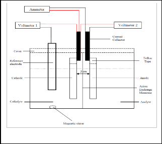
Fig. 1 shows the schematic diagram of a batch reactor. The batch reactor is made out of Plexiglass containing 2 electrolyte compartments of dimensions 5.5 cm
× 5.5 cm × 8.0 cm separated by anion exchange membrane Neosepta® AM-01(Tokuyama Corp). Both cathode and sacrificial zinc anode (> 99% purity, R&M chemicals) were attached to copper strips which function as current collectors using Teflon tape. The dimensions of the cathodes and anode used are 2.0 cm × 4.5 cm × 0.3 cm and 2.0 cm × 4.5 cm × 0.05 cm respectively. The current collectors were connected by external conducting wires to Sanwa Digital Multimeters CD800a to complete the circuit. The catholyte compartment was filled with 100 mL of 100 mg L-1 Co in 0.1 M NaCl whereas the anolyte compartment was filled with 100 mL of
0.1 M NaCl. The catholyte was deoxygenated with nitrogen for 30 minutes prior to any experiments and maintained under that atmosphere with a flux of nitrogen above the electrolyte surface. All the experiments were carried out at room temperature. The concentrations of cobalt and zinc in the batch reactor were monitored by successive sampling of the catholyte and anolyte every 30 minutes and then analyzed with a Perkin Elmer Analyst 200 Atomic Absorption Spectrometer. Surface morphology of the cobalt deposits from the recovery process was analyzed using a Leo Supra 50 VP scanning electron microscope (SEM) whereas elemental analysis of the deposits on the cathode was determined by Oxford INCA 400 energy dispersive X-ray spectrometer (EDX).
3 RESULTS AND DISCUSSION
3.1 Voltammetric Studies
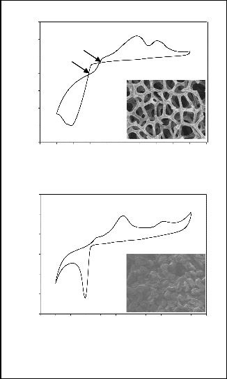
Fig. 2 shows a set of cyclic voltammograms obtained from both RVC and PG within the range of +600 to -1400 mV vs Ag/AgCl at a scan rate of 5 mV s-1. Both voltammograms agree with a typical triangular sweep voltammetry of cobalt deposition on carbon electrodes [8]. The voltammograms consist of two main features. First is the virtually zero cathodic current on forward scan until the onset of nucleation of cobalt (-0.78 V for RVC and -0.70 V for PG) follows by a rapid rise of the current on the forward scan once nucleation or reduction begins [9]. These features are to be expected for a system involving nucleation and growth of the metal phase on a carbon electrode. However, a difference is observed between the reductive peak currents of RVC and PG with the values being 6.123 mA cm-2 and 2.891 mA cm-2 respectively. A higher current is produced with RVC during cobalt reduction compared to that with PG. This behavior implies that extra energy will be needed by PG to reduce cobalt in an electrogenerative cell.
0.004
0.002
Ec
0.000
n
-0.002
-0.004
-0.006
-0.008
-0.010
-1.4 -1.2 -1.0 -0.8 -0.6 -0.4 -0.2 0.0 0.2 0.4 0.6
E vs Ag/AgCl / V
(a)
0.004
0.002
0.000
-0.002
-0.004
-0.006
-0.008
-1.4 -1.2 -1.0 -0.8 -0.6 -0.4 -0.2 0.0 0.2 0.4 0.6 0.8
E vs Ag/AgCl / V
(b)
Fig.1. Experiment setup of the batch cell.
Fig. 2. Voltammetric curves and SEM images (50×
magnification) for cobalt deposition on (a) RVC and (b) PG
IJSER © 2012
http://www.ijser.org
International Journal of Scientific & Engineering Research, Volume 3, Issue 8, August-2012 3
ISSN 2229-5518
Another difference observed is the two distinct crossovers between cathodic and anodic current on the reversing sweep with RVC which is shown in Fig. 2(a). The more cathodic crossover denoted as En (-0.80 V) is the nucleation potential which corresponds to the formation of a new phase in the nucleation process. The second crossover is found at -0.66 V denoted as overcrossing potential Ec. The increase of potential from En to Ec is related to the change in the concentration of cobalt on the electrode surface as the deposition process progresses [10]. The voltammogram of PG does not display any crossover. Despite that, according to Cui et al. [9], as long as the cathodic reversing potential is more positive than the cathodic peak potential, a growth- loop occurs. The absence of crossovers is because of the compact surface area of PG as showed in the inset of Fig.
0.6
0.4
0.2
0.0
-0.2
-0.4
-0.6
-0.8
-1.0
RVC PG
0.0 0.5 1.0 1.5 2.0 2.5 3.0
j/ mA cm-2
2(b). With its open-pore foam material of honeycomb structure (inset of Fig. 2(a)), the current is able to penetrate through the RVC resulting in crossovers during the nucleation process and higher reductive peak currents [11]. The anodic peaks observed in both RVC and PG is likely to correspond to the oxidation of different cobalt phases. Thus, it can be concluded that the deposition process on RVC and PG occurred via a similar nucleation mechanism as shown in the following equations.
Cobalt ion is reduced initially.
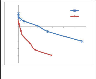
Fig. 3. Cathodic polarization curves for 100 mg L-1 Co in 0.1 M NaCl on RVC and PG
3.3 Cobalt removal using a batch reactor
An electorogenerative system with the cell configuration of Zn|ZnCl2 (1.0M)||CoCl2 (1.0M)| RVC/PG [13] was constructed. The overall reaction for reduction of Co2+ to Co0 on the RVC and PG surfaces can be described by the following half cell equations.
(1)
Due to the influence of oxygen reduction in catholyte, cobalt hydroxide is formed.
(2)
(3)
The cobalt hydroxide is then further oxidised to form cobalt
oxide.
(4)
(5)
(6) (7)
3.2 Polarization studies
Polarization tests have been done to study the performance of the electrogenerative cell with different cathodes. As illustrated in Fig. 3, the plot of cathode potential vs current density for PG is more polarized than RVC. At current density of 1 mA cm-2, there is a significant decrease in cathode potential with 852 mV for PG compared to the 347 mV for RVC. A maximum current density as high as 2.83 mA cm-2 is achieved with RVC while PG only produces a current density of 1.47 mA cm-2. Previous studies have reported that a cathode with smaller polarization and higher achieved current density has a better recovery rate and percentage [2], [3], [12]. Moreover, the less polarized RVC with its high current density in this study indicates the good electrical conductivity property of RVC. Thus, RVC is recommended as the electrode of choice for the electrogenerative cell to remove cobalt.
At RVC, the following reactions take place.
Anode: (8) Cathode: (9)

Overall: (10)
At PG, the following reactions take place.
Anode: (11)

Cathode: (12) Overal: (13)
With these values of for both cathodes, the state of spontaneity for the redox process under the influence of different cathodes is explained by the free energy change F. Free energies of -389.8 kJ mol-1 and -351.2 kJ
mol-1 are obtained respectively for RVC and PG. The negative free energy values prove the spontaneity of the deposition reaction. Meanwhile, the larger magnitude of free energy for RVC suggests that the reaction on RVC is more favourable compared to PG. Since the spontaneity of the process has been established, the performances of RVC and PG are then evaluated based on rate of reaction and current efficiency, CE which is given by the following formula [13].

(14) The final percentage of cobalt recovered at RVC was
99.9% after 120 min whereas at PG, the final percentage was
80.8 %. The current efficiency for RVC was higher than PG, which was 65.1 % compared to 52.7 % for PG. Hundred percent current efficiency was not achievable for both
IJSER © 2012
http://www.ijser.org
International Journal of Scientific & Engineering Research, Volume 3, Issue 8, August-2012 4
ISSN 2229-5518
cathodes because the system was affected by parallel reactions such as hydrogen evolution, oxygen reduction and cobalt dissolution [14]. From a kinetic point of view, RVC performed better since its cobalt removal half life, t1/2 was 17 min compared to 41 min of PG.
3.4 Surface Analysis
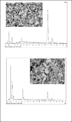
As seen in Fig. 4, the cobalt deposits appeared to be aggregated uniformly in a crystalline form on RVC and granular form on PG. It is believed to be cobalt oxide which was reflected by the presence of oxygen observed in the following EDX spectra.
(a)
(b)
Fig. 4. SEM images (5000× magnification) and EDX
spectra of the cobalt deposits on (a) RVC and (b) PG.
4 CONCLUSION
An electrogenerative system coupled with RVC has shown promising performance with a free energy of -389.9 kJ. The percentage removal was satisfactory as 99.9 % removal was achieved. RVC is the more suitable cathode material in this electrogenerative system.
ACKNOWLEDGEMENTS
This study was supported by research grants provided by Ministry of Higher Education Malaysia under Research University (RU) Grant no. 1001/PKIMIA/814125 and Institute of Postgraduate Studies Universiti Sains Malaysia (308/AIPS/415401).
REFERENCES
[1] C.Y. Yap and N. Mohamed, “Electrogenertive Processes for Environmental
Application,” Clean-Soil Air Water, vol. 36, no. 5-6, pp. 443-452, Apr. 2008.
[2] C.Y. Yap and N. Mohamed, “An Electrogenerative Process for The Recovery of Gold from Cyanide Solutions,” Chemosphere, vol. 67, no. 8, pp. 1502-1510, Apr. 2007.
[3] Y.P. Hor and N. Mohamed, “Removal and Recovery of Copper via A
Galvanic Cementation System Part I: Single-pass Reactor,” J. Appl. Electrochem., vol. 33, no. 3-4, pp. 279-285, 2003.
[4] E.J. Podlaha and J.M. Fenton, “Characterization of A Flow-by RVC Electrode Reactor for The Removal of Heavy Metals from Dilute Solutions,” J. Appl. Electrochem., vol. 25, no. 4, pp. 299-306, 1995.
[5] D. Pletcher, I. Whyte, F.C. Walsh, and J.P. Millington, “Reticulated Vitreous
Carbon Cathodes for Metal Ion Removal from Process Streams Part II: Removal of Copper(II) from Acid Sulphate Media,” J. Appl. Electrochem., vol.
21, no. 8, pp. 667-671, 1991.
[6] P. Marco, S. Carlo, and C. Giacomo, “Electrochemical Remediation of Copper (II) from an Industrial Effluent Part II: Three-dimensional Foam Electrodes, “ Resour. Conserv. Recy., vol. 27, no. 4, pp. 299-307, Oct. 1999.
[7] E. M. Garcia, J.S. Santos, E.C. Pereira, and M.B.J.G. Freitas, “Electrodeposition of Cobalt from Spent Li-ion Battery Cathodes by The Electrochemistry Quartz Crystal Microbalance Technique,” J. Power Sources, vol. 185, no. 1, pp.
549-553, 2008.
[8] A.B. Soto, E.M. Arce, M. Palomar-Pardave, and I. Gonzalez, “Electrochemical Nucleation of Cobalt onto Glassy. Carbon Electrode from Ammonium Chloride,” Electrochim. Acta, vol. 41, no. 16, pp. 2647-2655, 1996.
[9] C.Q. Cui, S.P. Jiang, and A.C.C. Tseung, “Electrodeposition of Cobalt from
Aqueous Chloride Solutions,” J. Electrochem. Soc., vol. 137, no. 11, pp. 3418-
3423, Nov. 1990.
[10] L.H. Mendoza-Huizar, J. Robles, and M. Palomar-Pardave, “Nucleation and Growth of Cobalt onto Different Substrates: Part II. The Upd-opd Transition onto A Gold Electrode,” J. Elecctroanal. Chem., vol. 545, pp. 39-45, Mar. 2003
[11] J.M. Friendrich, C. Ponce-de-Leon, G.W. Read, and F.C. Walsh, “Reticulated
Vitreous Carbon as An Electrode Material,” J. Electroanal. Chem., vol. 561, pp.
203-217, Jan. 2004.
[12] W.X. Tan and N. Mohamed, “Electrogenerative Removal of Cobalt from Sulphate Medium Using a Batch Reactor,” Clean-Soil Air Water, vol. 39, no. 5, pp. 460-466, May. 2011.
[13 W.X. Tan, M.A. Hasnat, N.H.M. Ramalan, W.M. Soh, and N. Mohamed,
“Influence of Flow Rates on The Electrogenerative Co2+ Recovery at A Reticulated Vitreous Carbon Cathode,” Chem. Eng. J., vol. 189-190, pp. 182-
187, May. 2012.
[14] E.M. Garcia, H.A. Tarôco, T. Matencio, R.Z. Domingues, J.A.F. Santos, and M.B.J.G. Freitas, “Electrochemical Recycling of Cobalt from Spent Cathodes of Lithium–ion Batteries: Its Application as Coating on SOFC Interconnects,” J. Appl. Electrochem., vol. 41, no. 11, pp. 1373-1379, 2011.
IJSER © 2012
http://www.ijser.org
International Journal of Scientific & Engineering Research, Volume3, Issue 8, A ugust-2012 5
ISSN 2229-5518
IJSER 2012 http /lwww.11 Ser.ora
International Journal of Scientific & Engineering Resea rch, Volume 3, Issue 3, March-2012 6
ISSN 2229-5518
IJSER 20 12
http 1/www iiser ora