International Journal of Scientific & Engineering Research, Volume 4, Issue 10, October-2013 1223
ISSN 2229-5518
Temperature Augmentation in Compact Solar
Thermal System
Deb,S.K1 & Sarma. B.C2
1Professor in Mechanical Engineering Department Assam Engineering College, Guwahati, India email: sudipkumardeb@Gmail.com
2Research Scholar, Assam Engineering College, Guwahati, India
email: bcsbinoy@Gmail.com
Abstract: In solar thermal concentrators using thin metallic reflector sheet as the concentrator surface, the fraction of net solar radiative heat absorbed by the collector is dissipated to the surrounding without use through it’s exposed surfaces & the supporting structure. A simple compact solar thermal device with the recovery of solar radiative heat absorbed by the concentrator is discussed here for it’s effect on
thermal performance. The concentrator is placed on a spiral housing of heat exchanger pipes at the insulated rear end of the collector with
it’s focal image at the aperture plane with a glass cover is studied here.
Keywords: Polygeneration, Insolation, Focal Image, Sensible heat
1.0 Introduction
Conventional paraboloid dish concentrator uses thin metallic reflector sheet, synthetic stretchable reflecting membrane, glass mirror facets and other such modern improvised reflecting materials. As referred in Figure1:, a paraboloid dish surface is developed by the integration of a few lunes of thin metallic reflector sheets geometrically prepared by Gore’s method to get the maximum possible point focus at it’s aperture plane eliminating possible surface error. This component is placed in a spiral housing of heat exchanger pipes at the rear surface of the collector with an insulated cover & the whole assembly is pivoted on a hollow cylindrical support through another short cylinder for necessary manual orientation for tracking. The receiver at the aperture is placed in the same support of the glass cover to reduce the extra supporting structural weight. The aperture glass cover is expected to serve the purpose in the same way as in case of a flat plat collector besides protection from weathering to sustain good reflectivity.
The effect of heat recovery components & insulation is investigated through enhanced temperature rise in the heat exchanger water and air temperature in the enclosed volume bounded by the insulated cover & the rear surface of the metallic concentrator. Developing a compact solar thermal design of reduced weight & cost with maximum possible heat accumulation per unit aperture area with waste heat recovery is the motivation behind this study.
Early in 1989, a study conducted by Chen Xiaofu at el.[1] to develop the most popular point focusing solar cooker in China to accumulate maximum solar flux, compensating intensity loss due to the inclination of solar altitude angle. For a shorter focal length image formation with a concentration ratio of higher rim angle was studied by Kenef S, Schmidt at el. [2] & a two stage optical design of concentrator (TERC) with variable focal length was proposed by Robert P. Friedman at el.[3]. N.D. Koushika at el.[4] proposed for a deep dish collector design with ideal image formation where cavity receiver performance was investigated.
Regarding effective concentrator surface development, Aluminium-polymer-laminated steel reflector, suggested by Maria Brogren at el.[10] & the test report study on at the Jet Propulsion Laboratory, California, USA, and Sandia National Laboratories, Albuquerque, New Mexico[6] on glass mirror facets etc discussed about the effects of specific weight of the reflector, non retention of optical property even as using of any protective layer (e.g. polyethylene terephthalate) on aerial exposure. In using glass mirrors, delamination crack & weight, rigidity to deform were spotted as major drawbacks in the above study. Increasing of local concentration ratio by increasing rim angle beyond 800 affects the width of focal image & distortion as depicted by Evan at el.[7]. In our proposed model, the focal image formed at the aperture plane subtends a rim angle beyond maximum limit of 800 giving rise to a focal image of distorted wider periphery, but improvement of the image profile without compromising the
IJSER © 2013 http://www.ijser.org
International Journal of Scientific & Engineering Research, Volume 4, Issue 10, October-2013 1224
ISSN 2229-5518
higher concentration ratio is another objective of our study. In this study the aforesaid investigations are considered.
2. Model performance with graphical analysis.
2.1 Bench model results:
The bench model described earlier, was tested on sunny days at Guwahati (North East India) with Φ(Latitude) =
26.1838° N (Altitude = 91.7633 E ) with variable
Ta = Surrounding (ambient) temperature(0 c)
Two = Outlet temperature of water in the heat exchanger(0 c) Thao = Outlet temperature of air (0 c)
Tf = Receiver temperature at the focal point(0 c)
Cp = Specific heat of water at constant pressure (KJ/Kg.0K) Aa = Aperture area of the collector (m2)
Ra = Aperture radius (m)
Ib = Radiative solar flux (W/m2)
ambient conditions and the results were analyzed accordingly.
h f = Sensible or liquid heat of water per kg of mass on preheating by the heat recovery component (KJ/kg)
dh = (H-h f),The net heat required to bring liquid heat to the saturation point at constant pressure per kg of mass (KJ/kg) H = The enthalpy of water at saturated temperature (1000c) under atmospheric pressure i.e 419.1(KJ/kg)
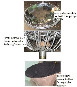
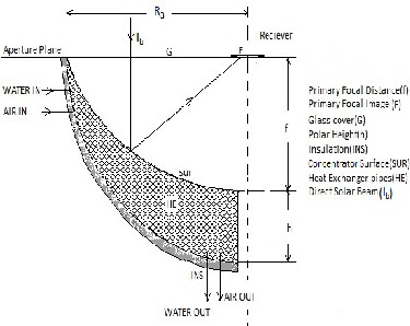
Figure 1(a): Geometrical design of the system Figure 1(b): Experimental bench model
Block diagram showing Temperature status of the proposed model.

Ta
Air Heater (Thao)
( Thao - Ta )
Load
(Dryer, Boiler, Domestic Heat etc.)
Figure 2:
IJSER © 2013 http://www.ijser.org
International Journal of Scientific & Engineering Research, Volume 4, Issue 10, October-2013 1225
ISSN 2229-5518
As in the Figure1:, thin steel sheet of high reflectivity is used for the concentrating surface and aluminium pipes for the heat exchanger. The efficiency of the system may be


expressed as η = �∑𝑚𝐶� [dT/dt] where �∑𝑚𝐶� is constant for
like Milk Pasteurization, Crop Drying, Food Processing, Textile, laundries, Domestic Heat, Washing & Cleaning, Community Cooking etc need process heat in the temperature range of 300c to 2500c.The heat accumulation
𝐼𝑏 𝐴𝑎
𝐼𝑏 𝐴𝑎
rate at the focal point may fulfill the aforesaid demand but it
a particular thermal system with an average radiative solar
intensity, considering ∑𝑚𝑐 as the summation of the products
of respective mass & specific heats interacting heat transfer.
Therefore the system efficiency under transient condition may be considered as the function of the rate of temperature rise only & temperature rise is the dominant factor for the efficiency of the system. The heat transfer to the specific load may be a drying unit using hot air, process heat using hot water or steam. Very often only the latent heat is consumed for multiple utility. Under such situation a single heating system may be envisaged where variable heating facilities with multiple qualitative & quantitative measures can be achieved for several processes. Several applications
2.2 Bench Model Experimental Results:
will be a standalone mode for a particular intensity of solar radiation. Therefore as stipulated in the figure2: , the convective heat from the hot surfaces of the exchanger pipes acquired by the air entrapped in the space bounded by the collector rear surface & the insulated cover is enhanced by the glass cover at the aperture in the same way that of a single cover flat plate collector. The water in the heat exchanger is preheated by the aforesaid heat recovery system up to some extent for reducing the net heat required for saturation. After achieving the saturation temperature, the residual heat accumulated by the receiver at the focal point will give out the necessary quality of steam under regulated thermal conditions at a higher rate of delivery.
Measuring tools used are:(i)Digital Thermometer: Range:-
200 to 1000 0 c (ii) Infra Red Thermometer (TESTO Make,
Table1:
UK). All parameters are for 10 minutes for stagnation in every 30 minutes interval.


Time Date Ta T wo Thao Tf Thao / Ta Two / Ta Ambient Conditions
11.00 hrs 25-04-13 28.20 70.80 49.00 107.8 1.74 2.51 wind flow
11.30 hrs 25-04-13 29.40 76.00 50.00 108.00 1.70 2.59 wind flow, sunshine interruption
12.00 hrs 25-04-13 32.40 78.00 50.00 115.60 1.54 2.41 wind flow, sunshine interruption
12.30 hrs 25-04-13 31.50 89.70 55.00 115.00 1.75 2.84 wind flow, cloudy
13. 00 hrs 25-04-13 33.50 90.50 56.00 163.90 1.67 2.70 clear sky, wind flow
13.30 hrs 25-04-13 34.00 91.80 56.50 170.70 1.66 2.70 clear sky, minimum wind
14.00 hrs 25-04-13 33.50 92.70 57.70 177.20 1.72 2.78 clear sky, minimum wind
11.00 hrs 26-04-13 28.9 81.50 51.00 100.80 1.76 2.82 wind flow
11.30 hrs 26-04-13 28.4 90.00 50.30 93.00 1.77 3.17 wind flow, sunshine interruption
12.00 hrs 26-04-13 33.40 91.30 56.00 115.10 1.68 2.73 wind flow, unsteady focal image
12.30 hrs 26-04-13 32.50 90.40 54.40 118.00 1.67 2.78 wind flow
13.00 hrs 26-04-13 33.00 89.70 55.00 141.80 1.66 2.72 clear sky, wind flow
13.30 hrs 26-04-13 34.00 92.00 57.00 170.60 1.68 2.70 clear sky, moderate wind
14.00 hrs 26-04-13 33.8 92.80 56.90 175.10 1.68 2.74 clear sky, minimum wind
180
180
Ambient Temperature
160 Outlet Water Temperature
Outlet Air Temperature
Ambient Temperature
160 Outlet Water Temperature
Outlet Air Temperature
140
Focal Image Temperature
140
Focal Image Temperature
120
120
100
100
80 80
60 60
40 40
20
11 11.5 12 12.5 13 13.5 14
Time(Hr)
20
11 11.5 12 12.5 13 13.5 14
Time(Hr)
IJSER © 2013 http://www.ijser.org
International Journal of Scientific & Engineering Research, Volume 4, Issue 10, October-2013 1226
ISSN 2229-5518
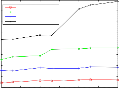
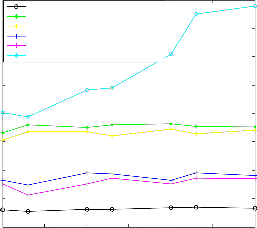
Figure 3(a): Temperature -vs- Time on 25-04-13 Figure 3(b): Temperature -vs- Time on 26-04-13
Table 2:


Time Ta T wo1 Thao1 Two2 Thao2 Tf hf dh Remarks
11.00 hrs 32.50 86.50 53.00 Temperature reading 100.80 363.0 56.1
11.30 hrs 31.00 92.00 49.40 with the rear insulator 97.00 385.4 33.7 All readings taken
12.00 hrs 32.00 90.30 58.00 cover in place 115.10 379.0 40.1 on 21-05-13 with
12.30 hrs 32.00 92.00 57.40 118.00 385.4 33.7 an average climatic
13.00 hrs 33.00 92.80 53.00 141.80 389.0 30.1 condition as earlier
13.30 hrs 34.00 91.00 58.00 170.60 381.1 38.0 with higher solar
14.00 hrs 33.00 90.60 56.40 175.10 379.0 40.1 intensity,,
11.00 hrs | 32.00 | Temperature reading | 81.20 | 50.20 | 100.00 | 340.0 | 79.1 |
11.30 hrs | 31.00 | without the rear | 87.00 | 42.40 | 98.00 | 364.3 | 54.8 |
2.00 hrs | 33.00 | insulator cover | 87.30 | 50.40 | 118.10 | 364.6 | 54.5 |
12.30 hr | 33.10 | | 84.30 | 54.50 | 118.00 | 352.0 | 67.1 |
13.00 hrs | 33.80 | | 89.00 | 50.50 | 142.00 | 372.7 | 46.4 |
13.30 hrs | 34.00 | | 85.60 | 54.50 | 170.00 | 359.0 | 60.1 |
14.00 hrs | 33.60 | | 88.30 | 54.20 | 176.30 | 370.0 | 49.1 |
180
160
140
Ambient Temperature
Outlet Water Temperature with Insulation Cover Outlet Water Temperature without Insulation Cover Outlet Air Temperature with Insulation Cover
Outlet Air Temperature without Insulation Cover
Focal Image Temperature
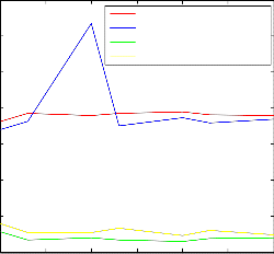
700
600
500
Sensible heat with insulation Sensible heat without insulation Prehaeting effect with Insulation Prehaeting effect without Insulation
120
400
100
80
300
200
60
40 100
20
11 11.5 12 12.5 13 13.5 14
Time(Hr)
0
11 11.5 12 12.5 13 13.5 14
Time(Hr)
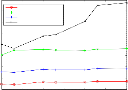
Figure 4(a): Temperature -vs- Time Figure 4(b): Enthalpy rise -vs- Time
Comparative graphical representation on Temperature & Enthalpy Rise with & without rear insulation
Comparative statement on average temperature readings:
Date | Average Temperature Readings(0 c) | Remarks |
Date | Ta | Two | Thao | Tf | Two / Ta | Thao / Ta | Remarks |
25-04-13 | 31.8 | 84.2 | 53.4 | 136.8 | 2.65 | 1.68 | With rear collector surface insulation |
26-04-13 | 32.0 | 89.6 | 54.3 | 130.6 | 2.80 | 1.69 | With rear collector surface insulation |
21-05-13 | 32.5 | 90.7 | 55.0 | 132.0 | 2.84 | 1.72 | With rear collector surface insulation |
21-05-13 | 32.9 | 86.1 | 51.0 | 132.0 | 2.70 | 1.60 | Without rear collector surface insulation |
IJSER © 2013 http://www.ijser.org
International Journal of Scientific & Engineering Research, Volume 4, Issue 10, October-2013 1227
ISSN 2229-5518
3.0 Observations:
(i)From the temperature-time curves of the bench model experiment at Figure3(a): & Figure3(b):, it is found that there is always an increase in temperature for outlet air & water, sharing the absorbed heat by the reflector sheet. The
7% rise in average temperature in heat exchanger water using rear collector surface insulation predicts the opportunity reparation of convective heat loss. . (ii)In reference to the Figure 4(a): , the rise in temperature with insulation is higher than without insulation of the rear end of the collector.
(iii)The preheating effect of water in the heat exchanger with the rise in sensible heat from the heat recovery unit with insulation is higher than without insulation of the rear collector surface. Further it may be seen that less heat is needed for achieving the saturation point at constant atmospheric pressure with insulation. As a result the supply rate of steam, hot water, hot air etc will be more. (iv)The ratio of outlet water temperature to the ambient temperature is found higher than that of the hot air to ambient temperature which can be explained due to the variation of effective heat transfer surface area and higher conductive heat transfer rate to the water than that of air due to convective and small extent of radiative heat transfer to the air.
4.0 Discussion: It seems that the fraction of the absorbed solar irradiative heat flux shared by the air & water can be regulated by improvising the effective surface area of the heat exchanger pipes & that of the air passage. The flow rates were not regulated for air & water, rather some steady, instantaneous observations were made. Therefore after saturation point, the qualitative observation of evaporation is
References:
[1] Chen Xiaofu at el. Rural Energy Department, China.
[2] Kenef S, at el. Proceedings of Solar World
Congress (ISES), Perth, 1983
[3] Robert. P. Friedman at el., Center for Energy and Environmental Physics, Jacob Blaustein Institute for Desert Research, Israel.
[4] N.D. Kaushika, K.S. Reddy Centre for Energy
Studies, Indian Institute of Technology Delhi.
[5] Maria Brogrena at el.”Optical properties, durability, and system aspects of a new aluminium- polymer-laminated steel reflector for solar concentrators”, Uppsala University, Sweden.
beyond the scope of this study. The receiver design for regulating the parameters will be much easier to get necessary quality of steam as per available maximum temperature.
5.0 Conclusion:
As expected, the recovery of absorbed heat by the reflector sheet through conduction at the recovery unit i.e. heat exchanger assembly, as a supplement to the receiver to increase the rate of thermal output which is the most affirmative result of this study. The saturation temperature augmentation on preheating the water by the heat recovery system makes it possible to increase the latent heat absorption rate from the focal image temperature to provide the necessary input to a load at a higher rate where the latent heat is used as the process heat. System works as a Polygenerative system giving out three products simultaneously at a time.
6.0 Future scope:
An assembly of a few such modular dish concentrators to a single sun tracking system is also feasible and such an array of assembly is expected to increase the ratio of generating capacity to land surface area. The increased rate of heat generation at the receiver of the proposed model may also be used for intermittent & diffusive solar radiation in some area experiencing frequent cloud. This can also be implemented in parabolic trough concentrator. This study has sufficient scope, further to develop a most efficient compact, handy & optimized design of solar thermal system increasing the effective heat absorption by water more than air. Reduced volume &weight to use a PLC controlled, fully automatic sun tracking system will definitely improve the system.
[6] Leonard D.Jaffe at el. Jet Propulsion Laboratory, California, USA.
[7] Evans,D.L at el. Solar Energy,On performance of cylindrical parabolic solar concentrators with flat plate.
[8] Inci Turk Togrul , Dursun Pehlivan, Faculty of Engineering, Department of Chemical Engineering, Fırat University, 23279 Elazıg , Turkey.
[9] Schmidt G, Zewen H, Moustafa S. Solar Energy
1983;31:294.
[10] Solar Thermal Energy by Duffie & Beckman.
IJSER © 2013 http://www.ijser.org
International Journal of Scientific & Engineering Research, Volume 4, Issue 10, October-2013 1228
ISSN 2229-5518
Author Profile

S.K.Deb received his B.E(Mechanical) from Assam Engineering College, MBA from Guwahati University, M.Tech(Mechanical) & Ph.D (Industrial Engineering) from IIT, Kharagpur. He has been at Assam Engineering College as Professor in Mechanical Engineering with 16 numbers of research papers published in international Journals & 15

in Indian journals to his credit.
B.C.Sarma received his B.E & M.E. in Mechanical Engineering from Assam Engineering College and working as Workshop Superintendent at Nowgong Polytechnic.
IJSER © 2013 http://www.ijser.org