International Journal of Scientific & Engineering Research, Volume 3, Issue 10, October-2012 1
ISSN 2229-5518
Teeth Shape Design of a Switched Reluctance
Motor for High Torque Using Genetic Algorithms
Mouellef Sihem, Bentounsi Amar, Benalla Hocine
Abstract— This paper describes a procedure for optimizing the stator and rotor pole arc of a double saliency switched reluctance motor type SRM 6/4 to maximize the electromagnetic torque using genetic algorithms. To reduce the computation time in the nonlinear regime, the code optimization is advantageously coupled to a semi-numerical model of the studied motor. The various simulations in MATLAB were used to optimize the teeth angles, thus improving the average torque.
Index Terms— Genetic algorithms, MATLAB, optimization, switched reluctance motor, teeth angles.
1 INTRODUCTION
—————————— ——————————
fter a period of stagnation, the switched reluctance ma chines (SRM) in recent years have seen a remarka- blegrowth thanks to their simplicity and robustness, which reduces manufacturing costs and maintenance, and also their
various applications [1-3].
Presently, many studies are conducted to improve their performance along different axes: (i) geometry optimization; (ii) control strategies; (iii) use of new materials with interesting magnetic properties [4-9].
Considering the aspect multi-physics of the electrical ma- chines, the optimization process of several interdependent parameters is a very complex problem [10]. Based on the dif- ferent optimization methods to local or global search [11-13], ones finally selected for this study a meta-heuristic approach using genetic algorithms, a widely used method for solving optimization problems in many application areas.
The objective of this work is to improve the average torque
via an optimization of the pole arcs of the stator, s, and the
imize the inductance of the power phase, under the rule of
'maximum flux' (aligned position); by turning off the power,
the motor will continue its movement until it reaches a posi-
tion corresponding to the minimum value of inductance or flux (unaligned position). On the linked flux ()-current (i)
characteristics, the area between the previous two extreme positions represents the electrical energy converted into me- chanical energy per cycle, W=Wa-Wu, as shown in "Fig. 2".
As described in [17], to determine analytically the relations flux-At from only seven characteristics equal-flux lines traced by the finite element method "Fig. 3" and corresponding to seven magnetic equivalent circuits, we implemented a pro- gram in MATLAB package software for the iterative calcula- tion of the saturated aligned and unaligned inductances, re- spectively La and Lu, and the corresponding energies, Wa and Wu, from which one can deduce the average torque "Fig. 4":
rotor, r, which are flexible parameters for the SRM design and that directly influence the electromagnetic torque [14-16]. Hence the choice of these two geometrical parameters for this first performance optimization work that we hope to continue
Tav
![]()
qN r Wa Wu
2
(1)
in other directions, in particular on the level of the magnetic
W
......... 1
* i
(2)
characteristics of materials.
![]()
a 1 2 n
2
1
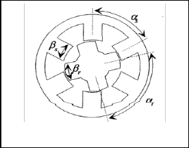
The machine topology studied is a double saliency three- phase SRM 6/4 with Ns = 6 stator teeth and Nr = 4 rotor teeth as represented "Fig. 1". Its operating principle, similar to the stepper motor, has long been known: by exciting successively![]()
Wu u I p
2
![]()
I p
i n
(3)
(4)
the three stator phases, the rotor teeth are positioned to max-
————————————————
The integration step i is the ratio of the peak value of current
Ip on the number of intervals n.
IJSER © 2012
International Journal of Scientific & Engineering Research Volume 3, Issue 3, March-2012 2
ISSN 2229-5518
Start
Data of studied machine Number of poles (Ns ; Nr) and phase (q) ? Pôles angles (s ; r) ? ….
Preliminary Design Process
Derivation of output equation: power/speed torque (T) Specific magnetic (Be) and electric (AL) loadings Dimensions of the envelope: Dr L=Dr/ ; Ds=Dr/kD Calculation of the other dimensions of stator & rotor
Fig. 1. Cross-section of studied SRM 6/4
Data of B-H curve & Analytic Fitting
Sub-programs (*.m)
Aligned (La.m) and unaligned (Lu.m) inductance
Energy and average torque (Torq.m); losses …
12
Aligned Position
10
8
Stop
Fig. 4. Flowchart of the simulation main program
6 Converted Energy
W = (Wa-Wu)

4
2
Unaligned Position
0
0 1000 2000 3000 4000 5000 6000 7000 8000 9000
Stator Excitation (At)
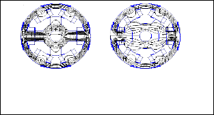
Fig. 2. Extremes magnetic characteristics flux vs. excitation mmf
(a) (b)
Fig. 3. Flux plot by FEM at fully (a) aligned and (b) unaligned positions
Genetic algorithms (GA) are stochastic optimization meth- ods defined by J. Holland [11]. They are based on the mathe- matical translation of natural phenomena that are natural se- lection (that determines which members of a population sur- vive and reproduce) and reproduction (which ensures mixing and recombination of parental genes to form down to poten- tial new ones). This translation is used for solving problems involving the modeling of all the steps that form the process of genetic algorithms and optimization of a function or system depends on several parameters which need to be calculated for well-defined criteria (maximization, minimization).
The steps for implementing a genetic algorithm can be summarized as following:
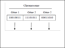
Coding: with the basic genetic algorithm, as founded by Holland, the first question to ask is: "how to describe a individual?". i.e, how the parameters can be coded? In an GA, we do not work directly with the data of the problem but with a representation of them called coding. The en- coded form of a solution of the objective function is a chromosome consisting of a set of genes and fully de- scribes an individual "Fig. 5 ". A gene that corresponds to a parameter and consisting of 0 and 1. In this case, each real value is encoded by its equivalent in binary. The set of in- dividuals is called population.
IJSER © 2012
International Journal of Scientific & Engineering Research Volume 3, Issue 3, March-2012 3
ISSN 2229-5518
Mutation: the mutation, which is a unary operation, represents the frequency with which genes of a given chromosome are muted. For example, a widely used muta- tion is to randomly draw a single gene in the chromosome and replace it with a random value with a probability of mutation Pm to expand the space of explored solutions "Fig.
7 ".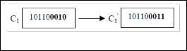
x1 x2 x3
Fig. 5. Illustration of the optimization coding varia- bles
Fig. 7. Mutation process
Initial population: the initialization is used to form the initial population. This step should not be overlooked be- cause if the population is not evenly distributed at the be- ginning, the evolution is likely to focus on a local optimum from which it can be difficult to escape. So we try to create an initial population as diverse as possible. Classically, for each individual in the population, the initialization mecha- nism is to randomly draw each bit in a string. for example, in the case of a binary representation, the draw is from the set {0, 1} [14].
Evaluation: individuals of the same generation will be compared and evaluated so to determine among them which ones are well suited to the given problem. This evaluation is based on a test of individuals according to a function called adaptation, evaluation or fitness function.
Selection: the selection operator is usually based on Darwin's theory [18]. So the best individuals are more like- ly to survive and reproduce. Individuals best suited are se- lected while the less well adapted are excluded without be- ing able to have offspring.
Crossover: The crossover operator is used to introduce a small change in the solution or change the direction of re-
Sometimes, important information stored in genes may disap- pear during the intersection operations. The essential role of the mutation is to remedy this type of degeneration [12]. On the other hand, the mutation operator's role is to prevent the algorithm to stagnate, if the population converges to a local optimum, the mutation operator operates with a high rate, that is to say a high probability Pm, which can disperse a sig- nificant portion of the population of the search space [18]. However, the choice of the value of Pm is critical as it introduc- es a significant impact on the performance of the genetic algo- rithm. In the specialized literature, it is suggested a very low probability of mutation to ensure the asymptotic convergence of the method in the exploration space [19].
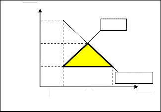
The design problem is formulated as a constrained, non- linear and multi-variable problem; for this reason, the pro- gram was written in a MATLAB environment. The design var- iables are the stator and the rotor pole arc angles. So the search region of these two parameters must satisfy certain condi- tions chosen according to the rules of feasible triangle “Fig. 8”. These rules are used to define the lower and higher limits of each variable so to define the search region, namely [20]:
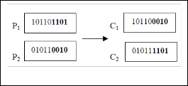
search (enrich the diversity of the population). Typically, the crossings are made by choosing two random individu- als (parents) to be "crossed" with a certain probability of crossover Pc means that when both parents are applying
for reproduction, we get a real x random according to a
s r
![]()
s 2 sm qNr
(5)
(6)
uniform [0,1], if x less than Pc, then we meet the parents in
order to generate two new individuals (children) "Fig. 6 ". The children replace their parents and form a new inter-
s
r r
![]()
2
(7)
mediate population.
2
![]()
sm
qN
30
s 45
![]()
N
(8)
r
r
rm 30 r 60 r sm
(9)
Fig. 6. Crossover operation
IJSER © 2012
International Journal of Scientific & Engineering Research Volume 3, Issue 3, March-2012 4
ISSN 2229-5518
s
sM=r-sm
s=r=r/2
D
s r
(1) B
s = r
sm=2/qNr
(2)
s < r
A C
(3)
(s + r)=r
r
0 rm=sm=30 rM=sM=60
Fig. 8. Feasible triangle
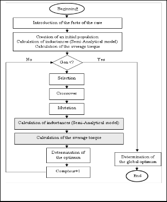
To find the optimal sizes of the pole arc angle of stator and rotor (Br and Bs), to have the maximum average torque, the model was coupled with our semi-analytical calculation tool GA. In this application, the rotor and stator pole arcs are the two parameters (genes) to optimize. For each pair (s, r) generated by the genetic algorithm, the first step is the deter- mination of the inductances and the second step is the calcula- tion of the average torque developed by the combination (s,
r).
The flowchart given in Figure 9 illustrates the design opti-
mization process.
The genetic algorithm parameters used for the design op-
timization problem are fixed by the following values:
- Population: 20 machines.
- Probability of crossover: 70%.
- Probability of mutation: 9%.
- Number of generations: 100.
The procedure described above was then realized and de- sired outcomes were identified by the genetic algorithm. The results are interpreted by the graphs "Fig. 10, 11, 12". The re- sults of the optimal design are presented in Table 1. The de- sign of the motor with a stator pole arc s = 40° and a rotor pole arc r = 50 ° shows an improvement of about 40% of the average torque compared with the initial construction. Figure
10 shows the change of the best average torque obtained in
each generation. The optimal solution is obtained at the 26th
generation.
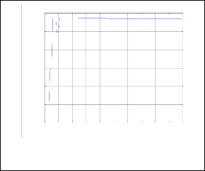
The results in Figures 11 and 12 show the variations of s and
r around their optimal values.
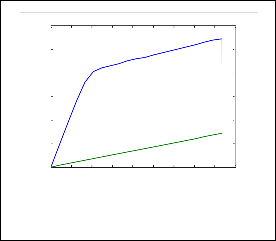
Figure 13 shows the magnetic flux according to the am-
pere-turns deduced from the analytical model for the initial
construction and optimized. Holding constant the magneto
motive force, a high electromagnetic energy is possible by op-
timizing the average torque.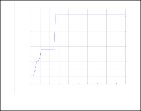
Fig. 9. Design optimization process
15.55
15.54
15.53
15.52
15.51
15.5
15.49
15.48
15.47
15.46
15.45
0 10 20 30 40 50 60 70 80 90 100
GENERATIONS
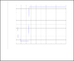
Fig. 10. Average torque over generations
40
39.9
39.8
39.7
39.6
39.5
39.4
39.3
39.2
39.1
39
0 10 20 30 40 50 60 70 80 90 100
GENERATIONS
Fig. 11. Change of s over generations
IJSER © 2012
International Journal of Scientific & Engineering Research Volume 3, Issue 3, March-2012 5
ISSN 2229-5518
49.94
49.92
49.9
49.88
49.86
49.84
49.82
0 10 20 30 40 50 60 70 80 90 100
GENERATIONS
[1] B. Multon et al., «Possibilités du MRVDS pour la motorisation de véhicules électriques», C-VELEC’95, Grenoble, 1-2 Fevrier 1995.
[2] T. L. Angle et al., «A New Unique HP Pump System», Proc. of the twenty-second int. pump users symposium, 2005.
[3] H. Kuβ et al., «Design of a high SRM for spindle drive", 5th Int. Conf.
– Workshop - CPE, 2007.
[4] M. Divandari, A. Dadpour, «Radial Force and Torque Ripple Optimi- zation for Acoustic Noise Reduction of SRM Drives via Fuzzy logic Control», Islamic Azad University Aliabad Katoul Branch, Iran.
[5] H. Torkaman, E. Afjei, «Hybrid method of obtaining degrees of Free- dom for radial airgap length in srm Under normal and faulty condi- tions based on magnetostatic model», Department of Electrical and Computer Engineering, Shahid Beheshti University, G.C. Tehran, Iran, Progress In Electromagnetics Research, PIER 100, 37-54, 2010.
[6] Jie Li, Hexu Sun, Zhaoming Lei, «Harmony optimization design of
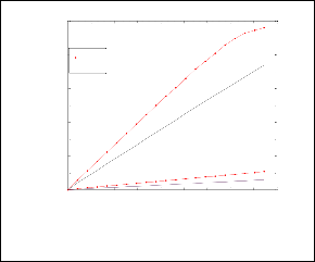
Fig. 12. Change of r over generations
10
9
8 Opt.Cons
Init.Cons
7 Wopt
6
5
4 Winit
3
2
1
0
0 200 400 600 800 1000 1200 1400 1600 1800
mmf [At]
Fig. 13. Extreme characteristics of flux vs. excitation current
TABLE 1
Results of Optimal Design

In this paper, an original method for optimizing a three- phase SRM 6/4 based on genetic algorithms was presented. The design optimization of stator and rotor pole arc teeth was carried out under MATLAB environment using a user-friendly program based on a semi-numerical approach developed for calculating the extreme values of inductance and correspond- ing energies. Preliminary results indicate a significant im- provement of average torque.
switched reluctance motor drive», School of Electrical Engineering
and Automation, Hebei University of Technology, Tianjin 300130,
China.
[7] M. Majchrowicz1, W. Jazdzynski1, «Selected Problems of Optimiza- tion of a Switched Reluctance Motor for an Electric Vehicle using Analytical Calculations», International Conference on Renewable En- ergies and Power Quality (ICREPQ’10) Granada (Spain), 23rd to 25th March, 2010.
[8] Funda Sahin, H. Bulent Ertan, Kemal Leblebicioglu, «Optimum ge- ometry for torque ripple minimization of switched reluctance mo- tors», Middle East Technical University, Electrical and Electronics Eng. Department 06531 Ankara Turkiye.
[9] Y. Alhassoun, « Etude et mise en oeuvre de machines à aimantation induite fonctionnant à haute vitesse », thèse de doctorat, ENSEEIHT, Toulouse, France, 27 Mai 2005.
[10] S. Taibi, « Contribution à l’étude, la conception, le dimensionnement et l’optimisation de machines à réluctance variable de type Vernier », Thèse de doctorat, Université des Sciences et Technologie de Lille, 12 juillet 2002.
[11] G. Berthiau et P. Siarry, «Etat de L’Art des Méthodes d’Optimisation
Globales», Sept.embre 2001.
[12] O. Hajji, « Contribution au développement de méthodes d’optimisation stochastique. Application a la conception des disposi- tifs électrotechniques », thèse de doctorat, Université des Sciences et Technologie de Lille, France, 03 décembre 2003.
[13] S. Brisset, « Démarches et Outils pour la Conception Optimale des Machines Electriques », thèse de doctorat, Université des Sciences et Technologie de Lille, France, 2007.
[14] M.Balaji, V.Kamaraj, «Design of High Torque Density and Low Torque Ripple Switched Reluctance Machine using Genetic Algo- rithm», European Journal of Scientific Research, ISSN 1450-216X Vol.47 No.2 (2010), pp.187-196.
[15] Mahadevan Balaji, Vijayarajan Kamaraj, «Particle Swarm Optimiza- tion Approach for Optimal Design of Switched Reluctance Machine», American Journal of Applied Sciences 8 (4): 374-381, 2011.
[16] X. D. Xue, K.W. E. Cheng, T.W. Ng, and N. C. Cheung, « Multi- Objective Optimization Design of In-Wheel Switched Reluctance Mo- tors in Electric Vehicles », IEEE-TIE, Vol. 57, NO. 9, Sept. 2010.
[17] R. Krishnan, Switched Reluctance Motor Drives—Modeling, Simula- tion, Analysis, Design, and Applications. CRC Press, 2001.
[18] B. Sid, « Optimisation topologique de structures par algorithmes génétiques », Thèse de doctorat, Université de Technologie de Bel- fort-Montbéliard, 05 décembre 2006.
[19] L. Mokrani, «Contribution à la CAO Optimisée des Machines Elec- triques, Application au Moteur Linéaire à Induction», Thèse de Doc- torat d'Etat, Université de Batna, 2005.
[20] P.J. Lawrenson et al., « Variable-speed SRM’s », IEE Proc., Vol. 127, Pt.
B, No. 4, July 1980, pp. 253-265.
IJSER © 2012