Inte rnatio nal Jo urnal o f Sc ie ntific & Eng inee ring Re se arc h Vo lume 3, Issue 2, Fe bruary -2012 1
ISSN 2229-5518
“Techniques to ensure minimum distortion of an assembly of metal parts induced due to the process of welding used for an assembly”
K. D. Hardik ar, D. J.Ni dgalkar, Dr. K.H. Inamdar
—————————— ——————————
Welding process is widely used now-a-days for metal joining operations. The most common and widely used metal joining process is welding process. The dimensional quality of assembly is ensured by two ways either by optimizing manufacturing of parts to be assembled qualitatively within dimensional tolerance limit or by optimizing the process of joining which joins the parts to be assembled. It is observed that the joining process like welding contributes towards the distortion induced to a larger extent. So it is very essential to optimize the process of welding. Welding process optimization leads towards dimensional accuracy of assemblies and overall accuracy of machine or mechanism. Various techniques are used to reduce the distortion induced in assemblies due to the welding process. The measure ca use of distortion induced is welding sequence used for assembly. Different techniques to reduce the welding distortions are disused subsequently.
There are various techniques and methodologies to reduce the distortion induced in assembly of metal parts due to the
———— ——— ——— ——— ———
D.J.Nidgalkar, Lead Consultant-CAE, Mahindra Engineering Services,
Pune, India,E-mail: nidgalkar.deepak@mahindraengg.com
Dr. K.H. Inamdar3, Asst. Prof. Department of Mechanical Engineering,
Walchand College of Engineering, Sangli,India, E-mail: ikedar@yahoo.com
welding process used for an assembly and are as follows:
VFT is a state-of-the-art fabrication simulation technology that allows rapid solutions for large, complex metall ic structures containing both single-pass and multi-pass welds and allows the user to consider or input all critical variables. It can be used in product design stages to help the weld design and in the manufacture stage to determine the optimal weld processes to minimize welding-induced distortion. For weld process models, various software tools are used for optimization and for fabrication metal process design. Me- thods used to control weld induced distortions is to decide proper welding sequence for minimum thermal distortions induced. Virtual fabrication technology is one of the methods to reduce thermal distortions by predicting the sequence of assembly welding virtually before fabrication.
Consider case of a submarine hull manufacturing from steel
sheet by VFT. 2.5m diameter and 2.3m long cylinder welded to a 101.4mm thick ring. Three weld sequences are considered for welding as first sequence is to tack the cylinder, perform the multi-pass seam weld, and then weld the cylinder to the end ring with the outside fillet, and inside fillet. The second sequence is to tack the cylinder, then tack the cylinder to the end ring from outside and inside Tee fillet locations, perform seam weld, and weld outside the Tee fillet and inside the Tee fillet. The third sequence has the same tacking procedures as the sequence two. But at first the inside Tee fillet was welded, then outside Tee fillet, and finally the seam weld. It was found that the radial distortion is reduced and can meet th e design
IJSER © 2012
Inte rnatio nal Jo urnal o f Sc ie ntific & Eng inee ring Re se arc h Vo lume 3, Issue 2, Fe bruary -2012 2
ISSN 2229-5518
requirement. The reason that the third sequence produces less distortion is that after the Tee fillet weld the cylinder is stiffer so that the seam weld induced distortion is smaller. Sequencing is clearly the preferred procedure for this case [1].
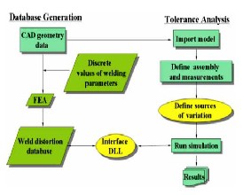
A general and efficient methodology has been developed to analyze dimensional variations of a welded assembly, taking into account of weld distortion due to heat induced from sequence welding operation. Weld distortion is generally probabilistic because of the random nature of welding parameters such as the welding speed, maximum welding temperature corresponding to the welding sequence, ambient temperature, etc. Tolerance analysis methodology comprises of establishment of a weld distortion database and tolerance analysis using the database. The methodology is as shown in the Fig.1 below.
Fig.1 Database Generation and Tolerance Analysis [5]
To establish the database, thermoelastoplastic finite element
analyses are conducted to compute the weld distortion for all combinations of discrete values of major welding parameters. In the second step of tolerance analysis, the weld distortion retrieved from the database is taken into account in addition to the dimensional tolerances of the parts. As a result of such an analysis, sensitivities of the assembly’s dimensional variations to the part tolerances and weld distortion are obtained, which could provide a guideline for improving dimensional quality of assembly. By using this technique the parameters which provides minimum distortion as well as minimum tolerance variation is used for quality fabrication [5].
Pre-straining technique used to control welding induced distortion for a fixed sequence of welding in heavy industries. With pre-straining, some plates are pre-bent, plastically, before welding. This is in contrast to pre-cambering, where the bending during the weld process is elastic. This may have applications in many large ship fabrication areas where thick plate must be welded and distortions controlled, such as bulkheads. Before assembling welded structure, plates are bent into permanent shape based on predictions using
software. After welding, welding-induced distortion makes the bent shape become straight. To determine the pre-bent shape and magnitudes, a large amount of experiments needed to be conducted (in the past) before weld modeling software was available.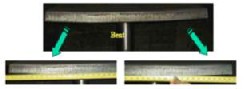
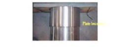
(a) Bef ore w elding
(b) Af ter Welding and Machining
Fig.2 (a, b) Pre-Straining of Plate [1]
In the Fig.2 pre-straining technique is described to mitigate
distortion resulting from the J-groove circumferential fillet
weld between a very long cylinder and a plate. Before welding, the plate was bent as shown in the Fig.2 (a). End edge of the plate was pre-bent to about 7 mm away from middle straight part of the plate in the cylinder axle direction, as marked in Fig.2. It is import to note that the pre-bent plate has 3 nearly straight sections with two bend radii. After welding, the pre-bent plate becomes almost flat as shown in Fig 2 (b). It should be pointed out that the plate was only bent in one dimension. Rectangular and the J-groove circumferential fillet weld are close to the two edges of the short side of the rectangular. If the plate is square and the centre of circumferential weld is around the centre of the plate, it is necessary to bend the plate in two dimensions. This pre-straining technique is easy to use and very effective. The use of this technique makes the design procedure practically economical for any type of large structure fabrication [1].
The objective of the method is to achieve optimum setting of welding process parameters for the minimum distortion induced by using a Taguchi method. Taguchi philosophy technique for quality engineering provides 2 tents: - first is reduction in variations (improved quality) of a product or process and second is proper development strategy can intentionally reduce variations. The Taguchi method provides a lot of conveyance in the optimization of spot welding process variables. There are a number of variables associated with this process and are 5 to 7 in number. Value of every variable puts an adverse effect on the output of the welding process that is weld strength and distortion induced. So, there is a need to investigate the effect of change of values of each and every parameter involved in the process on the output. Since the output required should be as per the desire of the
IJSER © 2012
Inte rnatio nal Jo urnal o f Sc ie ntific & Eng inee ring Re se arc h Vo lume 3, Issue 2, Fe bruary -2012 3
ISSN 2229-5518
application, result of the values of different process variables on the output is required to be investigated. The effect of process variables can be studied only by performing the experiments on different material sheets of different thicknesses. Now, performing the experiments on a hit and trail basis is a tough task and very expensive also. So, a proper model of experimentation is required to be formulated. Ta- guchi techniques help a lot in the formulation of an effective experimental model for these types of problems. Use of this technique not only reduces the number of experiments but also gives a proper optimization of the values of process variables to get an effective weld strength and distortion induced. The welding process parameters used for Taguchi approach are weld cycle time, cooling time between sequence welding, current required for the resistance spot welding, pressure, electrode diameter, welding sequence, HAZ, etc. by using values of welding parameters, s equences for different levels and by using Taguchi design matrix array the optimum parameters are worked out for the output as minimum thermal distortion for improvement of dimensional accuracy while manufa cturing [4].
Joint rigidity method is used for effectively determining the welding sequence. For welding sequence the deviation from the actual geometry is measured by using CMM machine and compared with the software simulation results. As shown in Fig. 3 Joint rigidity can be defined as the resistance to angular bending of a T-joint under a unit moment applied to the joint.
Joint Rigidity = m/,
m : Unit applied moment,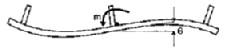
: Angle of rotation per unit applied moment
sequence found by joint rigidity method can improve the flatness of the panel and ensures minimum distortion in the assembly [6].
In this method the combination of clampin g and welding sequentially according to clamping is used to reduce the distortion induced in sheet metal assemblies. Consider a following example of model of Sheet Metal Assembly.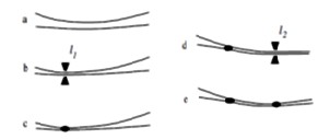
Fig.5 Model of Sheet Metal Assembly [7]
In Fig.5, (a) two sheets of slightly different shape are to be
joined. A clamp is applied at location l1 in (b), and the two pieces are welded there. In (c) the clamp has been released. Another clamp is applied at location l2, and another weld is made at that location as shown in (d).The final joined product is displayed in (e). Two sequences are considered for welding of two sheets 1) Clamping at one location and welding sheets from that location 2) Clamping at another location and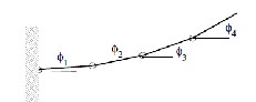
welding of sheets from that location. The results obtained are very different affecting the shape of final assembly showing the importance of sequence welding. A cantilever beam configuration of a metal sheet is as shown in Fig.6
Fig.3 Joint Rig idity [6]
For example, consider a panel consisting of T-joints as shown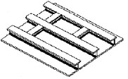
in the Fig. 4 below.
Fig.4 Panel consisting of T-joints [6]
Four welding sequences are used for analysis by a joint
rigidity method. Joint rigidity method says a unit moment applied to the middle joint of a panel results in smaller angular rotation of the skin plate at the joint than applying the same unit moment to the joints at the free edge of the panel. As a conclusion T joint rigidity method says that welding sequence that starts with more rigid joints and moves progressively towards less rigid joints would result in less distortion. It is also concluded that the optimum weld
.
Fig. 6 Cant ilever Beam Conf iguration [7]
The configuration is simulated for welding sequences as 1)
Welding Inside-Out 2) Welding Outside-In. Results were analyzed and it is concluded that to achieve tolerance limits and smallest deviation it would be best to perform clamping as well as welding from Inside-Out [7].
In this technique spot welds are modeled either by using coincident nodes (joining the corresponding nodes of components of an assembly) or by using a rigid connection in between. Welded system should behave like a discrete welded system rather than a continuous system so that there is at least one free node. In modeling the mesh size does matter to a greater extent. For capturing highly localized stress and distortions the welding sequence for welding as well as mesh refinement are critical parameters. In weld modeling, how to include spot welding sequence in variation simulations and correlation between offset and standard deviation for different welding sequences is investigated as well as no. of weld points
IJSER © 2012
Inte rnatio nal Jo urnal o f Sc ie ntific & Eng inee ring Re se arc h Vo lume 3, Issue 2, Fe bruary -2012 4
ISSN 2229-5518
needed to lock the geometry are also to be considered. In most of the cases it is observed that distortion is only due to influence of heat and can be controlled by sequencing method. In FEM weld modeling method, Simulation is based on data of measurements before welding and simulation results are compared with measurements after assembly welding for different welding sequences. Consider an example of simple T-joint as shown in Fig. 7. The modeling before welding is shown in Fig.7 (a).welding is carried out at the intersection of two plates from both sides by using various sequences of welding. By using FEM modeling and simulation technique distortion due to heat induced in welding process is calculated and is as shown below in Fig.7 (b).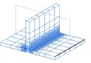
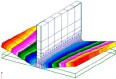
(a) Bef ore w elding
(b) Af ter w elding
Fig. 7 FEM Modeling [3]
Deviation in values measured before welding and after welding gives the distortion in assembly for the corresponding sequence of welding. The sequence that provides minimum thermal distortion becomes the solution towards the quality fabrication within distortion tolerance limit [3].
Consider another example of diode packaging. The assembly
is as shown below in Fig. 8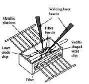
Fig.8 Diode Packaging [2]
Controlling welding-induced-alignment-distortion (WIAD)
and maintaining coupling efficiency is obviously the most challenging issue in a ssembling of fibre-optic components. Previous investigation has revealed that the WIAD in butterfly laser diode module packaging could be mitigated by properly choosing weld process parameters such as welding sequence Diode Assembly is done by spot welding at locations shown in Fig.9.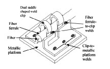
Fig.9 Diode Weld Assembly [2]
For diode packaging three cases for welding sequence are investigated as 1) Simultaneously welding front and rear welds followed by cooling 2) Front weld followed by cooling and the rear weld 3) Rear weld followed by short time cooling and then front weld. The effect of welding sequence on WIAD is studied numerically by finite-element method (FEM) with a more realistic physics based laser welding model and experimentally by welding prototype butterfly packages. Results from both methods are compared. It is shown that the influence of welding process parameters on WIAD is significant and WIAD control is possible if proper welding sequence is employed. . The results then obtained in this case shows that for minimum WIAD the only sequence for welding is 3rd one i.e. welding the rear side first then short cooling and then welding front side [2].
By selecting the proper welding methodology and welding
sequence the distortion of assembly is reduced drastically.
Use of a proper technique leads to accuracy enhancements and eliminates the need for expensive distortion corrections. Software simulation techniques or a VFT reduces the process costs, improves quality and permits pre-machining concepts to be used for accurate dimensional assembly and fabrication.
[1] F.W. Brust, Paul Scott, ―Weld distortion control methods and applications of
weld modeling,‖ Transactions, SMiRT, Toranto, August 2007, paper #B05/1.
[2] Lin, Echele, Shi, ―Effect of welding sequence on welding induced alignment
distortion in butterfly laserdiode module,‖ University of California, eScholarship, 02-
01-2005.
[3] Scott E. Zilincik and Wm. Jeffrey DeFrank, Ernie Monroe and Salman Khan, ―A new approach to evaluating spot welds for automotive durability,‖ Society of Auto- motive Engineers, Inc., 982277.
[4] Dr.R.M.Warkhedkar, M.S.Mukhedkar, ―Optimization of spot welding using taguchi method,‖ International Conference on Sunrise Technologies, 13th – 15th Jan
2011.
[5] Dongyul Lee, Ki Eak Kwon, Jaeyeol Lee, Haeseong Jee, Seong Wook Cho, Jong-
Gye Shin, Gyubong Lee, ―Tolerance analysis considering weld distortionby use of
pre-generated database,‖ Journal of Manufacturing Sciences and Engineering, August
2009, Volume131/ 041012-1.
[6] C.L.Tsai, S.C. Park, W.T.Cheng, ―Welding distortion of a thin plate panel struc-
ture,‖ Welding Research Supplement, 156-s/May1999.
[7] Kathleen Hoffman, Fadil Santosa, ―A simple model of sheet metal assembly,‖
Society for Industrial and Applied Mechanics, 2003, Vol.45, No.3, pp. 558-573.
IJSER © 2012