International Journal of Scientific & Engineering Research, Volume 2, Issue 11, November-2011 1
ISSN 2229-5518
Technique for EXAMING Epicyclic Gear Box
Krish Gupta, Ajay Sharma
Abstract- This paper presents a method for analyzing epicyclic gearboxes by evaluating the speeds, torques and efficiency of the external elements in epicyclic gear mechanisms, as well as the total ratios of the gear box. The method is based on the equations that describe each epicyclic gear mechanism and rules that assign appropriate codes to the external elements. The method emphasizes how power flows are transmitted through the epicyclic gears. Analysis of an epicyclic gear box is performed to illustrate the proposed method.
Keywords - epicyclic gear, epicyclic gearbox, power flows, efficiency
—————————— ——————————
The fundamental objectives of this study are:
1) Calculate and experimentally observe the angular velocity ratios of gear trains,
2) Experimentally obtain the torque ratios of gear trains,
3) Compute the efficiencies of gear trains.
Gear trains of the type shown in Figures 1, 3, 4 and 5 are called epicyclic gear trains or planetary gear trains. In these gear trains, one or more gears are carried on a rotating planet carrier rather than on a shaft that rotates on a fixed axis. Several types of gear trains may be shifted manually to obtain greater or lesser values of speed reduction. The shifting process, however, is difficult to accomplish automatically with gears that rotate about fixed centers. On the other hand, epicyclic gear trains are readily adapted to automatic control. Some epicyclic gear trains are designed to change velocity ratios simply by using electrically or hydraulically operated band brakes to keep one or more of the gears stationary. Other epicyclic gear trains operating with fixed velocity ratios are selected for their compact design and high efficiency.
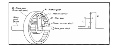
A simple epicyclic gear train consists of a sun gear (S) in
Figure 1. An epicyclic gear train and its associated terminology
The general expressions pertaining to the gear train are given below:
For a gear train (Fig. 2), if Ti = input torque, θi = input angular displacement, TO = output torque, θo = output angular displacement, then
![]()
Angular velocity ratio R i v
o
Input work = Ti * θi
Output work = To * θo, and
Outputvork To o
the center, a planet gear (P), a planet carrier or arm (C), and an internal or ring gear (R). The sun gear, ring gear and planet carrier all rotate about the same axis. The![]()
Efficiency (h) =![]()
InputWork
Tii
planet gear is mounted on a shaft that turns in the bearing in the planet carrier and meshes with both the sun gear and the ring gear. (Figure 1)
If the input shaft tends to rotate in the direction of Ti, the gear train is balanced if
Ti θi = Mfriction + To θo
IJSER © 2011
International Journal of Scientific & Engineering Research, Volume 2, Issue 11, No
ISSN 2229-5518
If there is no friction loss, the efficiency should be 1.0 and the output work equals to input work. The corresponding To is ideal and is equal to Ti R
v
To =Ti / R
v
Where To is the ideal output torque. With the existence of Mfriction, The actual output torque is smaller. The smallest To to balance the gear train will be used to determine the system's efficiency. The efficiency can only be determined experimentally.
Calculation of velocity ratio can be performed by either the formula method or the tabular method. This ratio can also be experimentally obtained.
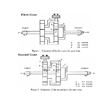
In this experiment the gear ratio is initially calculated using the formula involving the number of teeth. The angular velocity ratios and the torque ratios of the two gear units are calculated experimentally. The procedure is described below:
st
1. To calculate the angular velocity of the 1
nd
gear unit,
lock the 2
gear unit using the lock pin.
2. Rotate the input shaft one full turn clockwise (as viewed from the input shaft end) and observe the sense and magnitude of rotation of the output shaft (as viewed from in input shaft end). Repeat the
nd
procedure for the 2
i
st
gear unit with the 1
unit locked.![]()
From this
o
is calculated where θ is the rotation of
i
input shaft (360°) and θ
o
output shaft.
is the rotation read at the
3. To estimate the torque ratios lock one of the gear units and hang a weight of 200gm at the input shaft.
4. Start adding weights at the output shaft till equilibrium is achieved. Repeat the procedure for the other gear unit.
IJSER © 2011
International Journal of Scientific & Engineering Research, Volume 2, Issue 11, November-2011 3
ISSN 2229-5518
5. Record the weight at the output shaft for calculation purposes.
train. Performing a static analysis, the torques were found to be controlled by
T6= (N2+N3) {T2/N2+T5/N5} T5= - RT2
Where the T’s represent torques on each element in the train, and the N’s represent number of teeth in each gear in the train. Using these equations, it became apparent that the goal of achieving power balance at equal and opposite input speeds was impossible. If ω and ω are assumed to be equal and
2 5
opposite, then to achieve a power balance, T and T must also
2 5
Obtain the following results for this experiment.
1. Theoretical gear ratio (show calculations, using the number of teeth, for both gear trains).
i
be equal and opposite. According to equation 3, this means R must be 1. Unfortunately, this takes the denominator of equation 1 to zero, which drives ω to infinity. What had
6
seemed intuitively a simple problem to solve had led to a singularity in the solution space.
2. Angular velocity ratio![]()
Rv
o
which is equal to
To verify the theoretical relations used in gear efficiency
the experimental angular rotation ratio.
3. Torque ratio defined by To / Ti.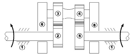
4. Efficiency.
Figure 3: Gear train to be used in the Human Powered Vehicle
Team’s design effort
Using Willis’s *1+ method for finding the kinematic solution of
the gear train, it was found that the mechanism was governed
by
ω6= R ω5 – ω2 /R -1
where the ω’s represent rotational speeds of each element in
the gear train, and R is the basic transmission ratio of the gear
determination
Experimental bench:
Experiments are performed to determine the static efficiency a
two-carrier, two-speed planetary gear train manufactured by scheme 55V5 depicts the structural scheme and the determined shaft torques with no regard to losses. The gear train is reversible with two speed ratios.
Ibr=5 and Ibr= -264267
With the help of original additional elements any of the coupling gear trains could be blocked so that only the other one is operational.
A bench is developed and it allows static and dynamic studies on the gear train.
Theoretical basis of the experiment
The kinematic speed ratio of the gear train when working with one degree of freedom (one brake is active) is
Ik=WA/WB,
Where wA and wB are the respective angular speeds of the input and the output torques.
The power of the input and output torques is respectively. PA= TA. wA and PB = TB. wB
.
The efficiency is
η= PA/PB =TB. ω B /TA. ω A <1
If the losses are disregarded (η = 1)
TB= TA .ik
IJSER © 2011
International Journal of Scientific & Engineering Research, Volume 2, Issue 11, November-2011 4
ISSN 2229-5518
and if the losses are taken into account
TB=TA.ir
Where ik and ir are the kinematic speed ratio and the ratio of the torques (input and output).
The above results are to be obtained for both the gear units (#1 and #2).
Torque Distribution in Epicyclic Gear Units: The most significant advantage of Epicyclic Gears is that the input torque is distributed to all of the planets. Epicyclic Gear Units are particularly effective at balancing the torque equally between the planets. Depending on the gear ratio 3, 4, 5 or 6 planet wheels may be installed. Each gear mesh then transmit, only 1/3, 1/4, 1/5, 1/6 of the respective torque. The radial forces of each Gear mesh offset each other. So Epicyclic Gear Units a compact design is achieved combine the with low strain on the componenet.
Mechanisms and Dynamics of Machinery, Fourth Edition, H.H. Mabie, C.F. Reinboltz, Wiley & Sons, Inc.
Design of Machinery, Robert L. Norton, McGraw Hill, Third Edition, 2004.
Oprean, I. M. Automatic transmissions for car, 1999, pp.
20–91 (Printech Publishing House, Bucharest, RO).
Pennestri, E. and Freudenstein, F. The mechanical efficiency of epicyclic gear trains. J. Mech. Des., 1993, 115(3), 645–651.![]()
IJSER © 2011