International Journal of Scientific & Engineering Research, Volume 4, Issue 6, June-2013 3034
ISSN 2229-5518
TONE MAPPING OF HDR IMAGE FOR LDR DISPLAY USING GUIDED IMAGE FILTER
Shambulinga M, T.C.Thanuja, N Ramanathan
Abstract— This paper proposes a novel scheme of presenting high dynamic range images on low dynamic range displays using gamma correction based tone mapping and guided image filtering. The typical high dynamic range image is split into base layer and detail layer using guided image filter. Dynamic range of the base layer is compressed or expanded using gamma correction method. The gamma correction with different gamma coefficients are applied to the image to generate gamma compressed and gamma expanded images. Then both the images are combined according to the weight functions based on local variances. The local variances are used as local weights to bring out the detail information. Guided image filter computes the filtering output by considering the content of the guidance image, which can be input image itself or any other image. The guided filter is used as edge preserving smoothing operator. Finally detail layer of the guided image filter is added to the output image obtained from gamma correction method. The overall output image presented on LDR display is nearly the same as the original HDR input image in terms of visual quality.
Index Terms— Guided image filter, gamma correction, high dynamic range image.
—————————— ——————————
useful in many applications, most of the current display
1 INTRODUCTION
High dynamic range imaging is a set of methods used in imaging and photography to allow a greater dynamic range between the lightest and the darkest areas of an image as opposed to the current standard digital imaging methods or photographic methods. HDR image can represent more accurately the range of intensity levels found in real scenes, from direct sunlight to faint star light, and is often captured by way of a plurality of different pictures of the same subject matter. Non HDR camera captures a picture at one exposure level with limited contrast range. This results in the loss of detail in dark and bright areas of the picture. HDR compensates for this loss of detail by taking multiple pictures at different exposure levels and intelligently stitching them together to produce a picture that is representative in both dark and bright areas.
Recently, high dynamic range images have been widely used for various purposes such as medical tomography, industrial monitoring system, surveillance system, computer vision system, scientific research application, broadcasting system, consumer application etc. Although HDR images are
————————————————
• Shambulinga M, in 4th Semester M Tech in Digital Communication Engineering, Telecommunication engineering Dept , R. V. College of Engineering, Bangalore, India. E-mail: mshambu89@gmail.com
• Dr T. C. Thanuja, Telecommunication engineering Dept, R. V. College of
Engineering, Bangalore, India. E-mail: thanujatc@rvce.edu.in
• Mr Ramanathan N, Technical Director, Davinci Nanotech Pvt. Ltd., Bangalore, India. E-mail: ramanathan@davincinanotech.com
devices cannot fully display the detailed information of HDR images, since the dynamic ranges of them are much smaller than those of the images obtained in the HDR environment. Therefore, a dynamic range mapping technique is necessary to display HDR images on LDR display devices.
In order to show the information of HDR images as much as possible under the LDR environment while maintaining the images visually pleasing to the user, a new dynamic range mapping method using gamma correction is proposed. First guided image filter is used to bifurcate the image into base layer i.e., lower frequency components of the image and detail layer i.e., higher frequency components of the image. Then gamma correction with different gamma coefficients is applied to the base layer of the guided image filter to generate the gamma compressed and gamma expanded images. The proposed method adequately combines them according to the weight functions based on the local variances. The local variances are used to bring out the detailed information. The local variance becomes larger as the details in local area become visible. Therefore, the local area which has the largest local variance should have dominant influence on the result image among the candidate images. As a result, the local variances are used as local weights to appropriately map the dynamic range.
This paper is organized as follows. Overview of guided image filter, tone mapping techniques, experimental results, and conclusion.
IJSER © 2013 http://www.ijser.org
International Journal of Scientific & Engineering Research, Volume 4, Issue 6, June-2013 3035
ISSN 2229-5518
2 OVERVIEW OF GUIDED IMAGE FILTER
The guided filter [2] generates the filtering output by considering the content of a guidance image which can be input image itself. The guided image filter performs as an edge preserving smoothing operation like the popular bilateral filter [1], but has better performance near the edges. The guided filter has a fast and non-approximate linear-time algorithm, whose computational complexity is independent of the filtering kernel size. Experiments show that the guided image filter performs well in terms of both quality and efficiency in a great variety of applications, such as noise reduction, detail smoothing/ enhancement, HDR compression, image matting/ feathering, haze removal, and joint up sampling.
where r and s are the input and output values, respectively. These values are non-negative real values. In the 8-bit digital image, the range of values is from 0 to 255. The case γ> 1 is often called gamma compression, and γ < 1 is called gamma expansion.
The gamma compression effectively brings out the detailed information in dark region. However, the details in bright region are saturated toward white. On the contrary, the gamma expansion effectively brings out the detailed information in bright region. However, the details in dark region are diminished. Therefore, if the results of gamma compression and gamma expansion are adequately combined according to the characteristics of the regions, the details in both dark and bright regions are brought out at the same time, resulting in the compression of the dynamic range. That is, the
Input
Image
ϵ
b
Find mean,
variance,
covariance within window a
Guidance Image
Base layer
+
x
concept of this method is to generate several gamma corrected
images as candidate images for final compression result, and combine them according to weight functions.
3.2 Choice of gamma coefficients
The gamma coefficients determine the degree of dynamic range compression. However, if extremely strong compression is performed, it causes the degradation of visual contrast. Therefore, desirable gamma coefficients should be chosen to generate several candidate images according to the characteristics of the input images. This method uses two
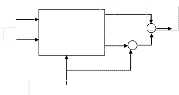
Figure 1: Block diagram of guided image filter
Figure 1 represents the block diagram of the guided image filter, a and b are the filter coefficients computed using input image and guidance image [2].
candidate images, one is gamma compressed image for
compressing dark region, and the other is gamma expanded image for compressing bright region. The input image is divided into dark and bright regions to decide gamma coefficients. Then, the mean of each region is calculated as
𝑟(𝑖, 𝑗)
3 HDR TONE MAPPING
Tone mapping reduces the dynamic range, or contrast ratio, of the entire image, while retaining localized contrast (between neighbouring pixels), tapping into the research on how the
𝜇𝑑 = �

𝜇𝑏 = �
𝑁𝑑
𝑟(𝑖, 𝑗)
𝑁𝑏

𝑖𝑓 (𝑟 < 𝑟𝑚 ) (2)
𝑖𝑓 (𝑟 > 𝑟𝑚 ) (3)
human eye and visual cortex perceive a scene, trying to
represent the whole dynamic range while retaining realistic colour and contrast.
The guided image filter output contains the lower frequency components of the image called base layer. The difference between the input image and base layer is the detail layer. Now dynamic range of the base layer is compressed using gamma correction method.
where r is the input image, (i, j) is the location of pixels in r.
rm is the middle point which is the criteria for dividing the
regions. µd and µb are the means of dark and bright regions. Nd
and Nb are the number of pixels included in each region, respectively.
This method selects the gamma coefficients as the functions of differences between the mean of each region and rm. These functions are modeled as
(𝑟𝑚 − 𝜇𝑑 ) ∗ 𝜋
3.1 Gamma correction
Gamma correction is a non liner operation used to compress

𝛾𝑐 = 𝛼𝑠𝑖𝑛 �
2 ∗ 𝑟𝑚
� + 1 (4)
and expand the luminance values in imaging system. Gamma
1 (𝜇𝑏 − 𝑟𝑚 ) ∗ 𝜋


= 𝛼𝑠𝑖𝑛 � � + 1 (5)
correction is defined by the following power-law expression
𝛾𝑒
2(255 − 𝑟𝑚 )
𝑠 = (

𝑟
255
1
)𝛾 ∗ 255 (1)


where 𝛾𝑐 and 𝛾𝑒 are the gamma coefficients for gamma compression and expansion, respectively, and 𝛼 is a weight.
IJSER © 2013 http://www.ijser.org
International Journal of Scientific & Engineering Research, Volume 4, Issue 6, June-2013 3036
ISSN 2229-5518
𝛼 controls the strength of the gamma curves. Therefore, 𝛼
should be suitably chosen by considering the dynamic range
𝜎𝑐 ∗ 𝐺𝑐 + 𝜎𝑒 ∗ 𝐺𝑒

𝑜𝑢𝑡𝑝𝑢𝑡 =
𝜎𝑐 + 𝜎𝑒
(10)
of the image. For the image requiring a stronger compression,
𝛼 should be high, while for the image, needing a weaker compression, 𝛼 should diminish towards 0, meaning
practically no compression.
3.3 Local weights for dynamic range compression


When both 𝜎𝑐 and 𝜎𝑒 are zero at the same time, 𝜎𝑐 and 𝜎𝑒 are
altered to different values to avoid dividing by zero as


𝜎𝑐 = 𝐵𝜎𝑐 𝑎𝑛𝑑 𝜎𝑒 = 𝐵𝜎𝑒 , 𝑖𝑓(𝜎𝑐 = 0 𝑎𝑛𝑑 𝜎𝑒 = 0)(11)
where 𝐵𝜎𝑐 and 𝐵𝜎𝑒 are the latest non-zero values among the
previous 𝜎𝑐 and 𝜎𝑒 , respectively. 𝐵𝜎𝑐 and 𝐵𝜎𝑒 are defined as
For each pixel position, the local variances are used as local
𝐵𝜎
= 𝜎 , 𝑖𝑓(𝜎
≠ 0) (12)
weights to bring out the detailed information. As shown,
gamma compression brings out the detailed information in dark region, while gamma expansion diminishes them in that region. That is, the result of gamma compression shows better performance than that of gamma expansion in dark region for the purpose of dynamic range compression. On the contrary, gamma expansion brings out the detailed information in bright region, while gamma compression diminishes them in that region. Bringing out the detailed information in local area means the increase of local variances. Therefore, the local variance becomes larger as the details in local area become visible. As a result, if local variances as local weights are used, the result of gamma compression dominantly influences the output image in dark region, and that of gamma expansion dominantly influences the output image in bright region. It means that, this method can compress both dark and bright regions at the same time by adequately combining candidate images.
To generate candidate images, gamma corrections with different gamma coefficients, which are chosen by equation (4) and (5), are applied to the observed image. From these images, the local variances are defined as


𝑐 𝑐 𝑐


𝐵𝜎𝑒 = 𝜎𝑒 , 𝑖𝑓(𝜎𝑒 ≠ 0) (13)
where 𝜎𝑐 and 𝜎𝑒 are the previous local variances.
Equation (10) represents the dynamic range
compression of the base layer. And finally the detail layer is
added to this gamma corrected output to obtain the overall output image to be presented on the LDR display.
4 EXPERIMENTAL RESULTS
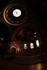
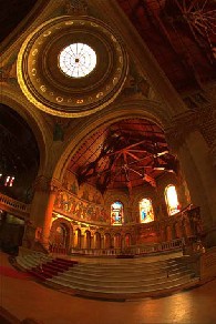
In order to demonstrate the performance of the proposed method, guided image filter algorithm and gamma correction algorithm are implemented in MATLAB and the simulation results are given in figure 2, 3, 4 and 5. HDR image considered in figure 2 is of size (768 x 512) and figure 4 is of size (3000 x
1500). Parameters considered in simulation of both figure 2
and 4 are α=1, local window size is 3x3, ε=0.01. Figure 2 and 4
are the original HDR image displayed on LDR display. Figure
3 and 5 are the dynamic range compressed output image.
1 2

𝜎𝑐 = 𝑁 ∗ � (𝐺𝑐 (𝑖, 𝑗) − 𝜇𝑐 )
(𝑖 ,𝑗)∈𝐻
(6)
1 2

𝜎𝑒 = 𝑁 ∗ � (𝐺𝑒 (𝑖, 𝑗) − 𝜇𝑒 )
(𝑖 ,𝑗)∈𝐻
(7)
Where Gc is the image, which gamma compression with γc
is applied. Ge is the image, which gamma expansion with γe is

applied. 𝜎𝑐 and 𝜎𝑒 are the local variances of Gc and Ge,
respectively. H is a local window, and N is the number of
pixels in H. (i,j) is the location of pixels in H. 𝜇𝑐 and 𝜇𝑒 are the
local means of Gc and Ge. which are defined as
1

𝜇𝑐 = 𝑁 � 𝐺𝑐 (𝑖, 𝑗)
(𝑖 ,𝑗)∈𝐻
(8)

1
𝜇𝑒 = 𝑁 � 𝐺𝑒 (𝑖, 𝑗)
(𝑖 ,𝑗)∈𝐻
(9)
Finally, the output image where local weights are used is produced by combining Gc and Ge. It is expressed in equation as
Figure 2: HDR image
IJSER © 2013 http://www.ijser.org
International Journal of Scientific & Engineering Research, Volume 4, Issue 6, June-2013 3037
ISSN 2229-5518
edge preserving smoothing filter. Gamma correction used in this method is simple and computationally efficient. Simulation results show that the proposed method produces good results in terms of visual quality. Future work includes compilation of experimental results pertaining to a variety of input HDR images and analysis and comparison of results obtained from various tone mapping algorithms.
6 ACKNOWLEDGMENTS
I deeply express my sincere gratitude to my guide Dr.K.Sreelakshmi, Associate professor, Department of telecommunication, RVCE, bengaluru for her guidance, continuous encouragement and assistance for this project.
I also extend my cordial thanks to Davinci Nanotech Pvt Ltd, bengaluru, for providing me an opportunity to carry out the internship in its organization..
Figure 3: compressed output image
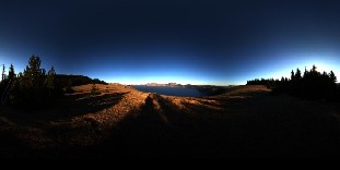
Figure 4: HDR Image
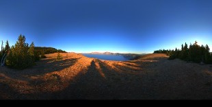
Figure 5: compressed output image
5 CONCLUSION AND FUTURE WORK
We have proposed a new method for presentation of HDR image on LDR display in this paper. The goal of dynamic range compression is to show the information of HDR images as much as possible under the LDR environment. Guided image filter proposed in this paper is a gradient preserving and an
REFERENCES
[1] J. Kopf. M.F. Cohen D. Lischinski, and M.Vyttendele. “Joint Bilateral upsampling”ACM Transaction on Graphics. 26(3), 2007.
[2] Kaiming He, Jian Sun, and Xiaoou Tang, “Guided image filtering”, In proc European conference computer vision(ECCV), 2010.
[3] Erik Reinhard and Greg Ward, “High Dynamic Range Imaging- Acquisition, Display and Image-based Lighting”, 2nd edition, Morgan Kaufmann Publisher.
[4] Chiu K., Herf M., Shirley P., Swamy S., Wang C., Zimmerman K. “Spatially Nonunifrom Scaling Functions for High Contrast Images””. Proceedings Graphics Interface 93, 245-254.
[5] Schilick C. “Quantization Techniques for High Dynamic Range
Pictures”. Springer-Verlag, 7-20.
[6] Rahman Z., D. J. Jobson, and G. A. “Woodell. Multi-scale retinex for colour image enhancement”. In Proceedings, International Conference on Image Processing, volume 3, pages 1003-1006, June 1996.
[7] Pattanaik SN., Ferwerda J, Fairchild MD., and Greenberg DP. “A Multiscale Model of Adaptation and Spatial Vision for Realistic Image Display”, in Proceedings of SIGGRAPH 1998, ACM Press / ACM SIGGRAPH, New York. M. Cohen, Ed., Computer Graphics Proceedings, Annual Conference Series, ACM, 287-298.
[8] Tumblin J., Rushmeier H. “Tone Reproduction for Realistic Images”,
IEEE Computer Graphics and Applications. 13(6), 42-48.
[9] Ward G. “A contrast-based scalefactor for luminances display”. In
Graphics Gems IV, P. Heckbert, Ed. Academic Press, Boston, 415-421.
[10] Ward Larson G., Rushmeier H., Piatko C., “A Visibility Matching Tone Reproduction Operator for High Dynamic Range Scenes”, IEEE Transactions on Visualization and Computer Graphics, Vol. 3, No. 4, 1997.
[11] Tumblin, J. AND Hodgings, J.K., Guenter, B. “Two Methods for
Display of High Contrast Images”. ACM Transactions on Graphics, Vol.
18, No. 1, 56-94.
IJSER © 2013 http://www.ijser.org