International Journal of Scientific & Engineering Research, Volume 4, Issue 12, December-2013 599
ISSN 2229-5518
System Engineering Based Process for
Developing Unmanned Aerial Vehicle
Vinay Divakar1 , Manasa K2
Abstract— The paper describes the structured approach involved in the development of a system such as Unmanned Aer- ial Vehicles (UAV) in which autopilot is a critical subsystem whose development requires multidisciplinary approach along with concurrent engineering. This paper shows Systems Engineering (SE) as a potential candidate to prove its identi- ty in the design and development process of autopilot for UAV involving critical design principles and intricate dependen- cy on many technologies providing scope for the prototype needed to be developed.
Index Terms— System Engineering, Unmanned Aerial Vehicles, Micro Air vehicles, System Development Life Cycle.
—————————— ——————————
1 INTRODUCTION
YSTEM Engineering is a structured approach in developing a product. In systems engineering, a system i.e. it consists
of a no: of components which interact with each other to achieve a common goal or purpose, the system is partitioned into subsystems based on their functionalities to achieve an
organized way of developing a system or a commercial prod-
There are several problems or deficiencies in the high perfor- mance piloted (manned) aircraft which promotes the need for UAV’s. The problems in piloted aircrafts are as follows:
• Large and very expensive
• They require a human to operate it, thus performance lim- ited by human physiology
• It is equipped with large number of sensors, life support
IJSER
uct. Unmanned Aerial Vehicle (UAV) refers to a new breed of
aircrafts that are significantly smaller than all flying vehicles
available today. These are specially developed for surveillance
and reconnaissance purposes and involve complex design and
multiple domains and the development process can be coordi-
nated and controlled by applying the principles of system en-
gineering to reduce risks involved in development and to ob-
tain a smoother process. UAV’s of various designs and sizes
are under development depending on mission requirements,
endurance and range. The number of UAV’s has been re- searched in the past, from fixed wing to rotary wing and even flapping wing variants.
2 NEED ANALYSIS
The idea is to design and develop a high performance Au- to Pilot for fixed Unmanned Aerial Vehicle (UAV) applications in which Auto Pilot is a critical subsystem that needs to be de- veloped. The system level requirements of the customer needs that have to be met with respect to the UAV are as follows:
• The gross weight of the desired UAV should not exceed
200 grams.
• The Dimensions of the system should not exceed (20 (L) x
20 (B) x5 (H)) cms.
• The Autopilot should have 3 types of motion control i.e.
yaw, roll and pitch.
————————————————
Author Vinay Divakar is currently pursuing M.sc (Engg) degree program in Electronic System Design Engineering in M.S Ramaiah School of Advanced Studies Affliated to Conventry University, U.K. PH- 9449835011. E-mail: vi- naydivakar@hotmail.com
Co-Author Manasa.K is currently pursuing M.sc (Engg) degree program in
Electronic System Design Engineering in M.S Ramaiah School of Advanced
Studies Affliated to Conventry University, U.K. PH-9916010063. E-mail:
kmanasa.rose@gmail.com
systems, pilot interface etc leading to increase in its size
and weight
• The risks of piloted aircrafts being noticed or targeted dur-
ing airborne missions are very high due to its large size
and low stealth efficiency
These problems can be overcome by developing UAV’s, since
they are as follows:
• Smaller in size and mission specific
• Less expensive and less detectable during airborne mis-
sions
• It uses Auto Pilot, therefore can operate by removing hu-
man from the battlefield
• Lighter in weight, since it only carries the hardware neces-
sary for the mission
2.1 MARKET ANALYSIS
India is being tapped as a booming market for UAV’s for civilian and military use, this projection was made by the Ad- vanced Defense Technologies Inc (ADTI). UAV’s are the dy- namic growth sector of the aerospace industry today. A recent study estimated that, the market will be more than double in the next seven years worldwide with UAV’s expenditures of
$3.4 billion to $7.3 billion. The industry is growing more than
10 percent per year and the sales are expected to reach
$30Billion by 2014. In 2005, the Air Force study estimated the
cost of training a pilot is $700,000, while a UAV operator is at
$13,000 and thus it saves a lot of resources and money. There is
also growing commercial market for the planes, which will
eventually haul Cargos and even Passengers, however UAV’s
have a major growth in the defense sector.
( IJSER © 2013
http://www.ijser.org
International Journal of Scientific & Engineering Research, Volume 4, Issue 12, December-2013 600
ISSN 2229-5518
3 PRODUCT SURVEY AND REVIEW OF EXISTING PRODUCT
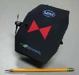
There have been many successful UAV prototypes devel- oped among which is the Black Widow UAV developed in
1999 by AeroVironment that won a award from DARPA. The Black Widow showed an endurance of 30 mins and consists of Auto Pilot. MLB Company has developed a successful UAV i.e. the MLB Trichoid, tests have demonstrated high speeds from 10mph to 60mph and it could sustain stable flight in winds up to 20mph. Another successful UAV working proto- type was developed by Lock-
heed i.e. the MicorSTAR pro- ject, which was tested with 6.0,
9.0, 15.0 and 24.0 inches wing- span with 0.5g navigation sys- tem including processor, it demonstrated altitude of up to
200ft, 30mph maximum veloci- ty with endurance of 20min. MicroSTAR project never en- tered mass production; howev-
er Lockheed continues to develop the autopilot systems for
flown at very long distances for e.g. above 600 feet.
4 SCOPE FOR IMPROVEMENT IN THE EXISTING MODEL
There are issues with the Black widow that the system has a limited endurance and once flown too high, its visibility to the user becomes very low. The system can be improved by using two or more video cameras so that at high altitudes, the user can monitor the video and know where exactly is the UAV flying, however this improvement is within the scope, but leads to an increase in size and weight of the overall sys- tem. The black widow uses a single axis magnetometer, gyro sensor and accelerometer which does not provide very much accurate measurements and in GPS denied areas the accuracy of the inertial measurement unit decreases in time, therefore for much better flight control using 3-axis magnetometers and accelerometers along with 2-axis gyro sensors which will pro- vide accurate measurements. Another major region where the system can have scope for improvement is in achieving two or more degrees of freedom for the flight movements. The black widow UAV prototype has just one degree of freedom that is controlling the yaw rate or heading angle, for improvement
Fig 1. Black Widow [12]
larger UAVs. Other successful
UAV’s has been described in
two more degrees of freedom can be achieved for roll and pitch control movements, making it a system with three de-
[12]. One of the first successful and famous MAV prototype
grees of freedom i.e. yaw, roll and pitch controls. The propul-
IJSER
was the Black window UAV. This UAV has wingspan of about
6in and weighs approximately 100g. It’s a conventional propel-
ler driven UAV i.e. the propeller is driven by electrical Motor
powered by lithium batteries. The structure of airframe of
UAV has rectangular wing with tapered corners as shown in
the Fig 1. The black window has shown an endurance of 30
minutes with maximum range of 1.8km and maximum altitude
of 769feet due to its light weight and small size. The UAV flies
at a speed of 30mph. The inbuilt electronics along with the
UAV is all custom designed consisting of a color camera, video
transmitter, radio control receiver, actuators and an autopilot. The Table 1, shows the performance parameters of the Black Widow UAV. The autopilot consists of a single axis magne- tometer, piezoelectric gyro and static pressure sensors along
with a control processor.
Table 1
Performance Summary of Black Widow [1]
Total Mass | 56.5g |
Loiter drag | 9.4g |
Lift/Drag ratio | 6.0g |
Loiter velocity | 11.2 m/s |
Loiter Lift co-efficient | 0.42 |
Loiter throttle setting | 70% |
Endurance | 33.4 mins |
This autopilot is capable of maintaining airspeed, altitude and heading of UAV. It has just one degree of freedom i.e. yaw movement. One of the issues with black widow is that due to its compact size, it cannot be clearly visible when operated and
sion system used in black widow is a electrical motor driven by lithium batteries, however fuel cells are showing as poten- tial source for next generation UAV’s, since fuel cells have some advantages over the Lithium batteries such as,
• Energy density several times greater than(Lithium Poly- mer) Li-po cells
• No risk of explosion at extreme high temperatures
• Non toxic and no maintenance with infinite shelf life
• Cheaper and light in weight
However there’s still a lot of R&D going in the stream of de-
veloping the most reliable, light weight and high energy densi-
ty fuel cells that can be most suitable for UAV’s that requires
high endurance. Some improvements that can be made out of
the scope is by going for a different design topology such as,
instead of fixed wing topology, a rotary winged topology can
be used that provides higher endurance and can hover or fly at
higher speeds. The performance of fixed wing topology de-
signs can be improved by increasing the wing size, but using
light materials for fabrication with excellent aerodynamics i.e.
good lift to drag ratio, with a powerful propulsion system.
5 PERFORMANCE LIMITS POSED BY SIZE CONSTRAINTS:
One of the main constraints for small size is the physi- cal integration challenge due to the drastic increasing in the functionalities while severe decrease in the system or vehicle size i.e. at and below the 15cm scale size, the concept of “stuff- ing” an airframe with subsystems having complex functionali- ties makes the approach to hardware integration extremely difficult. Small scale propulsion systems will have to satisfy the need or requirement for high power density and high en- ergy density. The power equation for the propeller driven air- craft is
IJSER © 2013 http://www.ijser.org
International Journal of Scientific & Engineering Research, Volume 4, Issue 12, December-2013 601
ISSN 2229-5518
Power (P) = W [CD /CL 3/2] [W/S]1/2 [2/ℓ]1/2 / ŋ (Watt) , where
W = weight (grams)
CD /C L 3/ = Ratio of Lift coefficient (CL ) to Drag coefficient (CD ) S = wing load
ℓ = Altitude (air density) and ŋ = efficiency
Using the power equation relationship provides a good insight
into ways to reduce the power required for propulsion. But
initially it is necessary to have good aerodynamics i.e. high lift
to drag ratio, but the low Reynolds no: wings may only have
1/3 to ¼ the lift to drag ratio of conventional aircrafts. The
power required can be reduced considerably by having low wing loading which is achieved in UAVs by having large wing areas and lightweight vehicles. The Gossamer Albatross de- veloped by the Aerovironment Company had a huge wing
area and low weight so that it could be powered by a very weak engine, but this was done with huge wing spans. In con- trast, the 15 cm limitation means, UAVs may have to maximize area by increasing the wing chord, leading to low aspect ratio configurations. Finally, still in reference to the power equation, there’s nothing more effective than low weight to reduce pow- er requirements. Technologies like MEMS, low power electron- ics, and component multifunctionality or multi tasking will be good enough. High energy density and light-weight power
sources are essential. Battery-based systems will likely power
laws are governing in this domain; a lot of efforts have been made to understand ultralow Reynolds number flight, study- ing the flight of insects whose size is even smaller than NAV. Although aerodynamics at low Reynolds numbers are not clearly understood yet, it is well know that for Reynolds num- bers under 100,000, the aerodynamics efficiency (defined as lift-to-drag ratio) rapidly decreases. During the design process of UAV’s, both the weight budget and the power budget should be carefully monitored. In particular, the total mass of the vehicle should be kept as low as possible, since added weight will increase power consumption.
QFD (QUALITY FUNCTION DEPLOYMENT)
Based on the customer, user demands and the market as- sessment for the given problem statement, the design manger prioritize the customer needs which are important for the mis-
the first generation UAVs, but more exotic technologies like fuel cells are being developed for follow-on systems. If the power and propulsion problems appear daunting, the issue of navigation may be even more so. Large reaches of open air environments may render this problem doable with in-hand technology, but the more demanding environments to which the UAV is uniquely suited are another matter. GPS would be a near-ideal solution, but current systems are much too heavy and too power-intensive for UAV applications. Inertial naviga- tion for UAVs awaits the development of low-drift micro gy- ros and accelerometers. Real time human interaction to pro- vide vehicle stabilization and guidance is being considered for early designs, but performance or other mission constraints may render this solution impractical in some of the more de- manding applications. For example, necessary vehicle agility may well surpass a human operator’s ability to cope with it, and real-time human controls may not be possible except in the simplest of scenarios. Clearly, significant advances in min- iature navigation, guidance and control systems are needed. In the last few years, the miniaturization progress of UAV’s has practically stopped. This mainly happened since there are sev- eral problems such as the physical and technological challeng- es that slow down further miniaturization. The first problem that appears is related aerodynamics related to the low Reyn- olds number for UAV’s. This dimensionless number reflects the ratio between the inertial forces and the viscous forces and is defined as,
Reynolds number = fluid density*speed*size/ viscosity
For UAV’s, both speed and size are several orders of magni-
tude smaller than for large aircrafts. This gives Reynolds num-
ber, less than one-hundred thousand, which is less than one-
tenth of what is common for a full-size aircraft. Flight in this
aerodynamic domain is more difficult, since other physical
sion and transfer them into technical requirements using a
simple Quality Function Deployment (OFD) matrix.
Fig 2. Quality Function Deployment (QFD)
Through this process a set of customer, user requirements
were developed and transferred into engineering characteris-
tics or technical requirement shown in the Fig 2. On the left
IJSER © 2013 http://www.ijser.org
International Journal of Scientific & Engineering Research, Volume 4, Issue 12, December-2013 602
ISSN 2229-5518
side all the customer, user needs are placed which was catego- rized into vehicle performance, interfaces and cost and opera- tional and system performance. Engineering characteristics or technical requirements to meet those customer needs are all listed at the top of QFD. Each of the engineering characteristics is weighed differently by each of the customer needs and as in the customer prioritization. Later all the numbers are added for each technical requirement to figure out the order of im- portance of them. The benefits of the QFD matrix is that the conflicts between technical requirements are clearly shown, the solid filled circle, indicates the user and the technical require- ments are very critical and it is at most important to include in the mission. And this solid circle is rated as 9. The solid trian- gle indicates the requirements are important have in the mis- sion and it is rated as 3. The solid rectangular which is rated 1, indicates the requirements are useful but not so important. In this way all the weights are added and the total score was used to determine the relative importance of all the customer needs.
6 DESIGN SPECIFICATIONS DERIVED
In design specifications the customer needs are defined in- to technical problems that have to be met. The Fig 3 shows the UAV system and its subsystems with allocated functionalities. The system is diverged into three subsystems where subsys- tem1 (Auto Pilot and Communication Unit) is the most critical
munication Unit and it is seen that the technical expertise in embedded systems plays a major role in the Auto Pilot Unit while the RF Engineer plays a major role for the Communica-
tion Unit. The Communication and Imaging unit is used for communication between user (Ground section) and the UAV.
Fig 3. Subsystem Functionalities
(On board section) and also used for monitoring and surveil- lance purpose.
• ENERGY STORAGE UNIT: This subsystem is responsible

IJSER
subsystem followed by subsystem 3 (Propulsion and Air frame
unit) and subsystem 2 (Energy Storage unit).
• AUTO PILOT AND COMMUNICATION UNIT: This sub-
system is responsible for the guidance control, surveil-
lance and automatic navigation on the UAV with no user
input or control. In general the Auto Pilot unit consists of a
set of different sensors, GPS receiver, Actuators and a
brain to control activities i.e. Processor responsible for
guidance control and navigation.
Table 2
Autopilot and Communication Unit Design Specification
Auto Pilot and Commu- nication Unit | Technical Requirements | Technical Expertise Domain |
1. Auto Pilot Unit | -Weight < 200grams (g) -(LxBxH) 20x20x5cms or 7.5x7.5x2 inches (in) -Automatic Navigation -Degrees of freedom : yaw, roll and pitch -High Performance | -Embedded Systems Engi- neer (Major role) and Communica- tions Engineer |
2. Communi- cation Unit | -Radio frequency com- munication -Video/image capture and compression -Guidance control from ground section | -Radio fre- quency (RF) Engineer (Ma- jor role) -Image Pro- cessing Engi- neer |
The Table 2, shows the user needs stated in terms of technical requirements that has to be met for the Autopilot and Com-
for delivering power to other subsystems/components
present in the system. Note that, as the weight of the sys-
tem increases, the power requirement capacity will also
increase and this in turn will increase the package weight
of the power production device. Demands for energy stor- age unit are high energy density, low weight and small size. Technical expertise such as Electrical Engineers and Chemical Engineers are the source of requirement for this
subsystem.
• PROPULSION AND AIRFRAME UNIT: This subsystem is
responsible for lift of the system using mechanical power
that is known as propulsion and it’s also responsible for
the aerodynamics design and avionics of the UAV that is
most suitable for a good lift. Technical Expertise such as
Avionics/Aircraft Design Engineers and Electrical Engi-
neers are the source of requirement for this subsystem.
7 CONCEPTUAL DESIGN PHASE:
In this phase different principles of energy storage devices, Auto Pilot and propulsion are found i.e. Divergent thinking, and all are evaluated converging to the best possible solution to the problems. Thus this phase is classified into con- cept exploration and concept definition.
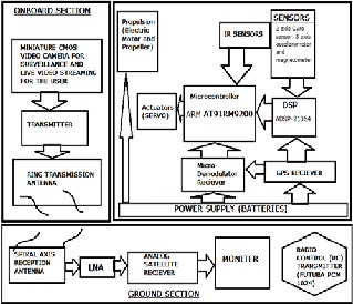
Concept Exploration: It is logical to start off with the most critical subsystem i.e. Auto Pilot and Communication Unit, which involves technical expertise from various domains. The Auto Pilot unit has several sub units (Problems of subsystem 1 is divided) such as Inertial Navigation System, sensors, Actua- tors and processor. The communication unit consists of a video camera, Radio Frequency (RF) Transmitter with a transmission antenna on board, while in ground section, a reception anten- na with a Low Noise Amplifier, a commercial analog satellite receiver (GPS Receiver) and a monitor or screen for displaying
IJSER © 2013 http://www.ijser.org
International Journal of Scientific & Engineering Research, Volume 4, Issue 12, December-2013 603
ISSN 2229-5518
the video captured by the video camera on board for surveil- lance.
1. Auto Pilot and Communication Unit (Subsystem 1)
a. Global Positioning System (GPS): A GPS receiver is used
to receive signals from the satellites regarding the co-
ordinates or location of the UAV and this information is
transmitted to the user in the ground section. The risk
involved in using only GPS to track the position of the
UAV is high in GPS denied areas where the receiver is
not able to detect or receive any signals from the satellite;
in this case Inertial Measurement Units (IMU) comes into
picture.
b. Inertial Measurement Unit (IMU): The IMU consists of a
Gyro sensor for measuring the angular rate of the UAV
and Accelerometers for measuring the velocity of the
UAV. In GPS denied areas, the IMU takes in the last co-
ordinates position values of the GPS and tracks the posi-
tion of the UAV. In general cases a gyro sensor and ac-
celerometer is place on single axis, therefore in GPS de-
nied areas as time goes on, the accuracy of the measure-
ment also gets degraded easily. Gyro’s are responsible
for the roll and pitch movements of the UAV.
c. Sensors: Including Gyro and Accelerometer, additional
sensors are used for flight stability control such as altim-
eter i.e. Barometer for measuring the altitude of the
higher energy density.
3. Propulsion and Airframe Unit (Subsystem 3)
There are two propulsion methods that have shown significant progress in UAV’s, the first one being the elec- tric motor known for its maturity and reliability followed by the Internal combustion engine (ICE) that comes with a engine in which combustion takes place (Air Oxidation) applying force on the blades or propeller. The Electric mo- tor take power from the energy storage unit eg battery in order to spin the propeller.
Concept Definition: The alternate solutions to the defined problems are found, now the best all the solutions are evaluat- ed converging to find and select the best possible solutions.
1. Auto Pilot and Communication Unit:
• Auto Pilot/Inertial Navigation System (INS) : The com- bination of both IMU and GPS together is known as INS. Therefore the GPS is used for locating the position of the UAV and in GPS denied areas the IMU helps determine the path. Issues with single axis gyro sensor and accel- erometer is that the accuracy of the measurements de- grades in time, therefore for better accuracy, the 2 axis gyro’s sensor and 3 axis accelerometers can be used, since 3 axis may increase cost and weight of the system, but if in case the payload supports then 3 axis concept
can be used for better accuracy measurements. Gyro’s
IJSER
UAV, IR sensors for obstacle avoidance and magnetome-
ter sensor responsible for yaw motion and heading an-
gle of the UAV.
d. Processors: It has a microcontroller which is the brain of
the system that is responsible for making decisions for
navigation based on the data it receives from the sensors.
Processors such as ARM.
e. Actuators: Actuators can also be used for controlling the
flight movements e.g. using an actuator at the rudder of
the UAV for controlling yaw rate based on the sensor da-
ta to the micro controller. Actuators can also be used on the air wings/ airlome to control the roll rate of the UAV.
f. Communication Unit: It consists of a miniature sized
CMOS video camera for live video streaming, RF trans-
mitter with antenna to transmit video to the ground sec-
tion, the reception antenna receives the transmitted data
that is demodulated and displayed on the screen or mon-
itor along with data such as position, altitude and head-
ing angle of the UAV. A Radio Controller (RC) Transmit-
ter is used for controlling the UAV using the concept of
Pulse Code Modulation (PCM).
2. Energy Storage Unit (Subsystem 2)
The most mature technology is the battery and one of
the upcoming technologies that show bright future is the
Fuel cells. There are 3 classes of batteries that have been
used in many successful UAV prototypes, they are Nickel
Cadmium (NiCD), Nickel Metal Hydride (NiMH) and re-
cently the Lithium Polymer (Li-po) Battery packs. The bat-
tery pack for NiMH and NiCD can be anywhere between 5
to 7 cells. Fuel cells can be used using fuels such as metha-
nol and has been used few successful prototypes; however
fuel cells are still under research for better efficiency and
used to control the roll and pitch rate, while magnetome-
ter is used for controlling the yaw rate and heading an-
gle. Additional sensors such as IR sensors for obstacle
avoidance and altimeter i.e. barometer can be used to
measure the altitude. The magnetometer sensor
measures the earth’s magnetic field which combined
with the gravity and velocity of the UAV measured by
the accelerometer is used to determine the 3D orientation
of the UAV. A microcontroller ARM has an ARM state
that fetches 32 bit instruction and Thumb state that
fetches 16 bit instruction and also has on chip debugging features. A DSP processor is used to take the data from all the sensors and the GPS, process and fuse this data and inputs it to the ARM processor which is responsible
for making decisions based on that data. Actuators such as servo can be used since they have a shaft that can be positioned to specific angular position by sending coded signal to it. These servo motors are small and extremely powerful for their size and can be used to in the rudder and on the airlomes to control the roll, pitch and yaw rate controls. Note that the UAV should have an inbuilt path plan programmed in the microcontroller so that the UAV can automatically return to the desired location in case of GPS denied areas, where the IMU will guide the UAV to the desired location. For communication Unit,
• On Board: A micro demodulator receiver to receive radio signals from ground section to control the UAV and miniature sized CMOS camera for live vedio feed. RF transmitter with antenna for modulating the input ana- log video from the camera and transmitting it.
• Ground section: A spiral axis directional radiation recep- tion antenna, an HEMT based Low Noise Amplifier (LNA), Monitor or laptop and a satellite receiver (GPS
IJSER © 2013 http://www.ijser.org
International Journal of Scientific & Engineering Research, Volume 4, Issue 12, December-2013 604
ISSN 2229-5518
receiver). LNA is used to amplify the received signal and reception antenna receiver demodulates it for display. A RC transmitter can be used for flight control using PCM. A detailed control design for pitch and roll has been il- lustrated in [7].
2. Energy Storage Unit: The concept of fuel cells is elim- inated due to it being still under development while selecting a mature concept of batteries which has shown potential in many successful prototypes. Bat- teries are used in electrical systems as it’s known for its highest energy density. Note that rechargeable bat- teries have lower energy densities than that of non re- chargeable since many development programs sacri- fice the higher energy density for the batteries with the ability to be reused. Batteries are also light in weight since nowadays its produced with a thin metal foil packaging.
3. Propulsion and Airframe Unit: The concept of Inter- nal Combustion Engine (ICE) is eliminated since it will be too large for the UAV with a wingspan of
7.5inches (in) and its high viscosity of oils and fuel will not allow for proper flow through the small di- ameter valves because of their high surface tension. Fuels such as propane can be used, however as the
ICE becomes smaller in size, lots of improvement are
minimum weight and smallest size must be chosen.
a. Inertial Measurement Unit:
• Miniature Piezoelectric angular rate Gyro sensor: Weight of the sensor is 4.8grams (g) and dimensions are 26(L) x27(B) x11.3 (H) mm. These sensors weigh 4.8g without a plastic casing, therefore with plastic casing the approxi- mate weight of each sensor will be 5g, therefore using two of this sensors will weigh 10g. A 3 axis MEMs based Ac- celerometer, the product measures acceleration with a minimum full-scale range of ±3 g. It can measure the static acceleration of gravity in tilt-sensing applications, as well as dynamic acceleration resulting from motion, shock, or vibration.
Note that we also get miniature sized MEM’s based readily available IMU i.e. MEMS HG1930 IMU that is developed by Honeywell as illustrated in [2].
• GPS Module: All in one mini size GPS module has been developed by the company RoadComm.Inc. It has high performance signal processor with a LAN and high sensi- tivity to satellite signal. It consumes power of approx
0.5W. Its weight is 23grams and dimensions
46mm*67mm*9MM.
• Risk involved with RoadComm GPS module: it is very
bulky for MAV and weighs more i.e. 23grams, its increase
in weight is due to the inbuilt DSP processor along with
IJSER
needed to provide enough power out of the motor ,
thus ICE is highly unreliable. Hence the concept of
Electric motors for propulsion is best, since Electric
motors is a mature concept known for its reliability,
low noise, low vibrations, small size and high efficien-
cy, it is more practical to use Electrical motors for the
UAV’s. The most common method of propulsion for
UAV’s is by using rotary propellers which are set in
motion by the electrical motors and propellers with large diameter provides better efficiency, however Stanford researchers have designed and tested smaller propellers with diameters as low as 1.5cm illustrated in [16] .The Airframe unit is responsible for the design of the structure of the UAV depending on the number of propellers used. Miniature servomotors can be used for the rudder for yaw motion control and a actuator on each of the UAV’s airlome’s or elevons (control surfaces) for controlling the roll and pitch rate. Most propeller-driven UAVs fly at high speeds because propeller efficiencies are best at high Reynolds num- ber. High chord Reynolds number is generally achieved using high RPMs
8 ADVANCED DEVELOPMENT PHASE
The concept for implementing the functionalities of each subsystem has been clearly defined in the conceptual design phase. In the advanced development phase, the components responsible for implementing the concepts are looked into de- tail and evaluated.
1. Auto Pilot and Communication Unit: The weight of this subsystem should not exceed 200 grams (gm), as is the constraint that needs to be met; therefore components with
GPS, however since we shall be using a separate DSP pro-
cessor for data fusion of the GPS data and sensor data.
Therefore we discard the use of RoadComm GPS module
and look toward using a lighter and smaller GPS module
developed by the company Trimbles.
The Trimbles new lasses SQ Gps module uses low power of
3.3V and is a micro size GPS solution for UAVs, whose dimen-
sions are 26mm(W)*26mm(L)*6mm(H) and its weight is about
5.7 grams. The performance specifications and other character-
istics of this GPS module have been illustrated in [Trimble
Navigation Limited, 2002]. The weight and size of this GPS module is much lesser than that of RoadComm GPS module, due to the exclusion of the DSP processor.
• Sensors: For Altimeter, the MPXxx611A series sensor from free scale semiconductor shall be used. These sen- sors are ideally suited for microprocessor or microcon- trollers based system. It operates at 15 to 115kPa range with an output of 0.2 to 4.7V output. These sensors are available in super small outline packaging with an ap- proximate weight of 5g. The Xtrinsic MAG3110 3-axis magnetometer sensor developed by the free scale semi- conductor, its weight is approximately 4.6g and is very small in size that features I2C serial interface output and smart embedded functions. Its dimensions are
2mm(L)*2mm(B)*0.85mm(H) with miniature packaged IR sensors with high power LEDs can be used such as IR LED L6895-10 has a wavelength of 940nm.The weight of the IR sensors used depends on the number of sensors used; hence it should not exceed 12g with 3 or more IR sensors. It’s a 10 pin package and requires low power supply of 1.95V to 3.5V (Vdd).
• Microcontroller and DSP Processor: The ARMTDMI9 microcontroller is chosen over the ARMTDMI7 due to
IJSER © 2013 http://www.ijser.org
International Journal of Scientific & Engineering Research, Volume 4, Issue 12, December-2013 605
ISSN 2229-5518
its improvement in clock frequency, 5 stage pipelining and enhanced load and store architecture which pro- vide faster processing of instructions. The AT91RM9200 belongs to the ARM9 family developed developed by ATMEL Company. The AT91RM9200 main features are: (1) 32-bit fixed point and 180MHz frequency (2) 5 USART ports used to collect GPS data for communication purpose (3) 4SPI peripherals used to collect A/D converter data (4) 16 bit tim- ers/counters, used to collect radio receiver signals and used for flight control (5) It has FLASH, SDRAM and other storage units, Ethernet and USB 2.0 interface for high speed communication with the outside. A DSP processor is used for data fusion from the sensors and the GPS, the processor used is ADSP-21364 manufac- tured by the company ADI. Its features are 32 bit float point and 333 MHz. The weight of the DSP processor and the microcontroller should be within 40 grams. Ac- tuators such as the lightweight servo (Pico STD) weighs 5.4 g without plastic case, has the dimensions of 22.8x 9.5x 15.5 mm, and can output the torque of
0.53 kg-cm, therefore 3 to 4 actuators weigh approxi- mately 25grams.
b. Communication Unit: The onboard CMOS video camera
weighs 4.5g, Dimensions of 15x15x20 mm, resolution of
to increase the output of the battery, a DC to DC
buck-boost converter can be used.
DESIGN AND SIMULATION OF DC-DC BOOST CONVERTER (RISK MITIGATION):
Assume that the Input voltage (Vin) to the boost converter i.e. the DC output from the battery in the UAV is,
Vin = 12V
Required output voltage (Vo)
Vo = 24V
Frequency (f)
f = 16 KHz
Power semiconductor device used is IGBT, which provides better efficiency for a low frequency application i.e. below
20KH2, thus switching frequency selected is 16 KHz. Duty cycle (D)
D = 1 – Vin/Vo
D = 1 – 12V/24V
= 0.5
= 50%
Assume current (I) flowing across the load Resistance
(RL ) is, I = 2Amps
Therefore,
352x288 pixels and powIer of J100mW. It aSlso consists of ER
micro demodulator receiver to receive the radio signals
from the RF transmitter and it weighs 5.4g and dimensions
of 20x30x9.5mm. The RF transmitter weighs 8g with a ring
transmission antenna of frequency 1.18GHz-1.45GHz with
output power of 56mW and input power of 7.2Volts (V) to
10.8V. On ground section, a spiral reception antenna with
LNA whose spiral diameter is 67mm and frequency of an-
tenna is 1.2GHz-1.5GHz and LNA frequency of 400 to
1500MHz with a gain of 15db. A Futuba PCM 1024 Radio
Controller (RC) is used to communicate with onboard.
2. Energy Storage Unit: There are different classes of batter-
ies that can be used such as lithium-polymer (Lipo), NiCD
and NiMH batteries, however lipo batteries are rechargea-
ble batteries while NiCD and NiMH batteries are non-
rechargeable. These batteries are compact in size and their
weight differs from each other. The correlation or relation
between the battery weight and its capacity (mAH) as
shown in [12]. The NiCD and NiMH batteries have been
used in MAV prototypes such as TH380 and TH360 and
have been tested as illustrated in [7].
• Power Distribution Risk: It is necessary to know the
voltage drop across all the components and how power can be distributed in the network or system. In case if the power requirement has exceeded the limit and the battery output is not sufficient, then increas-
ing the capacity (mAh) of the battery will lead to in- crease in the size and weight of the battery, therefore to overcome this issue, it is necessary to use a buck- boost converter to boost the output of the battery, this will save time, and money for increasing the capacity of the battery and provides reduced weight and also gives the desired boosted output voltage. Therefore
RL = Vo/I
= 24V/2 Amps
= 12Ω.
The minimum inductance (L) required for the converter to op- erate in continuous current mode is given by,
Lccm = D (1-D)2 R / 2*f
= 0.5(1-0.5) 2 * 12 Ω /2 * 16 KHz
= 46.87 μH
Therefore,
L = 2 * Lccm
= 2 * 46.87 uH
= 93.74 uH
Ripple factor (r)
r = deltaVo/ Vo
= Vmax – Vmin / Vo
= 25V – 23V / 24V
= 0.083
Capacitance C = D / R*r*f
Cccm = 0.5 / 12 Ω *0.083 * 16 KHz
= 31.3 μF
Therefore C = 2*Cccm
= 62.6 μF
For Pulse generator used to trigger the IGBT in the converter,
Period (seconds) = 1/f
= 1/16 KHz
= 0.0625 ms
The calculated component values are used to simulate the
boost and buck-boost converter using the software tool known
as MATLAB r2009b.
IJSER © 2013 http://www.ijser.org
International Journal of Scientific & Engineering Research, Volume 4, Issue 12, December-2013 606
ISSN 2229-5518
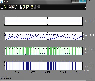
Fig 4. DC to DC Boost Converter
The Fig 4 shows the circuit design of the boost converter. In boost converter, when the IGBT switch is closed, inductor
charges or stores current while the capacitor discharges and
er a new coreless motor as illustrated in [7] proved to be more powerful along with its small size and light weight.
Both the drive motor and the coreless motor can operate anywhere with batteries of 5 to 7 cells at a power range of
8 to 15Watts (W) and are more efficient at the speed of
9000r/min-12000r/min.
IJSEFiRg 6. System (UAV) Integration
when the IGBT is open switch, the inductor current flows through the diode and charges the capacitor and flows across the load resistance.
Fig 5. Boost Converter Ouput
The Fig 5, shows the scope output simulation of the designed boost converter that boosts the input voltage from 12 Volts to an output voltage of 24 volts. But in the simulation it is seen that the input is boosted to only about 22.5 Volts and not
24Volts, and this is due to the voltage drop of 2Volts across the
IGBT and diode.
3. Propulsion Unit: Direct drive motors can be used such as motor rated with 6V with a speed of 13000r/min. Howev-
The Fig 6, shows the architecture of the UAV system in which,
the IR sensors are directly connected to the ARM, while the
Sensors and the GPS data is fused (sampling and quantization)
in the DSP processor and then inputs to the ARM, which makes a decision based on this data and powers the actuators for navigation control. The Onboard section transmits video to the user to see and the Ground section consists of RC transistor
to send radio waves which is received by the micro demodula- tor and then input to the ARM for navigation control. All the components must undergo failure analysis to avoid risks and improve reliability of the whole system.
A common failure fault that is encountered during electrical testing is the components damage in a system that is caused due to electrical overstress. Electrical Over-Stress (EOS) is a term used to describe the thermal damage that may occur when an electronic device is subjected to a current or voltage that is beyond the specification limits of the device. During the testing the Voltage v/s Current (VI) characteristics curve is drawn or traced for the input to each components present in the system in order to identify if there’s any electrical input overstress have occurred
The identified failed parts VI characteristics can be compared to the VI characteristics of the good part and if there’s any de- viation from the desired response, then the test results are not- ed and recorded for later examination of that failed part in order to rectify the fault. In industries, all systems that are de- veloped have to undergo environmental tests, mechanical tests and electrical tests in order to detect faults, analyze and rectify them, these test procedures have been illustrated in [5].
IJSER © 2013 http://www.ijser.org
International Journal of Scientific & Engineering Research, Volume 4, Issue 12, December-2013 607
ISSN 2229-5518
checking if the components can give an accurate fit, if not some modifications are to be done.
1. Auto Pilot and Communication Unit
The Table 3, shows the different components used in the auto pilot & communication unit, details regarding the components specifications, operating conditions & the packaging details.
Table 3 Subsystem 1 component specifications
DD(CORE)
age Vs=4.75V to 5.25V Supply cur- rent
Is =6mA
and
Tempera- ture range :
-40oC to
+120oC
Pressure range :
Durable Thermopas- tic (PPS)
and surface Mount Package
Transmitter with ring
transmis- - sion anten-
na
Max=10mA Sensitivity
45mV/kpa
15kpa to
115kpa
(SSOP/SOP
)
9 DETAILED OR FINAL DESIGN PHASE
In this phase, a manufacturing diagram for the UAV architec- ture is developed and issues such as material characteristics i.e. Thermal and Electrical properties of the components are checked for their feasibility for manufacturing. And then the integration or interfacing of all the components are done by
After windowing in through all the components it was real- ized that the use of IR sensors may have some serious issues.
IJSER © 2013 http://www.ijser.org
International Journal of Scientific & Engineering Research, Volume 4, Issue 12, December-2013 608
ISSN 2229-5518
The IR sensors have some serious limitations for real time practical implementation for UAV’s such as,
• Accuracy is less
• IR Sensors cannot be used in the outside in sunlight, if
exposed to sunlight, results will fluctuate causing perfor-
mance degradation
These issues can be resolved by using ultrasonic sensors,
which may be slightly more expensive than IR sensors, but it
can detect accurate distances of obstacles, no matter what col-
our they are, therefore ultrasonic sensors are accurate and do
tion of pulse position modulation or pulse code modulation.
1. Energy Storage Unit:
While windowing in, the details regarding the lithium poly- mer batteries were analysed and some issues such as:
• Low energy density
• High Cost
• Risk of explosion at high operating temperatures
• Weight increases drastically with increase in capacity, thus
again leading to increase in the cost.
The above issues can be solved by developing NiCD or NiMH
batteries. 5 cells 6V with a capacity 300mAh battery pack can
be used and it’s known for its ability to deliver much higher currents compared to the smaller sized cells due to its low in- ternal resistance. Another battery pack that is light in weight and smaller in size that can actually be the most suitable ener-
gy storage unit is the NiMH battery pack that has a capacity of
600mAh and weighs only 21g and dimensions of D =
71x30x5mm (LxBxH). Some methods to reduce the power re-
quirement can be obtained by manipulation of parameters in
the power equation such as,
Power (P) = W [CD /CL 3/2] [W/S]1/2 [2/ℓ]1/2 / ŋ (Watt) , where
• W = weight (grams), minimize weight by using micro fab- rication process and multitasking of components for less critical functionalities
• CD /C L 3/ = Ratio of Lift coefficient (CL ) to Drag coefficient (C ), It is the Maximum Endurance parameter, a thin cambered airfoil shall provide low Reynolds number and the lift to drag coefficient parameters can be maximized.
• S = wing load, minimize wing loading and its weight while increasing its surface area limited to the size con- straint.
• ℓ = Altitude (air density), Maximize altitude to maximize air density.
• ŋ = efficiency, maximize propeller efficiency such as opti- mizing the speed, size and type to suit the operational
not cause fluctuations when exposed to sunlight. Another is-
sue that can limit the performance is the absence of the on
board heatsink for the Motors, since losses due to heat dissipa-
tion is more in the motors, so using a heat sink will reduce the
losses and improve the overall performance of the UAV.
Table 3
Weight Summary of Subsystem 1
The Table 4, show the weight of all the components on board of the subsystem 1 i.e. Autopilot and Communication Unit. Some weight of the components mentioned in the subsystem 1 true while some are approximated to the closed weighing val- ue of the components, however the overall weight of the sub- system 1 is approximated to 101.7g, which may reach a maxi- mum of 125grams with the plastic casing of some components but the constraint of building this subsystem weighing within
200 grams can be met successfully. The RC transmitter on ground section is the Futuba PCM 1024 which has some ad- vanced features such as 8-channel system, with 1024 modula-
needs.
2. Propulsion and Airframe Unit:
It is necessary to test the UAV prototypes using both the pro-
pulsion methods i.e. Direct drive motor and coreless motors,
however it is more suitable to use coreless motors since its known for its smaller size and light weight compared to the drive motors. These motors can show operate with 5 to 7 cells NiMH or NiCD batteries. The speed of the Motor can be con- trolled by using Pulse Width Modulation (PWM) techniques such as by using an Astable NE555 multi-vibrator, through which the width of the pulses can be varied by varying the resistance potentiometer in order to vary the speed of the mo- tor. The weight of the motor along with a single propeller is approximately considered as 34g. Several wing platforms can be used for UAV designs, such as rectangular, elliptical, ta- pered and triangle wings. Major factors that should be consid- ered while choosing the wing platform is the tip-stalling and its ease or feasibility for wing fabrication and its assembly. The proposed airfoil section used to obtain a moderate lift to drag ratio within the interested Reynolds number range i.e. 1*105 to
IJSER © 2013 http://www.ijser.org
International Journal of Scientific & Engineering Research, Volume 4, Issue 12, December-2013 609
ISSN 2229-5518
3*105 and to manufacture of the wings, the coordinates (x, y) of an airfoil are obtained by visual software as illustrated in [7]. The UAV should be tested be tested for 3 kinds of propellers and they are propeller 1 with an 8-in diameter and 3.8-in pitch (mm), propeller 2 with a 7-in diameter and 4-in pitch and pro- peller 3 with 7-in diameter and 6-in pitch. In this the probabil- ity of the propeller 1 is to generate the smallest static thrust, propeller 2 generates a moderate thrust while propeller 3 has advantage of static performance over the others, however all the 3 propellers performance must be considered while testing. The weight of the Airframe unit is assumed to be within 32g and an approximation to 28.7g and the weight of the structure of UAV shall be within 37g.
Table 4
Weight Summary of the Overall System (UAV)
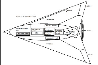
Fig 7. UAV Manufacturing Drawing
These actuators are powered by the microcontroller for con- trolling the movement of the flight depending on the data re- ceived by the sensors and the GPS to the microcontroller. Note that the ARM should be programmed such that, when the GPS signal is cut off, the INS should be able to navigate the UAV automatically back to the place where the user is located, hence a preplanned path must be programmed within the
ARM. For fabrication of the UAV, it is necessary to use materi-
als that are light in weight as well as good stiffness and should provide ease of fabrication. Few materials that can be used are balsa, Styrofoam, plywood, carbon fiber and kelvar show a good fit for fabrication of the UAV. Therefore for the above UAV, carbon fiber strips can be used for wingspans and ele- vons etc. Note that most of the aircrafts fly at Reynolds num- bers in the millions, almost 100 million for a Boeing 747, how-
The Table 5 shows the payload allocation for each subsystem, where it is seen that the Auto Pilot and Communication Unit weighs maximum of 101.7 g followed by the Propulsion and Airframe Unit i.e. 40.7g. The overall weight of the whole sys- tem will approximately come within 200g and a certain toler- ance weight is allocated as structure in which fabrication and materials weight are considered. The Fig 7 shows the design of the UAV that is feasible for manufacturing. It shows the alloca- tion of the subsystems within the UAV. It consists of a single powerful electrical motor that drives the propeller and there are three Actuators present in the system. The two elevons are controlled by the actuators for the roll movement of the flight, while one actuator is used to control the rudder, which in turn helps in controlling the yaw rate of the flight
ever Reynolds no above 200,000 developed for the airfoils are
inappropriate for designing UAV wings. Once the UAV proto-
type is developed, it is necessary to perform vibrations testing
and analysis using the RT pro software and also Thermal anal-
ysis using software tools such as Icepack.
CONCLUSION
During the need analysis phase, the user and customer needs were defined with the analysis of the market size and its strength arriving to the desired design specification of subsys- tem functionalities i.e. Auto Pilot and Communication Unit, Energy storage Unit and Propulsion system and Airframe Unit. The concept of divergent thinking was applied during concept exploration and convergent thinking during the con- cept definition phase. Once the right concepts had been select- ed then components required to meet the functional require- ments were identified and also risks associated with the com- ponents were identified for which alternative solutions are developed i.e. Risk Mitigation as well as the architecture for the whole system is developed. In final detailed design the design feasible for manufacturing is developed and some fab- rication details regarding the system and technical description on how to reduce power requirements by the variation of its parameters such as lift to drag coefficient, weight of the sys- tem, surface area of the wing etc is discussed.
IJSER © 2013 http://www.ijser.org
International Journal of Scientific & Engineering Research, Volume 4, Issue 12, December-2013 610
ISSN 2229-5518
REFERENCES
[1] Amira Sharon, Olivier L. de Weck and Dov Dori (2010), “Project Management vs. Systems Engineering Management: A Practitioners” View on Integrating the Project and Product Domains” Massachusetts Institute of Technology, December.
[2] Benjamin B. Mohr & David L. Fitzpatrick (2008), “Micro Air
Vehicle Navigation System” Honeywell Laboratories, USA.
[3] Clark N. Taylor (2008), “Fusion of Inertial, Vision, and Air
Pressure Sensors for MAV Navigation” Korea, August.
[4] Cunxiao Miao & Jiancheng Fang “The design and implement of micro autopilot system for low-altitude mapping of MAV” Bei- Hang University, China.
[5] Department Of Defense Test Method Standard Microcir- cuits (2004), “Mil-Std-883f” 31 December, USA.
[6] Gerardo Flores, Shuting Zhou, Rogelio Lozano & Pedro Castillo (2013), “A Vision and GPS-Based Real-Time Trajectory Planning for MAV in Unknown Urban Environments” Atlanta, May.
[7] Huaiyu Wu,, Dong Sun & Zhaoying Zhou (2004), “Micro
Air Vehicle: Configuration, Analysis, Fabrication, and Test” Hong
Kong, March.
[8] Item Software, Inc (2007) ,“Reliability Prediction Basics” USA. [9] Lorenz Meier, Petri Tanskanen, Friedrich Fraundorfer and Marc Pollefeys “PIXHAWK: A System for Autonomous Flight using Onboard Computer Vision” Zurich, Switzerland.
[10] Mr T. Spoerry & Dr K.C. Wong (2006), “Design And Devel-
opment Of A Micro Air Vehicle (Μav) Concept: Project Bidule”
Estaca, France.
[11] S. Winkler, M. Buschmann, L. Kruger, H.-W. Schulz, P.
Vorsmann (2007), “Multiple Sensor Fusion for Autonomous Mini and Micro Aerial Vehicle Navigation” Germany.
[12] Timothy Kinkaid (2006), “Study of Micro-sized Technology,
Micro Air Vehicles, and Design of a Payload Carrying Flapping Mi- cro Air Vehicle” US Naval Academy, March.
[13]William J. Vigrass (1997), “Calculation of Semiconductor
Failure Rates” Indianapolis, 19-22 October.
[14] Wilton Workman, “Failure Analysis Techniques” Texas In-
struments Inc, Texas.
[15] William A. Davis (2007), “Nano Air Vehicles A Technology
Forecast” Air War College, April.
[16] Ilan Kro, Fritz B Prinz, “The Mesicopter:A Meso Scale Flight
Vehicle NIAC phase I Final Report” ,Stanford University, Stan-
ford.
IJSER © 2013 http://www.ijser.org