International Journal of Scientific & Engineering Research, Volume 4, Issue 1Ř, mber-2013
ISSN 2229-5518
Synchronizer Performance Malfunction In
Manual Gearboxes – An Overview
UMESH WAZIR
Mechanical Engineering ADE
University Of Petroleum & Energy Studies , Bidholi
Dehradun, 248 007 , Uttarakhand - India
1455
Abstract—Speed changes in manual transmissions are made by shifting toothed cone clutches rather than individual gears as the gears are always in mesh. Today, synchronizers are used in all manual transmissions including trucks and commercial v ehicles. Most synchronizing systems are patented or covered under copyright act. Little technical information is available in public domain.This paper is offered as a guide to acquaint and familiarize the engineer with various gear synchronizing mechanisms used in today ’s ve- hicles. A review giving application, features and limitations of the current level of technology is presented
Synchronizer performance , performance malfunction and reasons there off are addressed in detail. And finally the reader is also ac- quainted with the future trends in this area. An understanding of this and the related problems would guide the designer towards a practical design of a gearbox.
Index Terms : Manual Synchronizer, Performance, Malfunction, Gear Shift, Synchronization, Gear Box
1 2 3 5,6 7
—————————— I———J————-- -- S-- ER
1.0 INTRODUCTION
A gearbox is used to alternate the rotational speed and torque that the engine delivers to the drive wheels of a vehicle. It uses differ- ent gear ratios to achieve it.
The synchronizer’s job is to bring the next gear ratio (up shift or down shift) up to speed so that out put shaft and the gears are at the same speed to allow for a smooth gear change.
Earlier, when "synchronizers" were not used one had to double- clutch for allowing gear shift on the go. At every gear shift one had to press and release the clutch twice, hence the name "double-clutching." It was an art to avoid gear clashing
Modern cars use Blocker Ring Synchronizers in order to avoid the need for double-clutching. [14]
2.0 Function Of A Synchronizer
2.1 Synchronizer objective
Synchronizer forms a mechanical part of the gearbox. Its objec- tive is to ensure speed of the on coming gear to be same as that of synchronizing hub.(attached to the output shaft). Friction cones are used to bring about this synchronization of gear and the hub
While speeds are being synchronized no engagement of dog teeth of gear takes place. So long the synchronization ( moment bal- ance) is not achieved , the blocker ring prevents any engagement of the sleeve and the dog teeth. This is the baulk / blocker ring principle. Fig 1.
Each manufacturer's synchronizer is slightly different than the others, but the basic idea is the same.
IJSER © 2013
http://www.ijser.or
4
Fig 1.
1 Gear; 2 Dog Teeth; 3 Synchronizing Ring ; 4 Synchronizing Hub;
5. Detent Spring; 6 Detent Ball; 7. Shift Sleeve Fig Source [6]
2 3 7
a) b) c)
Fig 2.
a) Sleeve (7) moves from neutral to detent (synchronizing) posi- tion, starts building detent (synchronizing) load
b) Synchronizing ring (3) indexes, sleeve engages chamfer of the ring, Cone Torque builds, synchronizing begins. Lock up with dog teeth (2) prevented
c) Gear (1) speed relative to ring (3)and sleeve (7)falls to zero, synchronization complete, chamfers index and sleeve locks up with Dog Teeth (2)
International Journal of Scientific & Engineering Research Volume 4, Issue 1Řǰȱ ȬŘŖŗřȱ
ISSN 2229-5518
1456
The basic operation of the synchronizer from neutral to engage- ment is as follows Fig 2.
Sleeve moves from neutral to detent (synchronising) posi- tion, starts building detent (synchronizing) load
Blocker ring indexes, sleeve engages chamfer of the ring, Cone Torque Builds, synchronizing begins
Gear speed relative to ring and sleeve falls to zero, synchro- nization complete, chamfers index and sleeve locks up
2.2 Fundamental equations
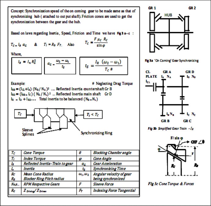
Simple laws of Inertia, Dynamic friction, Speed Change and en- gagement time help optimize synchronizing [1], [4].
Reflected Inertia – Reflected inertia is the total inertia the synchronizer has to synchronize and is a function of mass, radial distance and gear ratio.
Cone torque – The cone torque, also called synchronization tor- que, is the result of the friction force between the conical surfaces in the synchronizer and gear generated as a result of external engagement effort
Index torque – Index torque arises from the shift sleeve’s chamfered teeth applying an axial force on the chamfered teeth. ( As a consequence of driver shift effort). Index torque generated opposes cone torque. Objective – Moment balance
IJSER
International Journal of Scientific & Engineering Research Volume 4, Issue 1Řǰȱ ȬŘŖŗřȱ
ISSN 2229-5518
1457
3.0 Common Types Of Synchronizer Mechanisms
Presently most widely used type of synchronizer is the Blocker Ring Synchronizer which has a mechanism that prevents the coupling teeth engagement before completion of synchronization; a distinct disadvantage suffered by its predecessor – The Con- stant load type synchronizers.
The Blocker ring Synchronizers are categorized into two types –
the Strut and the Pin type
To enhance the synchronizing torque, some synchronizers em- ploy two or more synchronizing cones e.g. Dual or multi cone synchronizers
3.1 Constant Load Type Synchronizer
The earliest form of synchronizer Fig 4, commonly used in au- tomotive gearboxes is known as the Constant Load Type [5] Thrust between the cones is applied by the outer hub initiated by the sleeve movement by the driver. Spring/ball arrangement en- sures the detent load. The main disadvantage of the constant load synchronizer is that it is relatively easy to overcome the detent and try to engage the coupling teeth before synchronization
Good service history
Very low noise level
Low capacity if design space is limited
Requires adjacent gears to be replaced for synchronizer re- placement
3 5,6 3
1 2 4 7 1
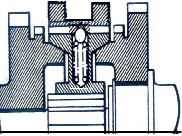
Fig4 Constant Load
Synchronizer.
Note absence Of Synchro- nizing Ring ref Fig1
The most widely used type of synchronizer, in automotive appli- cation, is termed the Blocker ring Synchronizer. This is similar to the Constant Load type but with the addition of a mechanism that mechanically prevents the coupling teeth engaging before syn- chronization is complete.
The parts of the Block Type Synchronizer are as shown in Fig 5. During Synchronization, the sleeve is moved towards the selected gear pushing the blocking ring to the left. The ring contacts the shoulder of the driven gear and begins to synchronize the speeds of the parts.
To complete the shift, the sleeve teeth pass through the blocking ring teeth and mesh with clutch teeth / dog teeth on the driven gear.
Most widely used in passenger cars and light duty trucks. Gener- ally not used in large vehicles, due to excessive inertia involved in the system. Many companies use this type in their passenger cars and light duty trucks. Its main features are:
Very sharp engagement (which is good and is preferred )
Less sensitive to tolerance stack-up

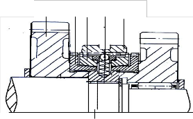
Fig5 Strut Type Synchronizer Fig Source [6]
Strut Type Synchronizer 1 Gear; 2 Dog Teeth; 3 Synchroniz- ing Ring ; 4 Synchronizing Hub; 5 Detent Spring; 6 Detent Ball; 7 Shift Sleeve
Sleeve (7) Strut (6) Pressed by spring (5) locate in the sleeve detent. Speed difference between gear (1) and Synchro hub (4) and the friction drag moment between the cones make the syn ring 3 to index and chamfers of sleeve 7 and & synchronising ring 3 engage. Synchro- nising begins.
So long speeds are different the Cone toque will be greater than Index torque No shifting.
With axial force continuing to act, the speeds equalize and cone torque reduces to zero. Synchronising ring al- lows the sleeve to index -Tooth against Tooth space. Sleeve splines engage the dog teeth roofed ends and
locks. Synchronizing ends
IJSER © 2013
http://www.ijser.org
International Journal of Scientific & Engineering Research Volume 4, Issue 1Řǰȱ ȬŘŖŗřȱ
ISSN 2229-5518
1458
3.3 Pin Type Blocker Synchronizer
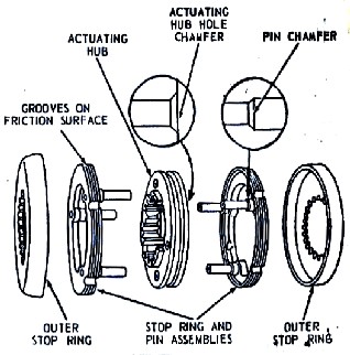
Fig 6 illustrates a pin type synchronizer. The actuating hub is splined to the shaft and rotates with it. The outer ring is splined to the ends of the gears.
The Stop Ring and Pin assembly are loosely pinned to the actuat- ing hub. When the actuating hub is moved to either the right or left, the stop ring and pin assemblies hold the loose fitting pin against the side of the holes in the actuating hub [4]
The actuating hub is prevented from engaging the gear by the chamfered shoulder on the stop ring and the pin assembly. When all parts are rotating on the same, the force between the pin and the actuating hub is reduced.
The hub can then move over the large base of the pins and inter- nal splines on the hub can engage the splines on the gear.
Slight chamfers on the pin and the actuating hub as well as rounded ends of the splines on the hub and the gear, permit these parts to align themselves and mesh easily. Medium duty trucks application. Its main features:
Low cost
IJSER
Highest potential brake capacity for given space
Low cost to service (may not require adjacent gear replace- ment)
Less positive engagement feel and some engagement
‘’click’’ noise
May require shimming in assembly
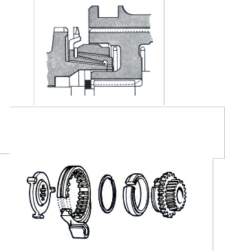
3.4 Disk And Plate Type Synchronizer
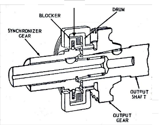
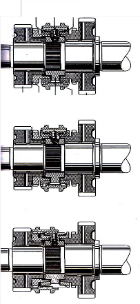
This synchronizer uses Friction Disks and Plates to ring both gears to the same speed for engaging. the blocker (2) rides on and is driven by synchronizer gear (1). Synchronizer drum (4) is dri- ven by the output gear (6). The synchronizer disks (3) are held by
the drum and the separator plates (7) are held by the blockers. 1
When the shift fork moves the drum forward , the synchronizer disks and the separator plates make contact as shown. The block- er moves into locked position on synchronizer gear.
The extra forward motion of the shifter of the tends to compress the disks and the plates to match the speed of the synchronizer gear & blocker and output gear. Once the speed are synchronized, the thrust force locking the blocker in the synchronizer gear is relieved and blocker backs out letting the drum to move forward and engage both gear Its main features:
Synchronizer action is almost instantaneous
Needs wider case to accommodate disk and plate and drum assembly
Larger system inertia capability
Fig 6 Pin Type Synchronizer
2 3,7
4
5
6
Fig 7 Disc Type Synchronizer
IJSER © 2013
http://www.ijser.org
International Journal of Scientific & Engineering Research Volume 4, Issue 1Řǰȱ ȬŘŖŗřȱ
ISSN 2229-5518
1459
3.5 Others
Synchronizers such as the Porsche type, Fig 9, employ a split- ring friction element which expands under the influence of the synchronizing torque there by increasing the interface pressure which further increases the synchronizing torque. Porsche type synchronizer, although powerful do suffer problems related to material variation and dimensional integrity.
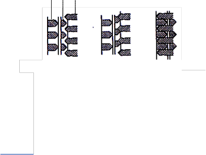
Other synchronizers employ multiple cones Fig 8 to enhance the synchronizing torque but are, in essence, the same as the Strut type synchronizer
out the synchronizing period.
- The synchronizing force is applied instantaneously at the beginning of the synchronizing period and remains constant throughout.
- The drag torques are independent of speed across the speed range involved and so remain constant throughout the synchro- nizing period.
These assumptions affect the accuracy of the calculation in dif- ferent ways, according to the type of shift, i.e. up-shifts or down- shifts. the assumption that the synchronizing force is applied in- stantaneously at the beginning of the synchronization period ig- nores the effect of oil drag in the period between the current gear being disengaged and the cones coming together. for an up-shift, the drag trends to synchronize the cone elements whereas for a down-shift the drag increases the differential speed of the cone elements. therefore the theory will predict shorter synchroniza- tion times for up-shifts, for a given shift lever force.
The other major assumption, that the dynamic coefficient of fric- tion remains constant throughout the synchronization period, has the greatest effect at the beginning of synchronization when the
treads and wiper grooves are clearing the oil from the surface, the
IJSER
Fig 8 Multi Cone System.
Synchronizing torques on individual cones add together to produce a more powerful torque for a given shift lever load Fig Source [ 5]
Fig 9 Porsche type.
Split Synchronizer gear has a self wrapping effect and is very powerful. synchronizer acts on inside diameter. On synchronizing the ring releases automatically – Fig Source[ 5]
4.0 Synchronizer Performance
The traditional theory of gears shifting has been well documented in several technical papers, and the reader is directed to see refer- ences [1], [2], [14] and [5].
However, the effect on the performance malfunction of the sim- plifying assumption, used in the derivation of the traditional theory is summarized
The simplifying assumptions made in the derivation of the theory are:
- The dynamic coefficient of friction remains constant through-
dynamic coefficient of friction remains sensibly constant over the
operating range of speeds and temperatures usually encountered in synchronizer operation. the effect of this assumption is to cause the theory to predict lower levels of synchronizer force for both down-shifts and up-shifts.
Lower lubricant temperatures will accentuate the effects de- scribed above, because lower temperatures result in high oil vis- cosity, which in turn increases gear box drag and the time re- quired by the threads and wiper grooves to clear the oil from the cone surface.
Although the theory cannot be expected to give an accurate pre- diction of the absolute synchronizer force required to achieve a given synchronization time, after the oil has been cleared from the surface It can be used to predict the effect of changes in geo- metry or friction coefficient.
4.1 What is Performance Malfunction
Clash : Occurs when the synchronizer cones still have relative speed after the block mechanism has moved aside to allow the sleeve spline to pass
Hard Shifting: Occurs when synchronizer design torque is not achieved during synchronization.. Either significant malfunc- tion, or it is an incorrect design.
4.1.1 Clash
Clash occurs when the synchronizer cones still have relative speed after the baulk mechanism has moved aside to allow the
IJSER © 2013
http://www.ijser.org
International Journal of Scientific & Engineering Research Volume 4, Issue 1Řǰȱ ȬŘŖŗřȱ
ISSN 2229-5518
1460
sleeve spline to pass. The symptoms of clash are a grating sound from the gearbox during shift, caused by the coupling teeth running into each other. A distinction is made between full clash where the relative speed of the cones is high, and partial clash where the relative speed of the cones has been substantially re- duced by their operation.
General causes of clash are:
Low friction torque between cup and cone.
High torque to move the sleeve relative to synchronizing rings (Indexing).
Eccentric loading of cones.
Excessive drag after synchronization.
Unfavourable tolerance build-up on components or excessive cone wear preventing the cones from engaging.
4.1.2 Hard Shifting
High shift effort during synchronization is due to either a signifi- cant performance malfunction, i.e. synchronizer design torque not being achieved, or to incorrect design.
High shift effort after synchronization can vary from a slightly
torque, for a given coefficient of friction but has a greater tenden- cy to jam, especially if other surface factors are not rigidly controlled, i.e. surface finish, machining tolerances. A higher cone angle does not develop as much torque, but is less likely to jam and is more tolerant of variation in surface factors.
Manufacturing tolerances for metal cones are usually + / (-) 4 minutes; this may be relaxed if one of the elements is coated with an organic or plastic material, which has a lower modulus of elas- ticity than metal.
Cone angle mismatch is sometimes introduced deliberately and can vary magnitude from 2 minutes for metal cones to 15 minutes for organic or plastic coated cones. Angle mismatch is generally accepted as a method of helping the cones to bed-in quickly but opinion is mixed as to its merits in preventing cone jamming.
4..2 .2 Thread Pattern
The synchronizing ring is usually threaded. The purpose of the threads is to provide scraping edges that will quickly wipe away the oil from the mating surface. This wiping action is aided by the helical nature of the threads which provide an escape route for the oil. The quicker oil is dispersed from the friction interface, the
more rapid is the rise in synchronizing torque and the shorter the
IJSER
higher load, caused by excessive friction by the sleeve and hub, to a severe condition where full engagements may be obtained. This latter condition can occur at either the chamfers of the baulking pins or teeth or at the entity (indexing) chamfers of the coupling teeth. If the condition occurs at the baulking chamfers, possible causes are:
Excessive drag in the gearbox due to cold operation.
Chamfer damage or interference which reduces indexing torque.
Unfavourable tolerance build-up which impairs indexing.
Angle mismatch of baulk chamfer.
If the condition occurs at the coupling teeth chamfers, possible causes are:
Excessive drag in the gearbox due to cold operation (high viscosity), component interference or clutch drag.
Chamfer damage.
Cone Jamming.
Cone jamming, is when the cones seize or wring together after synchronization. It can occur by microscopic welding or metal transfer at the cone interface, ring deflection or incorrect cone angles.
4.2 Effects of Geometry on synchronizer performance:
4.2.1 Cone Angle
In general the included cone angle of synchronizers lies between
12 degrees and 14 degrees. A lower cone angle develops lot more
slip time.
The threads vary in pitch and cross section but are typically 40 threads per inch for bronze and 20 threads per inch for cones coated with molybdenum, plastic or organic friction material.
The cross sectional shape of the threads is not critical, but should feature a clean sharp edge to cut through the oil film and scrape it away from the interface, and should have sufficient depth to pro- vide an escape route for the oil. Threads with sharp crests will cut through the oil film quickly but produce high surface loadings and consequently high wear rates, therefore the threads should be finished and machined, after cutting to obtain a flat crest.
4.2.3 Axial Grooves
Axial Grooves are usually, but not always, cut into threaded con- es and have an important effect on the performance of the syn- chronizer. The grooves aid the dispersion of oil during the initial contact period and thereafter help break down the hydrodynamic oil film.
The build-up of torque for a cone without axial grooves will be longer and smoother than a cone with a large number of grooves. Cones with a large number of grooves exhibit an increased ten- dency to jam.
It is important that in the forming of these grooves, no burrs are left on the ends of the threads which could either weld onto the mating surface or inhibit the oil exit from the threads.
It is generally recommended that the axial grooves are formed prior to machining the threads, that the edges are angled to reduce the tool vibration when cutting the threads, and that they are cut
IJSER © 2013
http://www.ijser.org
International Journal of Scientific & Engineering Research Volume 4, Issue 1Řǰȱ ȬŘŖŗřȱ
ISSN 2229-5518
1461
deeper than the root of the threads.
4.2.4 Surface Geometry
The surface finish of the cones has a considerable influence on the dynamic coefficient of friction, particularly during the bed- ding-in period. Cones with a rough surface finish yield a higher dynamic coefficient of friction than cones with a smooth surface finish, both during and after bedding. Static coefficient of friction is less sensitive to variation in the surface finish of the cones.
The term surface finish when applied to synchronizer cones, re- fers to the shape and amplitude of the roughness of profile, in a given direction. the roughness profile in the circumferential di- rection is important because a profile having sharp spikes will break through the oil film resulting in the metal to metal contact of the cones. If the mating cone material is soft the spikes will machine away the surface whilst if the mating material is hard the spikes will break off and abrasive wear will take place.
The manufactured finish of the cone should be as near to the sta- bilized (i.e. fully bedded) finish as possible; a surface finish of between 0.05-0.03 micro meter Ra is usually aimed for.
Good contact of the conical surfaces is essential for trouble-free operation, therefore it is important to rigidly control such manu-
special additives, such as:
Extreme pressure additives
Anti-wear additives
Friction modifiers
Corrosion inhibitors
Oxidation inhibitors, etc.
The inclusion of additives, especially first three above can consi- derably affect the coefficient of friction, both static and dynamic.
Extreme pressure and anti-wear additives may prevent or reduce the tendency for cones to jam. Friction modifiers affect both stat- ic and dynamic coefficient of friction.
4.4 Effects of Materials on Synchronizer Performance
Material combination for a given application is mostly influ- enced by :
Sufficient high and consistent value of dynamic coefficient of friction
Resistance to cone jamming.
IJSER
facturing tolerances as ovality, concentricity and squareness. spe-
cifically, poor contact results in an incomplete breakdown of the oil film, high local contact pressures, reduced performance and an increased tendency to jam.
4.2.5 Baulk chamfer angles
The torque required to index the sleeve relative to the baulk ring or pin is matched to the cone torque by varying the chamfer an- gle. low chamfer angles result in crashing through before syn- chronization has occurred.
The mating of the baulk chamfers and the sleeve can have a con- siderable influence on the consistency of the gear shift. Badly mating chamfers can lead to damage and progressively more dif- ficult gear shifts
4.3 Effects Of Lubrication On Synchronizer Performance:
Lubricant viscosity influences the rate at which the oil is wiped off the cone surfaces during the initial period of synchronization. if the threads on the synchronizer ring do not cut through the oil, the required friction torque may not be reached quickly enough to prevent clashing. clashing is known to occur more often in cold gearboxes than in hot.
Lubricant viscosity also affects drag torque which results from churning of the lubricant. the higher the viscosity the greater the drag torque which at low temperatures may becomes significant and cause hard shifting or in extreme cases prevent shifting.
4.3.2 Additives:
Gearbox lubricants usually consist of a base mineral oil and
Material Combinations: For the male/ female cone case-hardened steel with a surface hardness of 60 Rockwell "C" is almost un- iversally used, although Molybdenum coated cones have been used with sintered iron or steel synchronizer rings. Synchronizer rings made from sintered iron or steel have also been used in ap- plications where gear box operates with a SAE 20W/50 lubricant
(engine oil).
Synchronizer rings are generally divided into two categories; those made from a high strength material coated with a friction material and those entirely made from one material. Most syn- chronizer rings are manufactured from one of the following cop- per-based alloys:
| Manganese Bronze | Usually Forged, High strength |
| Aluminium Bronze | Usually DieCast, Good wear Propeties |
| Silicon Mn Bronze | Good Strength, Good wear properties |
5.0 Current Trends
In all vehicle applications from passenger car to large trucks, the trend is towards improving shift ability and reducing manufactur- ing costs. Lower shift lever effort, reduced shift lever travel and smoother operation of the shift lever all contribute to improving gear shift quality.
The effect of variable Coefficient of Friction, drag temperature dependence, are being extensively researched. So also the noise. Close attention is being given to the detail design of the synchro- nizer elements and shift lever linkages, to reduce clearances, iner- tia and friction.
Multiple cone synchronizers are being adopted, particularly on
IJSER © 2013
http://www.ijser.org
International Journal of Scientific & Engineering Research Volume 4, Issue 1Řǰȱ ȬŘŖŗřȱ
ISSN 2229-5518
1462
lower ratios, and materials that exhibit high coefficients of fric- tion, i.e. sintered bronzes and organics are being investigated.
ZF, references [7], [11] and [12], have introduced an over-centre spring mechanism the geometry of which is such that it assists engagement with only minimal opposition to disengagement.
Increasingly, synchronizer rings are being manufactured by sin- tering or die-casting and coating with a thin layer of friction ma- terial which may be chosen for its frictional, rather than its strength, characteristics.
The most common friction materials are molybdenum, filled flu- orocarbons and organic based composites [10]. Molybdenum provides a hard but brittle coating with generally good frictional properties. Filled fluorocarbons and organic based composites have good frictional properties and a good resistance to jamming.
New materials and manufacturing processes are being used to reduce cost and improve performance:
Powder metal forging to produce near net shaped compo- nents and minimize machining.
Laser and electron beam welding to fabricate cheaper lower
SAE 680009.
[2] Professor Ewen M‘ Ewen, Proc The Theory of Gear Changing,. IM- echE (AD, 1949-50)
[3] Newton & Steeds, The Motor Vehicle, Illffe
[4] A W Judge , Automotive Transmissions
[5] Mitchell, G Wilding A.W., Synchromesh Mechanisms, Automotive
Design Engineering, February 1966, pp. 64-69, 71-73 [6] ZF Sperrsynchronisierung ( German)
[7] Looman, Dr – Ing J, Manual Gearboxes in Cars., Drive Line Engi- neering Conf. 1970
[8] Rosen, Kruk, Eker, Mellgren Synchromesh Mechanisms: Experience of Heavy Truck Gearboxes , Drive Line Engineering Conf. 1970
[9] Austen J, Synchromesh Mechanisms, Drive Line Engineering Conf.
1970
[10] Oster,P. and Pflaum, H, Friction and Wear of Synchronizers in Hand shifted Transmissions,., paper D19, Second IAVD Congress vehicle Design and Components 1985
strength components to Imore exJpensive highSstrength com- ER
ponents, to reduce overall component cost.
The use of fibre reinforced plastics for such components as selector forks.
The basic Borg Warner design has over the years been optimized through innovative use / application of materials and manufac- turing processes. But the basic problem of ‘opposing criteria- either /or’ of low Cone angle and self jamming has not been fully eliminated. Development of ‘Two Layer Carbon’ coat (Sulzer
®) claims friction characteristics that help in achieving lower cone angles.
Electrically synchronized gear shifting is a new way of solving the gearbox problem and a new way of building a light hybri- dized vehicle. An electrical machine is used to synchronize the speed of the outgoing and incoming shafts during a gearshift.
But, by far, the most important trend is towards treating the syn- chronizers not in isolation but as part of a system. 
Acknowledgment
Author thanks Prof GG Shastry for his support and guidance.
References
[1] Socin, R J. and Walters, L.K ,Manual Transmission Synchronizers,
[11] Dalzell John, Sturdier Gear boxes, Lighter shifting from ZF
[12]. Automotive Engineer Gear Design in competitive market; Parts 1 and 2, Dec 1986 pp 14-16, April/May pp21-22
[13] Power Metal Parts For Automobile Applications Part II, Mocaeski
S, and Hall , D.W. SAE 850458.
[14] Umesh Wazir. An Introduction To Manual Gearbox Synchronizers ; Ijeted Issue 3 Vol 5, Issn 2249-6149, pg 422-428, Sept 2013
IJSER © 2013
http://www.ijser.org
International Journal of Scientific & Engineering Research Volume4, Issue 12, December-2013
ISSN 2229-5518


IJSER !b) 2013
http://www.ijser. org
1463