International Journal of Scientific & Engineering Research, Volume 6, Issue 2, February-2015 596
ISSN 2229-5518
Structural analysis of load compressor blade of aircraft auxiliary power unit
Meha Setiya1, Dr. Beena D. Baloni2, Dr. Salim A. Channiwala3
1Dept. of Mechanical Engineering
Sardar Vallabhbhai National Institute of Technology, Surat, Gujarat, India. ms94134@gmail.com
2,3Dept. of Mechanical Engineering
Sardar Vallabhbhai National Institute of Technology,
Surat, Gujarat, India
2pbr@med.svnit.ac.in
3sac@med.svnit.ac.in
Abstract— Auxiliary power unit is small gas turbine which comprises power section, load compressor and generator system. The present work incorporates stress analysis of impeller blade of the load compressor aircraft APU 131-9A using ANSYS 15. For centrifugal compressor, impeller is main dynamic component. Structural stresses induced in impeller due to combined loading of thermal and inertia forces, affects performance of compressor in terms of efficiency, pressure ratio, service life etc. To explore the effect of this combined loading, structural analysis has been done. Structural analysis of impeller blade gives a vision about critical deformations and critical stresses and their locations. Thermal analysis has also been done to investigate thermal stresses and deformation due to temperature and pressure loads in the blade passage. Both thermal and structural analysis has been done for different materials namely SS 310, INCOLOY 909, Timetal834 and Ti 6-2-4-6. The selection of materials has been done on the basis of strength at high speeds. The results suggest that for particular application of high speed load compressor blade, induced structural stresses are within permissible range throughout the blade only in case of Ti 6-2-4-6.
Index Terms— APU, Centrifugal Compressor, impeller, stress analysis.
1 INTRODUCTION
—————————— ——————————
Load compressor is a centrifugal compressor; work absorbing turbomachine, used in Auxiliary power units in aircrafts. Main function of load compressor is to deliver compressed air to pro- vide power start to the main engines for the self-sustaining op- eration and to maintain suitable environment inside the cabin. In general, Centrifugal compressors are widely used in diesel engine turbochargers and superchargers, Air condition- ing and refrigeration, industry and manufacturing to supply compressed air for all types of pneumatic tools.
For the considered application, load compressor of APU deliv- ers 154 lbm (1.164 kg/s) mass flow of air at 52 pounds per square inch (3.58 bar) and generator of APU can deliver 95 kw power at altitude of 35,000 feet in case of emergency [2]. Com- plete APU is having single shaft, rotating at 59576 rpm [1]. Load compressor comprises inducer, impeller, diffuser, volute casing. Impeller is rotary component of the compressor, Aero- dynamic as well as strength of impeller plays an important role in the overall performance of compressor.
Significant work in the area of stress analysis is highlighted here. Prasad et al. [5] carried out static and dynamic analysis of centrifugal pump impeller for three different alloys Incoloy
740, Incoloy 803, Warpaloy using ANSYS 13. They analyzed stresses, strains, displacement in impeller blade. Modal analysis was also performed to find the frequency and deflection of im- peller for all three materials. The result suggested that best ma- terial for the pump impeller was Incoloy 740.
Ajjarapu et al. [6], designed the impeller for turbocharger for diesel engine to increase its power and efficiency. They investi- gated stresses due to thermal loading and inertial loading using ANSYS. Modal analysis was also done to find frequency and deflection of impeller for three different materials; wrought aluminum alloy 2011, incoloy alloy 909, wrought aluminum copper alloy. The best material suggested through investigation was incoloy 909 with the minimum von mises stresses. R.Rajappan et al. [7], designed and analyzed the compressor blade and a shaft of microturbine using static structural analy- sis. The compressor of the microturbine is analyzed with differ- ent number of blade with different rotational speed of the shaft. They used various impeller model with four, six, eight, ten blades for the analysis. The result concluded that the least dis- placement and stress values were obtained in the case of ten blades impeller as the number of blades increases, flow achieves better guidance and better strength.
Benudhar et al. [8], worked on a second stage compressor blade of typical fighter class aero engine, analyzed its failure reasons using three methods, theoretical stress analysis, Basic design and quality control. During manufacturing of this impeller, high rejection rate was there due to fatigue failure in vibrational fa- tigue test. Various reasons of failure include micro-inclusions, silica embedment, and hydrogen attack. To reduce cracks pos- sibility and vibrational stresses, geometry of blade was modi- fied which indirectly met the frequency requirement. Silica
IJSER © 2015 http://www.ijser.org
International Journal of Scientific & Engineering Research, Volume 6, Issue 2, February-2015 597
ISSN 2229-5518
entrapment was reduced by changing sand blasting to electro- corundum blasting. To eliminate corrosion pits, Nickel cadmi- um plating was replaced by polymer coating.
Literature suggested that mostly blades of impeller fail due to fatigue and stress concentration in areas near to hub [8], [9]. This motivates author to find out the critical values of stresses and deformation and their locations due to combined loading on the blade. Therefore, analysis is carried out for different materi- als SS 310, INCOLOY 909, Timetal834, Ti 6-2-4-6 for com- pressor impeller blade of APU. The materials are chosen from strength point of view at high speed and high thermal loading conditions.
2 NUMERICAL STUDY
ANSYS workbench 15 is chosen for the finite element analysis of impeller blade.
A. Modeling
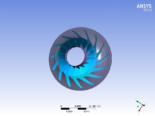
In this work, impeller is designed using cordier diagram [1], [3]. Specification of designed impeller is given in Table 1. For nu- merical analysis, impeller geometry is developed in Bladegen and design modeler, inbuilt software package in ANSYS 15 (Figure 2.1). As the domain is axisymmetric, one main blade passage has been analyzed (Figure 2.2) to save computation time.
B. Mesh
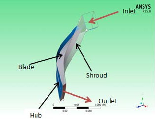
Figure 2.1: Geometry of impeller
Figure 2.2 Single passage of impeller
Table 1: Specifications of impeller
Structural analysis of the impeller blade has been done for three different materials; SS 310, INCOLOY 909 [3], Timetal 834, Ti
6-2-4-6 and their properties are given in Table 2.
For the considered impeller, structured mesh in the fluid domain has been generated in Turbogrid. Grid independence stage is achieved at 2.5 lacs passage mesh for the isentropic efficiency. This is medium sized structured mesh with 427298 nodes and
397392 elements (Figure 2.3). For boundary layer control, y+
method is chosen. The size of nearest element at hub wall is
14.1949 [11]. There is 3% clearance provided between blade
and shroud surface spanwise. For solid blade mesh is generated in mechanical model. Method used for blade mesh, is patch con- forming method which generate tetragonal mesh of total no. of nodes 34112 and no. of elements 17877. (Figure 2.4)
IJSER © 2015 http://www.ijser.org
International Journal of Scientific & Engineering Research, Volume 6, Issue 2, February-2015 598
ISSN 2229-5518
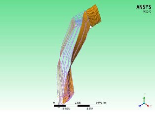
Figure 2.3: Fluid domain Mesh
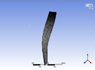
Figure 2.4: Solid blade mesh
C. Boundary conditions
In CFX setup shear stress transport (SST) is taken as turbulence model. Boundary conditions at inlet are total pressure and at outlet is mass flow rate per machine specified. At hub, shroud and blade, fluid flow is taken in no slip condition and adiabatic conditions are applied. Rotation of hub and blade is specified. Shroud is taken as counter rotating wall. At interface, mixing plane frozen rotor model is used [10]. Periodic boundaries on the sides are specified. For all properties, residual of e-4 was taken as convergence criteria.
In static structural analysis, Loads applied for the blade are: Fixed support on the hub side, Pressure and body temperatures are imported from CFX results and rotation motion given to blade. Then solutions are generated for applied loads. Due to these applied loads equivalent stress and deformation takes place.
3 RESULTS AND DISCUSSION
The structural analysis of load compressor impeller blade is carried out by CFD software ANSYS 15. The numerical analysis is carried out for different material applicable for high speed. The results for the same are evaluated for two loading conditions, First thermal loading; second combined thermal and inertial loading.
D. Thermal stresses
As fluid moves from inlet towards outlet of the blade, due to pressure and temperature loads, thermal stresses are induced inside the blade. Based on numerical analysis for thermal loading, the thermal Von Mises stresses and deformation of the impeller for different materials are represented in Table 3. Induced thermal stresses are maximum in SS 310;
1.0219E+009 Pa and minimum in Ti 6-2-4-6; 4.19E+008 Pa.
Deformation is also least in Ti 6-4-2-6 impeller blade.
Table 3: Thermal von mises stress and deformation in impeller blade
Properties | SS 310 | INCOLOY 909 | Timetal834 | Ti 6-4- 2-6 |
Ultimate strength (Pa) | 4.6E+8 | 1.44E+9 | 1.05E+9 | 1.20E+9 |
Max Von Mises Stress (Pa) | 1.0219E+9 | 5.3457E+8 | 5.38E+8 | 4.19E+8 |
Deformation (m) | 9.7487E-5 | 5.311E-5 | 7.43E-5 | 5.50E-5 |
To get better idea about thermal stresses over the blade, con- tours are plotted for different selected materials shown in figure
2.7 to 2.10.
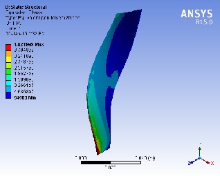
Figure 2.5 Thermal stress contours in SS 310
Thermal stress is uniform over the complete blade except in the vicinity of outlet at the hub side for all four blade materials. In the case of SS 310, at some local area near the outlet at the hub side, stresses are critical, shown in red (Figure 2.5). The cause of critical stresses in SS 310 might be high density, low
IJSER © 2015 http://www.ijser.org
International Journal of Scientific & Engineering Research, Volume 6, Issue 2, February-2015 599
ISSN 2229-5518
strength at high temperatures.
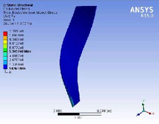
Figure 2.6 Thermal stress contours in INCOLOY 909
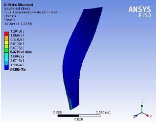

Figure 2.7 Thermal stress contour in Timetal 834
In case of INCOLOY 909, Timetal 834 , maximum induced thermal stress is in permissible limit, 5.3457E+008 Pa,
5.38E+008 Pa respectively (Figure 2.6 and 2.7) but higher than Ti 6-4-2-6 metal; 4.19E+008 Pa (Figure 2.8). Uniform distribu- tion of stresses in titanium alloys both Timetal 834 and Ti 6-4-
2-6 (figure 2.7 and 2.8) shows uniformity in thermal strength for this application
E. Structural stresses
Rotation of impeller (inertial loading) and thermal loads cause generation of structural stresses in impeller blade which are higher than the thermal stresses in case of high speed compres- sor. Numerically evaluated results using ANSYS static structur- al component for this type of loading of impeller are shown in Table 4. Maximum structural stresses are induced in SS 310;
1.9275E+009 Pa exceeding ultimate strength which is
4.6E+008 Pa. The same happens in the case of INCOLOY 909, Timetal834. Only Ti 6-4-2-6 suffice for this application in which induced structural stress; 9.91E+08 Pa is within ultimate strength limit; 1.20E+09 Pa.
Table 4: Structural stresses and deformation in impeller
Properties | SS 310 | INCOLOY 909 | Timetal834 | Ti 6-4-2-6 |
Ultimate strength (Pa) | 4.6E+8 | 1.44E+9 | 1.05E+9 | 1.20E+9 |
Max.Von Mises Stress (Pa) | 1.9275E+ 9 | 1.5977E+9 | 1.08E+9 | 9.91E+8 |
Defor- mation(m) | 4.9304E- 4 | 5.6611E-5 | 4.53E-4 | 4.57E-4 |
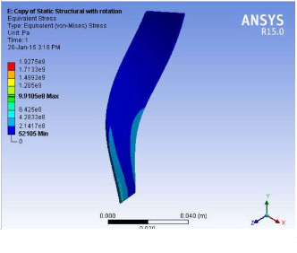
Further, contours for structural stress distribution are plotted for all materials as shown in Figure 2.9 to 2.12. The contours sug- gest that structural stresses become predominant as flow move from inlet to outlet in blade passage. Structural stresses are se- vere in the vicinity of the outlet due to high tip speed, high pressure and temperature at the hub side. Induced structural stresses are quite higher than thermal stresses for the blade made of same material.
It is observed that contours with high value of structural stress- es covered almost half of the blade i.e. from mid to outlet in meridional plane in case of SS 310 and INCOLOY 909. Whereas; in case of Timetal834 and Ti 6-4-2-6, high stress con- tours are observed only in the vicinity near the hub and shroud at the outlet. It is also clear from the contours that maximum structural stresses occurs in SS310 (Figure 2.9) and minimum in case of Ti 6-4-2-6 (Figure 2.12). The minimum and within permissible limit stresses are induced only in blade made of Ti
6-2-4-6.
Figure 2.8 Thermal stress contours in INCOLOY 909
IJSER © 2015 http://www.ijser.org
International Journal of Scientific & Engineering Research, Volume 6, Issue 2, February-2015 600
ISSN 2229-5518
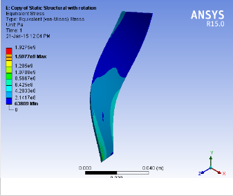
Figure 2.9 Structural Stress contour in SS 310

Figure 2.10 Structural Stress contour in INCOLOY 909

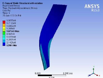
Figure 2.11 Structural Stress contour in Timetal834
Figure 2.12 Structural Stress contour in Ti 6-2-4-6
Conclusion
Auxiliary power unit is small gas turbine which comprises power section, load compressor and generator system. In the present work, stress analysis of impeller blade of the load com- pressor aircraft APU 131-9A is done using ANSYS 15. Impeller blade made of different material is numerically analyzed. Nu- merical analysis of the blade validate that critical area of ther- mal as well as structural stress is identified near to the exit, at the hub side of the blade for all four materials. From obtained results, it can be concluded that induced stresses, both thermal and structural, are within safe limit of stresses only for Ti 6-4-
2-6. Thus, best suitable material for this high speed centrifugal impeller is Ti 6-4-2-6.
References
[1] Balje O. E. ,Turbomachines, A guide to design, selection and theory, (1981), John willey & sons publication.
[2] APU 131-9[A] Auxiliary Power Unit, Advanced perfor- mance Honeywell Aerospace, Honeywell International Inc., November 2007.
[3] S.M Yahya.,“Turbines, Compressors and Fans”, Tata Mac- graw Hill, New Delhi, 2002.
[4] Meherwan P. boyce, “Centrifugal Compressors: A Basic
Guide”, PennWell Books, 2002.
[5] A Syam Prasad, BVVV Lakshmipathi Rao, A Babji, Dr P Kumar Babu, “Static and Dynamic Analysis of a Centrifugal Pump Impeller”, International Journal of Scientific & Engineer- ing Research, Volume 4, Issue 10, October-2013.
[6] V.R.S.M. Kishore Ajjarapu, K. V.P.P.Chandu, D. M. Mo- hanthy Babu, “Design and analysis of the impeller of a turbo- charger for a diesel engine”, International Journal of Advanced Engineering Research and Studies, Oct.-Dec. 2012/46-49.
[7] Dr. R. Rajappan, K. Chandrasekar, “ Structural analysis of microturbine by using CFD”, National Conference on Emerg-
IJSER © 2015 http://www.ijser.org
International Journal of Scientific & Engineering Research, Volume 6, Issue 2, February-2015 601
ISSN 2229-5518
ing Trends in Mechanical Engineering 2013.
[8] Benudhar Sahoo, Gantayat Gouda, “Failure analysis of compressor blade of typical Fighter-class Aero-engine-A Case Study”, Defence Science Journal, Vol. 52, No. 4. October 2002, pp. 363-367.
[9] Wong V. H. Guan, H & Kirke. B. (2001),” stress and dis- placement analysis of impeller blade using finite element meth- od”, The Eighth Asian –Pacific Conference on Structural Engi- neering and Construction, December 5-7 2001.
[10].M. Zangeneh, B. Nikopur, Hiroyoshi Watanabe (2010), “Development of a high performance centrifugal compressor using a 3D inverse design technique”, ImechE International conference on turbochargers and turbocharging, May 19th-20th
2010, London.
[11] R. A. Tough, A. M. Tousi, J. Gaffari, “Improving of micro- turbine’s centrifugal impeller performance by changing blade angles”. International Conference on Computational
& Experimental Engineering and Sciences, Vol. 14 no. 1, pp. 1-
22
IJSER © 2015 http://www.ijser.org