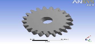
Fig. no.1: Part Design of spur gear
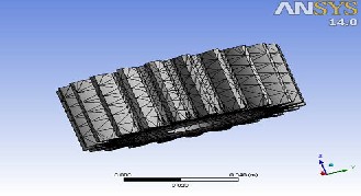
Fig. No. 2: Mess of the gear
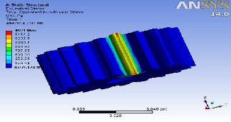
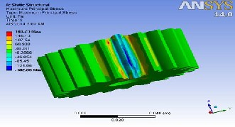
Fig. No. 3: Shear Stresses
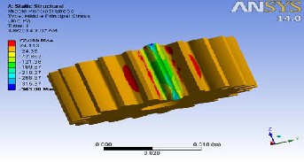
Fig. No.5: Middle Principal Stress
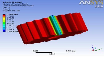
Fig. No.6: Minimum Principal Stress
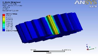
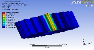
Fig. No. 7: Stress Intensity
Fig. No. 4: Directional Deformation
International Journal of Scientific & Engineering Research, Volume 5, Issue 4, April-2014 1560
ISSN 2229-5518
Pradeep Kumar Singh, Manwendra Gautam, Gangasagar, Shyam Bihari Lal
Both stress may not attain their maximum values at the same point of contact fatigue. These types of failure can be minimized by analysis of the problem during the design stage and creating proper tooth surface profile with proper manufacturing methods.
In this paper using ansys work bench software, bending stress, contact stress and static load on the tooth of spur gear drive is found.
Index Terms— Bending stress, Contact stress, Gear analysis using Ansys Work Bench, Static Load.
—————————— ——————————
Ue to globalization industries are facing competition. It be- comes more and necessary to consider alternative technol- ogy of manufacturing materials used for gears. [1]
The high volume production industry such as automobile indus- try has various manufacturing materials used gears like metal removal method, casting and forming method, but that method which is more suitable containing finishing operations optimal utilization of raw materials, short-cycle times and favorable ener- gy consumptions, compared to convectional manufacturing tech- nology. [9]
Now days, there are so many mechanisms those involve with load and requirement to understand the stress in component is increased. The mechanisms and the stress always come together and they have a strong relation between each other.[2]
Gears is a rotating cylindrical wheel having tooth cut on it and which meshes with another toothed part to transmit the pow- er or torque. Spur gear is the simplest type of gear having at tooth cut parallel to the axis of shaft on which the gear is mounted. Spur gears are used to transmit the power between parallel shafts. Spur gear give 98-99% operating efficiency.[3]
There are several kinds of stresses present in loaded and ro- tating gear teeth. We have to consider all the possibilities, so that the gears are proportional to keep all the stresses with in design limit. Generally stresses calculated in gear design formula are not necessary true stress, can make it difficult to get correct answer on gear-tooth stresses, because it may not be known whether load is uniformly distributed across the face width and whether properly shared by the two or more pairs of teeth that are in mesh at the same time. So we have to make right assumption that will allow for things like stress concentration, residual stress, misalignment and tooth error.[4]
There are two theoretical formulas, which deal with these two fatigue failure mechanism.
————————————————
• Author name - Pradeep Kumar Singh, Manwendra Gautam, B.Tech student, B.I.T, Gorakhpur,India
• Co-Author name- Gangasagar, Shyam Bihari Lal Asst. Prof. B.I.T, Go-
rakhpur,India, . E-mail: shyamfme@gmail.com
One is the Hertz equation, which can be used to calculate the bending stress.[5] .
The finite element method is capable of providing this information but it is time taken, the time need to create such a model is large. In order to reduce the modeling software can be
used. One such model is provided by ansys work bench.
The finite element method is numerical analysis technical of op- tioning approximate solution to a wide verity of engineering problems. because of its diversity and flexibility as an analysis tool , it is receiving much attention in engineering school and industries in more and more engineering situation today , we find that it is necessary to obtain approximate solution to problems rather than exact close from solution it is not possible to obtain analytical mathematical solutions are many engineering’s prob- lems. An analytical solution is a mathematical expression that gives value of the desire unknown quantity an any location in the body, as consequence it is valid for infinite number of location in the body. For problem involving complex material properties and bounder condition, the engineer resource to numerical method that provide approximate that eatable solution
First of all, we have prepared assembly in Pro/E for spur gear and save as this part as IGES for Exporting into ANSYS work- bench Environment. Import IGES mode in ANSYS workbench simulation module.
Apply material for spur gear (structural steel).
Element type solid10 node quadratic tetrahedral.
Boundary condition play the important role in finite element cal-
IJSER © 2014 http://www.ijser.org
International Journal of Scientific & Engineering Research, Volume 5, Issue 4, April-2014 1561
ISSN 2229-5518
culation here, I have taken both remote displacement for bearing supports are fixed.
Fig. no.1: Part Design of spur gear
Fig. No. 2: Mess of the gear
Fig. No. 3: Shear Stresses
Fig. No.5: Middle Principal Stress
Fig. No.6: Minimum Principal Stress
Fig. No. 7: Stress Intensity
Fig. No. 4: Directional Deformation
IJSER © 2014
Fig. no.8: Middle Principal elastic strain of the crankshaft
http://www.ijser.org
International Journal of Scientific & Engineering Research, Volume 5, Issue 4, April-2014 1562
ISSN 2229-5518
The finite element method is most widely for find a real model of the geared set using the stress analysis in the pair of gears. The development off finite element analysis model of the spur gear assembly to simulate the contact stress calculation and bending stress calculation is play more significant role in the design of gears. The study is show that Hertz theo- ry is the basis of contact stress calculation and Lewis formula is use for calculating bending stress is a pair of gear. Theoretically result obtained by Lewis formula and hertz equation and result found by comparable with finite element analysis of spur gear.
As a result, based on this finding if the contact stress minimization in the primary concern and if the large power is to be transmitted then spur gears with higher model is preferred. Hence we conclude that analysis software can be used for other analyzing purpose.
We are gratitude and valuable suggestion from director Dr.Amar singh and highly obeliesed and kindness of HOD ME (Mr. Satish kumar Diwedi) & Mr. Mahesh Kumar Singh Asst.Prof. EC De- partment of BIT, GIDA Gorakhpur for his kind supports and courage to write a paper
[1]Mrs. C.M. Meenakshi, Akash Kumar, Apoorva Priyadarshi, Digant Kumar Dash and Hare Krishna (2012) : Analysis of Spur Gear Using Finite Element Analysis, Middle-East Journal of Scien- tific Research 12 (12): 1672-1674, 2012.
[2]F. R. M. Romlay (2008): Modeling of a surface contact stress for spur gear mechanism using static and transient finite element method, Journal of Structural Durability & Health Monitoring (SDHM), Tech Science Press, Vol. 4, no.1.
[3]Vivek Karaveer, Ashish Mogrekar and T. Preman Reynold Jo- seph (2013): Modeling and Finite Element Analysis of Spur Gear, International Journal of Current Engineering and Technology ISSN 2277 – 4106.
[4]Sushil Kumar Tiwari,Upendra Kumar Joshi (2012): Stress Analysis of Mating Involute Spur Gear Teeth, International Jour- nal of Engineering Research & Technology (IJERT) Vol. 1 Issue 9, November- 2012 ISSN: 2278-0181.
[5]Mrs.Shinde S.P., Mr. Nikam A. , Mr. Mulla T.S: Static Analysis of Spur Gear Using Finite Element Analysis, IOSR Journal of Me- chanical and Civil Engineering (IOSR-JMCE) ISSN: 2278-1684, PP:
26-31.
[6]Darle W. Dudley, Practical Gear Design, McGraw-Hill Book Compa- ny, 1954 .
[7]Khurmi, Gupta R.S., 2000. “Machine design”. Khanna publication. [8]Khurmi, R.S., 1997. “Theory of machine”. Khanna publication.
[9]Rattan, S.S., 1998. “theory of machines”. Dhanpat rai publication.
[10]Machine design data book, 2003. PSG publication.
[11] Shanavas S.(2013): Stress Analysis of Composite Spur Gear, International Journal of Engineering Research & Technology (IJERT) ISSN: 2278-0181.
IJSER © 2014 http://www.ijser.org