International Journal of Scientific & Engineering Research,Volume 3, Issue 6, June-2012 1
ISSN 2229-5518
Stabilization of Networked Control System with
Packet Dropouts
SathyamBonala, BidyadharSubudhi and SandipGhosh
Abstract—Time delays in exchange of information and packet dropoutsare very common in NCS (Feedback control systems with communications networks for data exchange). Owing to the occurrence of such time delays and packet dropouts, the NCS systems are uncertain and time-varying. Also these time dealys and packet dropouts may result in degartion of the NCS performance and instability.This paper presents a new design of a state-feedback controller usingLyapunov stability criterion in terms of LMI conditions for the time varying uncertain NCS. Further, the LMI condition is used to guarantee the stability of the NCS. Results are included to demonstrate this presented approach to stabilization of NCS.
Index Terms—Communication delay, Lyapunov stability, NCS, nominal value, packet dropouts, state feedback controller,uncertainty and
Zero Order Hold (ZOH).
1 INTRODUCTION
————————————————————
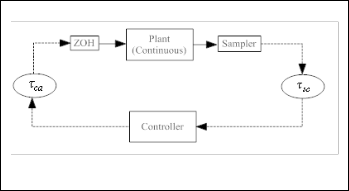
HE point-to-point architecture is the traditional communi- cation architecture for control systems [1], i.e. sensors and actuators are connected to controllers via wires. Due to ad- vances in network communications the traditional point-to- point architecture is no longer used. Instead, to meet new re- quirements, such as modularity, integrated diagnostics, quick and easy maintenance the recent industrial control schemes explit the communication networks in the feedback control systems.Further, the common-bus network architectures can improve the efficiency, flexibility and reliability of integrated applications, and reduce installation, reconfiguration, main- tenance time and costs [3,7]. In recent years, therefore, it gives rise to the so-called Network-Based Control Systems (NCSs) [2, 3] as shown in Fig.1.The challenge lies in designing NCSs are in incorporating the issues like variable time-delays and packet dropouts introduced by use of real-time communica- tion network in the system model and thereby designing the controller. Moreover, for controlling a continuous-time plant over a digital communication network (shown in Fig. 1.) offers more complexity in analysis and design. The plant is a conti- nuous one whereas the feedback control is through digital network. The overall system is remodelled in discrete-domain. The ZOH reconstructs analog singal from the discrete signals. Networks introduced in feedback control loop raises two fun- damental issues known as data packet dropouts and delay in receiving of measurement data and control data across the communication channel [8]. These issues may be approached individually or in a combination. The objective of the work
————————————————
SathyamBonala is currently pursuing Ph.D program, Centre for Industrial Electronics and Robotics, Department of Electrical Engineering, National Institute of Technology, Rourkela-769008, India.
E-mail: sathyam.bonala@mail.com
Co-Authors are with the National Institute of Technology, Rourkela, India.
described in this paper is to deal with the packet dropouts and the uncertainties arising out in the NCS due to insertion of network.Packet dropouts in NCS are always a focused prob- lem for researchers. Due to time delay and packet dropouts, there may be unavailability of measurement data at controller end or control data at actuator end. Thus, the uncertainty in the system results in instability [3].
Dropouts in a system can happen in any state, may be dro-
pouts in past state or in future state of the system. This paper describes the combined effect of the dropouts, i.e.considering the system with all possible types of dropouts as a whole and stabilizing the system. This gives a robustness to the system
Fig.1 Structure of a Networked Control System
that can tolerate any possible dropouts occurring randomly. Section 2presents the modeling of NCS with uncertainty and derives a sufficient stabilization condition using Lyapunov stability criterion. Section 3 presents results and discussions. Finally, section 4 concludes the paper.
2 SYSTEM MODEL
As in a NCS the data is being sent and received in digital form, it is necessary to go for discrete domain for easy analy-
sis. The plant dynamics in continuous form is given by
IJSER © 2012
http://www.ijser.org
International Journal of Scientific & Engineering Research,Volume 3, Issue 6, June-2012 2
ISSN 2229-5518

x(t)
Ax t Bu t
(1)
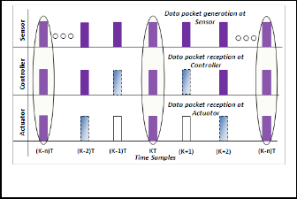
Fig.2 illustrates the transmission interval with respect to

and u t Kx t
packet loss. The dark bar at sensor end shows the data packet
where x(t )


Rn is the state vector and u(t )
Rm the plant input;
generation, the dark bar at controller and actuator shows the
A, B are known matrices and K is feedback gain to be de- signed. Continuous to discrete conversion methods [5] in- cludes finding the state transition matrix (solution of e AT ),
where A = system matrix, T = sampling interval. Computation
reception of data packets. The dashed bars show the packet is
being lost in transmission. The white bars shows packets are not received. No of sampling instances required for a complete transmission interval denotes the no of packet losses. e.g. in
of F = e AT
can be evaluated using the formula
Fig.2, at

K n T , KT and
K n T there is no packet loss, as
e AT

AT A2T 2 A3T 3
1
1! 2! 2!
(2)
the packet generated at sensor is received at actuator via con-
troller to generate another measurement data. The transmis-
and computation of G will be as,
sion interval is from

K n T to KT and from KT to

K n T .

T
G e As Bds. (e AT
0
I ) A 1B (3)
These two transmission intervals also show the amount of
packet loss as shown in Fig.2. The next objective is to find the amount of uncertainty added in system matrices due to the
A discrete system with state feedback control can be described as follows.
packet losses in the respective transmission intervals.
C o mputa tio n o f F a nd ∆F

x k 1
Fx k Gu k
(4)
For each sampling interval, T ,thereis an associated system

and u t Kx k
matrix (F) . According to (2)it can be written as-


where x(k ) Rn , u(k ) Rm are the state and input vectorin
Fn e
nAT
1 A(nT )

A2{(n)T}2
AN (nT )N
(6)
discrete domain; F, G are known matrices.When a system is used as a part of NCS there may uncertainty lies due to packet loss across the network. Due to this, the system matrix F and

G mixed with uncertainties denoted as F and G
1! 2! N !
N = maximum number of iteration at which the series tends to zero.

Nominal F value:
.Augumenting the uncertainty terms in state vector(4) can be
Let the amount of packet loss considered at
mth
sampling in-
written as
stance is m

1 , then Fm is known as the nominal F value.

x k 1
F F x k
(G G)u k (5)
Other values of F above and below of m are known as uncer-

Let F denotes the uncertainties associated with F . For each sampling interval (T) there is a F matrix assosiciated with a

tainty values. For § 0,1 , 1 we can have the generalized
formula.
system. For one sample intervalT there exits a system matrix
(m §)AT
A{(m
§)T}

A2{(m
§)T}2
AN { m
§)T }N
F e 1 ...
(7)
F1, similarly for n number of sample intervals we have m §
1! 2! N !
Fn.Transmission interval is defined as the total time required from generation of a packet at sensor side to receive that pack-
The summation of (7) for different values of § will give the F
matrix with uncertainties, which can be expressed as
et at plant side to generate a new signal via controller and ac-
F F 1
A{(m
§)T}

A2{(m
§)T}2
AN {(m
§)T}N
(8)
tuator. The relation between sampling instance, transmission
interval, and packet is shown in Fig.2.
1! 2! N !
From Eq.(8) it is seen that when § equals to zero it is the no-
minal and for other values it is uncertainty.

Fm 1 is the maxi-

mum, Fm 1 is the minimum and Fm is the nominal value of F . So (8) can be written as
A(mT )

A2{(m)T }2
F F 1 ...
1! 2!

(9)
A{(§)T }
A2{(2m§)T
§2 T 2
...
1! 2!
Fig.2. Illustration of packet loss, transmission interval in
NCS
IJSER © 2012
http://www.ijser.org
International Journal of Scientific & Engineering Research,Volume 3, Issue 6, June-2012 3
ISSN 2229-5518


where (§)T
§ , (2m§)T
1 f

§2 T 2
§ , are uncertainties and
2 f


G Dg f g Eg
§ I
§1 f ,§2 f are the maximum values of uncertainty that is asso-
ciated with the system. The generalized value of §Q can be A2 A3
1g 0
§
1g
§ A § §
I
(14)
written as-
1g 2 g 2!
3 g 3!
§ I
Ng
§Qf

{(m

§)T}Q
(mT )Q
(10) 0 §
Ng

where Q
1, 2, 3
N and the maximum values of §Q de-

For a r r matrix A and r d matrix B the size of Dg is r N ,

noted §Q . From (8),one can find the value of F as-

f f is a diagonal matrix of N N and E f
is an identity matrix

F FMAXIMUM


FNOMINAL
Str uctur a l e xplo ra tio n o f ∆F
of N d ,. Where
§ and §
are the uncertainty and maxi-

The uncertainty matrix F can be written as-


F D f f f E f
§ I
mum value of uncertainty respectively that is associated with the system. I is the identity matrix.
Considering a Lyapunovcandidate function as
A2 A3

1 f 0
1 f k k
§ A § §
1 f 2 f 2!
I
3 f 3!
§ I
0 Nf
Nf
(11)
where P is positive definite matrix, in accordance to Lyapu-
nov stability criteria [4, 6] the above equation (15) tends to
T T T

For a r r
matrix
A the size of D f
is r N ,
f f is a diagonal
V F F K G G P F F G G K P
0
(16)
matrix of

N N and E f
is an identity matrix of

N r , and §

the(16)can be written as-
is the maximum value of uncertainty that is associated with
P F F T
K T G G T P
0
the system and I
is an identity matrix.

P F F G G K P
C o mputa tio n o f G a nd ∆G

From (3),one can write G
(e AT
I ) A 1B so as the case of F
P F GK T P
f E f E f g KEg Eg K
0
(17)
T T
we can write-

2 2
P F GK P
0 f PDf Df P
1
g PDg Dg P
G (1
A nT
A nT
...
I ) A 1B
(12)

Multiply both sides by diagonal matrix ( P ) in both sides of
n 1! 2!
above equation (18),one obtaines
Nominal G value
P 1 f P E f E f P

th
g P K Eg Eg KP
P 1(F GK )T
(18)
Let the amount of packet loss considered at the m
sampling
(F GK )P 1
P 1 f D f DT
g Dg DT
instance is

m 1 then Gm is known as the nominal G value.

Assuming P 1
X and KT
Y T and using Schur compilation,
Other values of G above and below of m is known as uncer-

tainty values.

the LMI is obtained as
G e(m §) AT
A m § T
1
X XF Y G XE f
Y Eg
m § 1!
T T T T T T
T T
(13)
* X f D f D f g Dg Dg
0 0 0
(19)
A2{(m
§)T }2
AN m
N
§)T
* * f I 0
... I A 1B
2! N !
* * * g I
The summation of (13)for all values of § will give G and G
is calculated as follows-

where * is transpose of a corresponding value.

G GMAXIMUM
GNOMINAL
3 RESULTSAND DISCUSSION

The uncertainties §Qg and maximum uncertainties §Qg asso-
The transfer function
53.2718
G(s) of the DC servo motor is
ciated with G matrix can be found in the similar way asin(10).
Str uctur a l e xplo ra tio n o f ∆G
s3 9.481s2
36.18s
0.8211

and in the state space parameters

The uncertainty matrix G can be written as-
(A, B, C, D) can be obtained using MATLAB, where A=[-
IJSER © 2012
http://www.ijser.org
International Journal of Scientific & Engineering Research,Volume 3, Issue 6, June-2012 4
ISSN 2229-5518
9.4810,-36.1800,-0.8211;1,0,0;0,1,0], B=[1;0;0],C=[0,0,53.2718]
and D=0;
Considering the maximum packet loss to be 7 and finding the
and as previously assumed that, the system has maximum
packet loss 7, the maximum uncertainty values associated with F and G matrix are found to be as
system matrices F and G as per (6)and(12) for each instance of

f 23.3080, g
23.3144 respectively.

packet loss, with § 0,1, 1 , we obtain Df , Dg , E f and Eg using

(11)and (14). D f is matrix of 3 90 and E f is identity matrix of
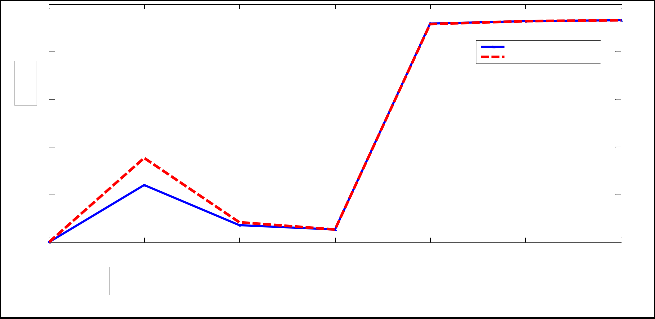
Fig.3 shows the gradual increase of system uncertainties with packet loss. Fig.4 shows that the system statesapproach to the

90 3 and

Dg is matrix of 3 30 and
Eg is identity matrix of
equliburium point irrespective to packet loss.

30 3 . After finding the all above values of we have to solve

for LMI of (19)for unknowns like X ,Y , f
25
and g . After solving
Uncertainty values of the system, with packet loss
Uncertainty value in G
20
Uncertainty value in F
15
10
5
0
1 2 3 4 5 6 7
Packet Loss
Fig. 3. Efffect of Packet droputs on Uncertainty
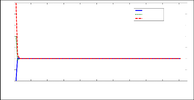
System Response to the Uncertainty due to Packet Loss
5
State Value 1
4 State Value 2
State Value 3
3
2
1
0
-1
-2
0 10 20 30 40 50 60 70 80 90 100
Time
Fig.4. System State Response .
IJSER © 2012
http://www.ijser.org
International Journal of Scientific & Engineering Research,Volume 3, Issue 6, June-2012 5
ISSN 2229-5518
4 CONCLUSIONS
Uncertainty in a NCS due to packet loss is explained in this paper considering different transmission intervals. The uncertainty analysis of the studied NCS is carried out to deal with its stabilization. A sufficient condition for stabilization is derived using LMI. A state feedback controller is also implemented to ensure the stabilization of the NCS.
ACKNOWLEDGEMENT
This work is supported by Council of Scientific and Industrial
Research (CSIR), India, under extramural research project.
REFERENCES
[1] Tipsuwan, M.-Y. Chow, “Control methodologies in networked con- trol systems”, Control Engineering Practice, Vol. 11, pp. 1099-1111,
2003.
[2] Yu Jianyong, Yu Shimin ,Wang Haiqing, “Survey on the Perfor- mance Analysis of Networked Control Systems,” in Conf. Rec.IEEE international Conference on Systems, Man and Cybernetics pp. 5068–
5073, 2004.
[3] T.C.Yang. “Networked Control System: A Brief Survey” in IEEE
proceedings control system theoryappl.vol. 153, no. 4, July 2006
[4] W. Zhang, M. S. Branicky, and S. M. Phillips. “Stability of Net- worked Control Systems” in IEEE Control Systems Magazine, vol. 21, pp. 84–99, February 2001.
[5] Katsuhiko Ogata “Discrete-Time control systems, second edi-
tion”.Prentice Hall International edition, ISBN 0-13-328642-8.
[6] Yu, Junyan , Wang, Long , Zhang, Guofeng and Yu, Mei “Output feedback stabilization of networked control systems via switched system approach”,InternationalJournal of Control, 1665 – 1677,2009
[7] R.A.Gupta and M. Y. Chow. “Networked Control System: Over-
view and Research Trends.” IEEE Trans on Industrial Electronics, vol.
57, no. 7, pp. 2527-2535, 2010.
[8] M. B. G.Cloosterman, N.V.D.Wouw, W. P. M. H. Heemels, and H.
Nijmeijer. “Stabilization of Networked Control Systems with Large Delays and Packet Dropouts.” American Control Conference, Washing- ton, USA. pp. 4991-4996, 2008.
IJSER © 2012
http://www.ijser.org