International Journal of Scientific & Engineering Research, Volume 5, Issue 12, December-2014 1384
ISSN 2229-5518
Speed Estimation of Vehicle in Intelligent Traffic Surveillance System Using Video Image Processing Asif Khan, Imran Ansari, Dr.Mohammad Shakowat Zaman Sarker and Samjhana Rayamajhi
Abstract— Intelligent System for speed estimation of vehicle in digital image sequences is one of the key technologies of Traffic Surveillance System with problems of enlarging urban scale and increasing number of vehicles. This research paper intends to develop the intelligent system for speed estimation of vehicle using image processing technique. Overall works were the software development of an intelligent system that required a video scene and user designed algorithm in MATLAB software to implement it. The Algorithm for vehicle speed detection from a video frame system consists of six major components namely, Image Acquisition, Foreground detection, Morphological operations, Vehicle detection, Speed Estimation and Result Analysis. Each algorithm consists of MATLAB codes to execute each components. The designed system is flexible and can be extended for other applications. The maximum possible error of the system was determined to be within ±3 km/h and the experiment was performed on different type of vehicles and different range of speed.
Index Terms— Traffic Surveillance, Speed Estimation, Foreground Detection, Morphological Filtering, Blob Analysis, Background
Subtraction, Gaussian Mixture Models, structuring element.
—————————— ——————————
1 INTRODUCTION
Effective and consistent traffic surveillance system is an urgent need to expand traffic control and its management. Vehicle flow estimation give the impression to be an important part in sur- veillance system. The traffic flow shows the traffic state in fixed time interval and helps to cope and control especially when there's a traffic jam and when the speed of a vehicle creates a havoc. Intelligent System for Surveillance of vehicular traffic offers a context for the extraction of significant information of traffic statistics. Automatic tracking of vehicle can be the foun- dation for many interesting applications. An accurate and effec- tual tracking capability at the heart of such a system is essential for building higher level vision-based intelligence [1].
Moreover, there is a need to create an intelligent traffic surveil- lance system with real-time moving vehicle detection, speed estimation, proficiencies. Traditionally, vehicle speed detection or surveillance was obtained using radar technology, particu- larly, radar detector and radar gun. This method still has sev- eral disadvantages such as the cosine error that happens when the direction of the radar gun is not on the direct path of the incoming vehicle. In addition, the cost of gear is one of the im- portant reasons, and also shading (radar wave reflection from two different vehicles with distinctive heights), and radio inter- ference (error caused by the existence of similar frequency of the radio waves on which a transmission is broadcasted) are two other influential factors that cause errors for speed detec-
————————————————
• Asif Khan has graduated in bachelor degree program in Electrical and Electron- ic Engineering from International Islamic University Chittagong, Bangladesh, PH-00977-9847031954. E-mail: asifali103084@gmail.com
• Imran Ansari is currently pursuing bachelor degree program in Electrical and
Electronic Engineering in International Islamic University Chittagong, Bang- ladesh, PH-0088-01840009100. E-mail: emailofimran.a@gmail.com
• Samjhana Rayamajhi has graduated in bachelor degree program in Computer Science and Engineering from International Islamic University Chittagong, Bangladesh, PH-+977-9867715407. E-mail: samjhanarayamajhi7@gmail.com
• Dr. Mohammad Shakowat Zaman Sarker is currently head of the department of
Electrical and Elctronic Engineering in International Islamic University Chit- tagong, Bangladesh. E-mail: salimsarker@gmail.com
tion and finally, the fact that radar sensor can track only one car at any time is another restriction of this method. Many works and efforts have been made in vehicle detection and speed estimation using video image processing but lacked a novel algorithm [2].
In this paper, a new algorithm is projected that takes the ad- vantage of foreground detection and morphological filtering for the speed estimation of moving vehicles in traffic. The algo- rithm requires a video input from a camera along with camera parameters such as angle & perpendicular field of view. It fur- ther requires latest edition of MATLAB software installed in a high processing speed computer.
2 SYSTEM ARCHITECTURE
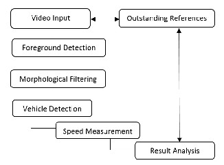
The system architecture for designing an intelligent traffic su- veillance system consists of six different components where initial work is Image acquisition where the image is acquired from a traffic surveillance video scene and then it moves algo- rithmically to other components which are discussed further.
IJSER © 2014 http://www.ijser.org
International Journal of Scientific & Engineering Research, Volume 5, Issue 12, December-2014 1385
ISSN 2229-5518
Fig. 1. System Architecture.
3 FOREGROUND DETECTION
Foreground detection is one of the foremost tasks in the field of Computer Vision whose aim is to detect changes in image sequences. A commonly used approach to extract foreground objects from the image sequence is through background sup- pression, or background subtraction and its variants.
In robust video surveillance applications, segmentation of foreground and background is a primary concern. Since the cameras are stationary in such applications, background mod- eling based foreground detection methods are widely used [3]. Such a method is composed of two main parts: modeling the background and detecting the foreground. In the first part, a background model is determined and in the second part, by comparing that background model to the current frame, the foreground objects are detected.
Here, we have used foreground detector system object found in MATLAB that uses color or grayscale video frame and compare with a background model to determine whether in- dividual pixels are part of the background or the foreground. It then computes a foreground mask. Gaussian Mixture Mod- els (GMM) concept has been used in Foreground Detector for clustering the points in video frame for background model- ling. The GMM algorithm is a good algorithm to use for the classification of static postures and non-temporal pattern recognition. Using GMM we can obtain a density estimation for each cluster.
which Gaussians may correspond to background colors. Pixel values that do not fix the background distributions are consid- ered foreground until there is a Gaussian that includes them with sufficient consistent evidence supporting it [5]. This method is very adaptable with lighting changes, repetitive motions and slow moving objects.
This method contains 2 main significant parameters –Alpha, the learning constant and T, the proportion of the data that should be accounted for by the background. The Gaussian mixture components for a pixel have normalized weights cal- culated from the past observations [5].
The parameters of the mixture components are updates with the new frames. A retrieved pixel value is compared with all the components of the mixture assigned to that pixel to find out if there is a match. A match is said to happen when the retrieved pixel value is within 2.5 times standard deviation of a mixture component. The update procedure is different for the matching component and other components. The mean values and the covariance matrices are updated for only the matching component.
In case there is not a match between the current pixel value and the mixture components related to that pixel .the compo- nent having the smallest likelihood with respect to the current pixel value is discarded. A new Gaussian component is creat- ed in place of the discarded one, having a mean value equal to the current pixel value, and a variance equal to a predeter- mined constant [6].
3.1 Algorithm for Background Substraction
In order to give a better understanding of the algorithm used for background subtraction the following steps were adopted to achieve the desired results:
1. Firstly, we compare each input pixels to the mean
'mu' of the associated components. If the value of a
pixel is close enough to a chosen component's mean,
then that component is considered as the matched
component. In order to be a matched component, the
difference between the pixels and mean must be less
than compared to the component's standard deviation
scaled by factor D in the algorithm.
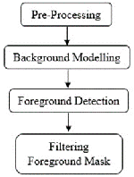
Fig. 2. Background Subtraction Flow Diagram. [4]
In this research we implement the Gaussian Mixture Model for background subtraction which is more robust than other mod- els. Most importantly it can handle multi-modal situations e.g. trees and sky which is more effectively filtered by the GMM model. Each pixel value is modelled by a mixture of Gaussian rather than a particular type of distribution. Based on the vari- ance of each of the Gaussian of the mixture, we determine
IJSER © 2014
2. Secondly, update the Gaussian weight, mean and standard deviation (variance) to reflect the new ob- tained pixel value. In relation to non-matched com- ponents the weights 'w' decreases whereas the mean and standard deviation stay the same. It is dependent upon the learning component 'p' in relation to how fast they change.
3. Thirdly, here we identify which components are parts of the background model. To do this a threshold val- ue is applied to the component weights 'w'.
4. Fourthly, in the final step we determine the fore- ground pixels. Here the pixels that are identified as
http://www.ijser.org
International Journal of Scientific & Engineering Research, Volume 5, Issue 12, December-2014 1386
ISSN 2229-5518
foreground don’t match with any components deter- mined to be the background.
4 MORPHOLOGICAL FILTERING
Binary images may contain numerous imperfections. In par- ticular, the binary regions produced by simple threshold are distorted by noise and texture. Morphological image pro- cessing pursues the goals of removing these imperfections by accounting for the form and structure of the image. Morpho- logical image processing is a collection of non-linear opera- tions related to the shape or morphology of features in an im- age. Morphological operations rely only on the relative order- ing of pixel values, not on their numerical values, and there- fore are especially suited to the processing of binary images. Morphological operations are used generally for the object structure improvement (convex hull, opening, closing, thin- ning, object marking), image preprocessing (shape simplifica- tion, ultimate erosion, noise filtering), segmentation of object and measurement of area and perimeter.
Morphological techniques probe an image with a small shape or template called a structuring element. The structuring ele- ment is positioned at all possible locations in the image and it is compared with the corresponding neighbourhood of pixels. The structuring element is a small binary image, i.e. a small matrix of pixels, each with a value of zero or one. Morphologi- cal operations apply a structuring element to an input image, creating an output image of the same size. In a morphological operation, the value of each pixel in the output image is based on a comparison of the corresponding pixel in the input image with its neighbors. By choosing the size and shape of the neighborhood, you can construct a morphological operation that is sensitive to specific shapes in the input image.
4.1 Dilation and Erosion
The most basic morphological operations are dilation and ero- sion. Dilation adds pixels to the boundaries of objects in an image, while erosion removes pixels on object boundaries. The number of pixels added or removed from the objects in an image depends on the size and shape of the structuring ele- ment used to process the image. Here, we have used structur- ing element of line shape, length 8 at 90 degree for dilation whereas structuring element of disk shape with radius 6 for erosion.
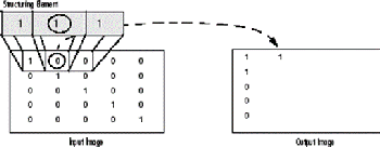
Fig. 3. Morphological Dilation of a Binary Image. [8]
We can use morphological opening to remove small objects from an image while preserving the shape and size of larger
objects in the image. The morphological close operation is a dilation followed by an erosion, using the same structuring element for both operations usually used for filling gaps in an image. In this paper, we have considered morphological filter- ing techniques for noise removal, edge detection, segmenta- tion, small objects removal, filling gaps, edge smoothening, etc. [9]
5 VEHICLE DETECTION
Vehicle detection and monitoring through video image pro- cessing is now considered as an attractive and flexible tech- nique. In this thesis we describe a novel approach by the use of foreground detection, blob analysis, morphological filtering, to detect and monitor vehicles in real-time. In this research, we have captured a video using our mobile tied with a mechani- cal arm placed at a certain elevated angle with the proper measurements. The cost of setting such a system was within our budget as a student. We took many videos of different vehicles at different speed levels and at different angle. The videos taken were processed for vehicle detection through an MATLAB algorithm.
Here, we have used Blob Analysis technique that is available in MATLAB for using the filtered image frame for the detec- tion of vehicles. Blob detection refers to mathematical methods that are aimed at detecting regions in a digital image that dif- fer in properties, such as brightness or color, compared to are- as surrounding those regions. Informally, a blob is a region of a digital image in which some properties are constant or vary within a prescribed range of values; all the points in a blob can be considered in some sense to be similar to each other [10].
In order to achieve, vehicle detection and speed estimation this proposed method tracks each blob within successive im- age frames returning output parameters like Area, Centroid and Bounding Box.
6 SPEED ESTIMATION
Speed Measurement is the main focus of this research paper. In this paper, we have used simple two point distance formula calculating the distance covered by vehicles between two frames and hence dividing it by the time between two frames obtained from the video. Although in this research we have taken only linear distance into consideration just to build up a prototype system and also due to limited resources. There is much more possibilities in this area than we are presenting and we can go far more in future with more resources.
j = (a, b) & j -1 = (c, d)
Where, the centroids location is showed in frame j and j-1 for one vehicles, with (a, b) coordinate and (c, d) coordinate.

Distance, D =�(𝑎 − 𝑐)2 (𝑏 − 𝑑)2 (1)

𝐷
Speed, S = , where t = time between 2 frames. (2)
𝑡

△ t = 2 X 1 (3)
frame rate
IJSER © 2014 http://www.ijser.org
International Journal of Scientific & Engineering Research, Volume 5, Issue 12, December-2014 1387
ISSN 2229-5518
Speed obtained here is in pixels per second. However, we need to convert this to kilometer per hour for speed standardization. For this we need to know the actual height of the image or per- pendicular field of view of the camera which helps in conver- sion of pixel to meter. So, we measured all the parameter with the help of a measuring tape and inserted those values into our algorithm and we were able to standardize the speed of the vehicles and also took many data and also we took the speed of the vehicles as per given in the speedometer.
6.1 Calculation of Perpendicular Field of View
The figure below shows the camera positioning and labelling of different parameters used for calculation of perpendicular field of view.
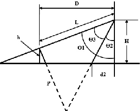
Fig. 4. Camera Positioning.
Where,
P = perpendicular field of view in the camera screen,
θ3 = the angle view covered by the camera,
H = the height of the camera,
D = the horizontal distance between the camera and vehicles,
h = the height of vehicles, and
L = real distance between camera and vehicles.
d2 = blind area
From Figure 4, we have:
P = 2L tan (θ3/2) (4)

L = �(𝐻 − ℎ)2 + 𝐷2 (5)
tical angle of view, 𝜃3 is calculated from the formula given be-
low [7]:

𝜃3 = 2 𝑎𝑟𝑐tan � 𝑣 � (8)
Where, focal length, f = F = 31mm.
Vertical dimension of 35mm image format, v = 24mm
Hence, using the equation 8, we determined the vertical angle
of view (𝜃3) as 42.32 degrees. Because the image height is 240
pixels obtained from the video and calculating the perpendicu-
lar field of view or the actual image height as 26.8 meter using
equation 6 where the height of the camera was measured 5m
from the ground, height of the vehicle was measured 1m (ap- prox.) and horizontal distance between the camera and vehicle
was measured to be 33.5m.
Comparing it to the pixel height of the image frame we got 1 pixel equals to 0.11166 meters. Thus, the average speed of the detected vehicle is calculated in meter per second which is then converted to kilometer per hour merely multiplying by 3.6.
7 RESULT AND DISCUSSION
7.1 Experimental Results
Here, we present our accomplished result step by step accord- ing to our methodology. The algorithm we prepared was ran through MATLAB and the simulation results are presented in the figures below. The filtering algorithm was changed accord- ing to the background and the objective of our detection.
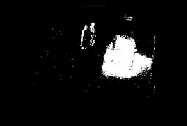
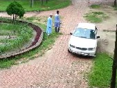
Fig.5. Video Frame no. 70. Fig.6. Foreground.


P = 2 x �(𝐻 − ℎ)2 + 𝐷2 x tan�𝜃3
(6)


2
Note that if 𝜃1 90O, then L D and we can simplify the
above equation to:


P = 2D tan�𝜃3� (7)
2
In this research, we have used Samsung galaxy SIII for captur-
ing the videos. From the derivation of angle of view formula
we can clearly conclude the vertical angle of view [15]. So, ver-
IJSER ©
http://www.ij

Fig.7. Small Objects Removed. Fig.8. Dilated Image.
International Journal of Scientific & Engineering Research, Volume 5, Issue 12, December-2014 1388
ISSN 2229-5518
Fig.9. Eroded Image. Fig.10. Edge detection.

Fig.11. Filtered and Holes filled Fig.12. Detected Vehicle
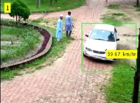
Fig.13. Speed Estimation of a Car.
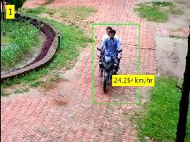
Fig.14. Speed Estimation of a Motorbike.
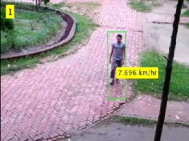
Fig.15. Speed Estimation of a Walking Man.
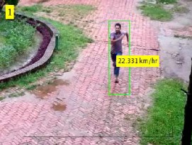
Fig.16. Speed Estimation of a Running Man.
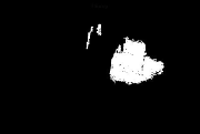
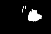
From the above figures we can clearly observe the different methodological phases of the speed estimation of vehicles. The figure 5 represents frame 70 of the video sequence which un- dergoes Foreground Detection to obtain Foreground image as shown in figure 6. Small objects with low pixel values are re- moved from detected foreground and thus results in figure 7. Then morphological operations dilation and erosion is applied to it and figure 8 & 9 are obtained. Subtracting eroded image from dilated we get the edge detected image as in figure 10. The holes inside is filled and morphological close operation is applied with disk shape structuring element of radius 2 and the resultant is again eroded with square structuring element of length 2 finally smoothening the object as shown in figure
11. Also the area that is less than 600 pixels is also removed which ensures the vehicle detection which can be asserted by the comparision of figures 10 and 11.
After Blob Analysis of the filtered image in figure 11, the vehi- cle is detected and bounded by box as shown in figure 12. The centroid obtained from first & last frame is processed for speed calculation and hence the estimated average speed is inserted onto the detected vehicle as shown in figure 13. Simi- larly, the same process is carried out for other experiment sub- jects too and speed estimation of motorbike, walking man and running man is calculated as shown in the above figures 14, 15 and 16.
7.2 Data Tables
In Table I, II & III the experimental results for speed estimation of Man, Bikes and Cars are shown and the error is calculated. The error is calculated by comparing between the detected system speed and the real speed which is obtained from a ref- erence vehicle. As shown in Tables, the error occurs because of two reasons, first, as a result of the non-linearity in grid perpendicular field of view and second, because of the shak- ing of video which induces change in filter output.
IJSER © 2014 http://www.ijser.org
International Journal of Scientific & Engineering Research, Volume 5, Issue 12, December-2014 1389
ISSN 2229-5518
can be minimized using proper filtering methods. We also took test for experimental subjects using night vision camera and infrared camera and concluded that the night conditions doesn’t affect the detection adversely as portrayed in above figures 17 &18.
TABLE 1
THE EXPERIMENTAL RESULTS FOR SPEED ESTIMATION OF MAN
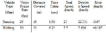
TABLE 2
THE EXPERIMENTAL RESULTS FOR SPEED ESTIMATION OF BIKES
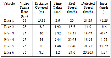
TABLE 3
THE EXPERIMENTAL RESULTS FOR SPEED ESTIMATION OF CARS
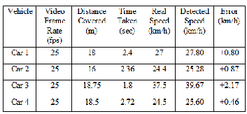
We did not mentioned all the complex calculation which is too big to be presented but rather we concluded our calculation and presented in the above table.
7.3 Evaluation
We test our system with different speed level and different background models with variation in camera angle and envi- ronmental conditions like light illumination. The effect of vari- ation in light illumination and other environmental conditions
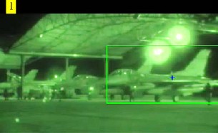
Fig.17. Detection of Aerial Vehicle Using Night Vision Camera. [13]
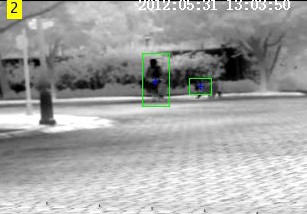
Fig.18. Detection of Human and Dog Using Infrared Camera. [14]
Our proposed speed detection system works objectively and precisely to measure different speeds but it is sensitive to fil- tering, and the filtering must be carried according to the back- ground models. After many experimentations on diverse type of vehicles and different speed range, the maximum error pos- sible of the system was determined not to exceed ±3 km/h.
7.4 Comparision
We paralleled our result with other systems like traditional radar gun, lider detector systems and other speed estimation techniques using other image processing techniques. The ra- dar gun and the modern lider detector systems have different complexity and disadvantage reagarding the speed estimation of vehiles like:
1. The person geared with radar gun or lider detector must not be in motion as it is to be held at static point.
2. High Cost of the gear.
3. Radio interference affects the radar gun system.
IJSER © 2014 http://www.ijser.org
International Journal of Scientific & Engineering Research, Volume 5, Issue 12, December-2014 1390
ISSN 2229-5518
4. Accuracy of these system is quite low [11]-[12].
There are scarce research paper that used K-means clustering, Frame differencing, Gaussian modelling with holes filling, Kalman filter and other outdated techniques for filtering but we found the algorithm we used combining different image processing techniques like foreground extraction using Gauss- ian mixture models, morphological filtering, hole filling, edge smoothening, etc. produced more effective result and could be perfected more for better results. The error that we found in our system is less than the prevailing systems for speed esti- mation. So, we can conclude this system is more efficient and economical than other technologies used for speed estimation.
Nonetheless, the error occurred can be overcomed by good camera placement and its strong calibration. Due to lack of technical and financial resources our research was limited to its bound.
8 CONCLUSION
Vehicle detection and Speed estimation is an important mis- sion in traffic surveillance system and is also supple for many other image processing related systems. However there is problem of merging of vehicles which can be minimized im- proving the filtering techniques and precising the shadow re- moval of the vehicles. And in this research only linear distance are taken into consideration overlooking non-linear distance like circular, spherical, etc. Robust development of the algo- rithm and making the system more precise and efficient shall be our future works. Further the algorithm can be enriched for number plate detection from high speed vehicles.
Finally, it can be concluded that speed estimation through video image processing is efficient and economical than con- ventional radar technology and this area is yet that to be ex- plored and take benefit from its wide possibilities. Our devel- oped algorithm is merely one of many possibilities of Intelli- gent Traffic Surveillance System and acts as a prototype for more composite and large system.
REFERENCES
[1] B. Coifman, D. Beymer, P. McLauchlan and J. Malik, “A real-time computer vision system for vehicle tracking and traffic surveillance,”Transportation Re- search Part C, vol.6, no. 4, pp. 777-782,1998.
[2] Arash Gholami Rad, Abbas Dehghani and Mohamed Rehan Karim (2010).
Vehicle speed detection in video image sequences using CVS method, Inter-
national Journal of the Physical Sciences Vol. 5(17), pp. 2555-2563.
[3] Wie Xu Yue Zhou, Yihong Gong and Hai Tao, “ Background modeling using
time dependent Markov random field with image pyramid,” in Proc. IEEE Motions’05, January 2005.
[4] Robust techniques for background subtraction in urban traffic video - Sen- Ching S. Cheung and Chandrika Kamath, Video Communications and Image Processing, SPIE Electronic Imaging, San Jose, January 2004, UCRL-JC-
153846-ABS, UCRL-CONF-200706
[5] Adaptive background mixture models for real-time tracking, Chris Stafer,
W.E.L Grimson
[6] Improved Post processing for GMM based adaptive background modelling
by Deniz Turdu, Hakan Erdogan.
[7] Ernest McCollough (1893). "Photographic Topography". Industry: A Monthly Magazine Devoted to Science, Engineering and Mechanic Arts (Industrial Publishing Company, San Francisco): 399–406.
[8] Morphological filtering, MATLAB © 1994-2013 The MathWorks, Inc.
[9] Dr. Robert Fisher (No date). Morphological Image Processing [Online].Available:https://www.cs.auckland.ac.nz/courses/compsci773s1c/ lectures/ImageProcessing-html/topic4.htm.
[10] Adnan Khashman (2008). Automatic Detection, Extraction and Recognition of
Moving Objects, Intenational Journal of Systems Applications, Engineering &
Development, Vol. 2, Issue 1. Pp. 43-51.
[11] Radar Detector, From Wikipedia, the free encyclopedia, http://
en.wikipedia.org / wiki/ Radar detector, November 2007.
[12] Lider Detector, From Wikipedia, the free encyclopedia, http://en.Wikipedia
.org/wiki/Laser_detector, November 2007.
[13] US Military Videos & Photos (2012). 169th Fighter Wing F-16s Deploy to Afghanistan - Night Vision [Online]. Available: https://www.youtube.com/watch?v=U3RY3UzmswU [2014, June 29].
[14] thermal2nightvision (2011).Clip on thermal imager, [Online]. Available:
https://www.youtube.com/watch?v=Lox156qOFDY&list=UUSmstaBfOZ
mdhVTUlPze3Kw&index=31 [2014, June 29.
[15] "Lens angle of view" by User: Moxfyre. Original uploader was Moxfyre at
en.wikipedia - Transferred from en.wikipedia; transferred to Commons by User: Moxfyre using CommonsHelper. (Original text: self-made based on: Image: Lens3.svg). Licensed under GFDL via Wikimedia Commons - http://commons.wikimedia.org/wiki/File:Lens_angle_of_view.svg#media viewer/File:Lens_angle_of_view.svg.
IJSER © 2014 http://www.ijser.org