International Journal of Scientific & Engineering Research, Volume 2, Issue 12, December-2011 1
ISSN 2229-5518
Speech Compression using DWT in FPGA
Ms. P.M.Kavathekar/Mrs.P.M.Taralkar, Prof. U.L.Bombale, Prof. P.C.Bhaskar
Abstract— The paper gives the details about the speech compression using discrete wavelet transform in FPGA. In today’s world multimedia fil es are used, storage space required for these files is more and sound files have no option so ultimate solution for this is compress ion. Compression is nothing but high input stream of data converted into smaller size. Compression is done for all, such as image, data; signals. Here speech compression technique is used and done using DWT. For this purpose only single level implementation is done to get compressed signal, and this is implemented in FPGA by using VHDL code. In this technique DWT code is written in VHDL that include separation of high level component and low level component from given input wav file and after separating these components down sampling is done and we get the compressed speech signal by keeping only approximation part of the result. The compressed speech signal was read back after up-sampling was performed. The resulting compressed signal is with some noise and future work is to reduce noise.
Index Terms—DWT, FPGA, Speech Compression, Wavelet Transform.
—————————— ——————————
1. INTRODUCTION
Ompression is process of converting an input data stream into another data stream that has smaller size. Compression provides the reduction in
redundancy also used to reduce storage requirements
overall program execution time may be reduced. This is because reduction in storage will result in reduction of disc access attempts. The compression algorithm help to reduce the bandwidth requirements and also provide a level of security for the data being transmitted.
The basic wavelet transform is time-frequency representation of a signal as it provides the time and frequency simultaneously [2]. The paper focus on emerging trend used for signal processing purpose is
‘DWT’ [Discrete wavelet transform]. DWT is used to

compress speech signal. It uses property of the wavelet as translated and scaled mother wavelets which provide multi resolution of speech signal and is used to compress the speech signal. The translation factor shifts the original signal in time domain and scale factor determines frequency and as a result, the discrete wavelet transform gives time frequency together the representation of the original signal [1].
Ms Pallavi Manohar .Kavathekar/Mrs Pallavi Meenanath Taralkar is currently pursuing master degree program in Electronics Technology in Shivaji University, Kolhapur, India,PH-09657834401,Email- pallavi.kavathekar@gmail.com., Sponsored by Bhivarabai Sawant College of Engineering and Research, Narhe,Pune..
Dr.U.L.Bombale is currently working as a Professor in Electronics Technology in Shivaji University, Kolhapur, India, PH-09049274380, Email-uttam_bombale@rediffmail.com.
Prof.P.C.Bhaskar is currently working as a M.Tech Co-Coordinator in
Electronics Technology in Shivaji University, Kolhapur, India, PH-
09881248133, Email- pxbhaskar@yahoo.co.in
The DWT consists of banks of low pass filters, high pass filters and down sampling units. Half of the filter convolution results are discarded because of the down sampling at each DWT decomposition stage. Only the approximation part of the DWT wavelet results is kept so that the number of samples is reduced by half. The level of decomposition is limited by the distortion tolerable from the resulting speech signal [1].
1.1. DIFERRENT COMPESSION TECHNIQUES
There are different compression techniques are available such as lossless compression and lossy compression techniques. Redundant information present in audio signal that is removed in lossless compression technique but it has disadvantages such as it doesn’t give the constant output data rate and very small compression ratio. And advantage is that it can be applied to any data stream to m so it is applied in the last stages of audio and video coders [2].
In lossy or predictive, the information is
irrelevant in that the intended receiver will not able to recognize that is missing. It has high compression ratio, also at reduced cost [2].
1.2. FOURIER AND WAVELET TRANSFORM
Transformations are applied to the signals to obtain information details from that signal. Fourier transform is time domain representation of signal and is not suitable if the signal has time varying frequency that is signal is not stationary. There two main difference between the short term Fourier transform and continuous wavelet transform that the Fourier transform of windowed signals are not taken and therefore single
IJSER © 2011
http://www.ijser.org
International Journal of Scientific & Engineering Research, Volume 2, Issue 12, December-2011 2
ISSN 2229-5518
peak will be seen corresponding to a sinusoidal that is
negative frequencies are not computed and the width of
the window is changed as the transform is computed for every single spectral component which is probably the most significant characteristics of the wavelet transform [2].
1.3. WAVELET TRANSFORM
The wavelet theory allows a very general and flexible
description to transform signals from time domain to a time-frequency domain, so-called time-scale domain. The representation is very useful alternative to the Window Fourier Transform, Wavelet Transform uses short window for high frequencies, leading to a good time resolution and larger windows for low frequencies leading to a good frequency resolution [3].
The DWT coefficients are usually sampled from
the Continuous Wavelet Transform as signal is passed through a half band low pass filter with impulse response h[n]. Filtering a signal corresponds to the mathematical operation of convolution the signal with the impulse response of the filter. The convolution operation in discrete time is defined as follows [2]:
x[n] * h[n] x[n] * h[n k ]
k
After passing the signal through a half band low pass filter, half of the samples can be eliminated according to Nyquist’s rule. These samples discarded without any loss of information. The low pass filtering halves the resolution, but leaves the scale unchanged [2].And is written as
y[n] h[k ] * x[2n k ]
k
2. DISCRETE WAVELET TRANSFORM
The wavelet transform provides the time – frequency information of a signal simultaneously. The Continuous Wavelet Transform is computed by changing the scale of analysis window, shifting the window in time, multiplying by the signal and integrating over all the times. But in DWT filters of different cut of frequencies are used to analyze the signal at different scales. The signal is passed through a series of high pass filters to analyze the high frequencies, and it is passed through a series of low pass filters to analyze low frequencies. Filtering a signal corresponds to mathematical operation called as convolution of the signal with impulse response of a filter.
The DWT actually computed as the signals at different frequency bands with different resolutions by
decomposing such signals into coarse approximation
and detail approximation information that is it employs
to functions scaling and wavelet function related to low pass and high pass filter respectively. The decomposition is achieved at successive high pass and low pass filtering of time domain signal.
3. DWT IMPLEMENTATION
The original signal is x[n] is passed through a half band high pass filter g[n] and a low pass filter h[n]. After the filtering, elimination of half samples takes place according to Nyquist criteria; the related level of compression can be represented as
yh ig h[k ] x[n] * g[2k n]
n
ylo w[k ] x[n] * h[2n k ]
n
Where yhigh[K] is high pass and ylow[k] is low pass filter output after sub sampling by 2. Half number of samples characterize the entire signal that is decomposition level halves the time resolution and this doubles the frequency resolution which was previously half this is 1D wavelet compression these level of decomposition can be increased. At every level, the filtering and subsampling will result in half the number of samples that is half time resolution and half the frequency band spanned that is doubles the frequency resolution. At this 1D level is sufficient to give the speech compression.
3. A. IMPLEMENTATION IN FPGA
The FPGA implementation is done in VHDL and these results are compared with the associated output generated in MATLAB’s program.
In FPGA, DWT is implemented as shown in figure1. Below the .wav file is provided as input and then as high pass coefficient and low pass coefficient expressed in program then signal is down sampled that is 1-D implementation is performed as shown in figure
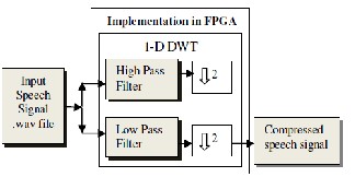
1.
Fig. 1. Implementation in FPGA
DWT implementation is done using VHDL
programming and this VHDL program of DWT is
IJSER © 2011
http://www.ijser.org
International Journal of Scientific & Engineering Research, Volume 2, Issue 12, December-2011 3
ISSN 2229-5518
downloaded using ISE11.1 and as per input .wav file is
provided as input and simulated on Modelsim the result
is compressed signal. Hardware used is Spartan 3E
board and actual compressed signal is observed.
The even and odd components of a given .wav
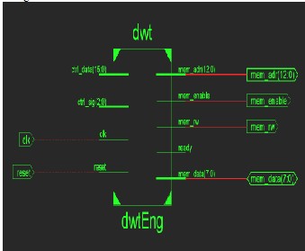
file are separate out and down sampled by 2, to get the compressed output wav file. RTL view of DWTEng is shown in figure2.
Figure 2: RTL view of DWT
RTL view consists of control and control data signal, ready and memory address, data as well as enable signals. Detail inside view of the above figure2 is shown
infig3
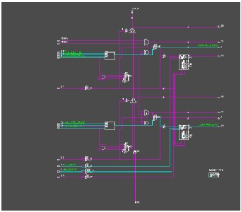
Fig.3.RTL Expanded view of DWTEng LI
The DWT is of combination of high and low
pass filter Figure3.gives the details about DWTEng low
pass filter implementation.
3. B. RESULTS OF SPEECH COMPRESSION IN FPGA
and MATLAB
Daubechies wavelet is compact orthogonal filter banks and gives the perfect reconstruction condition. Deubechies wavelet has minimum number of vanishing moments for a given signal and provides good approximation for original signal. The debauchies 4 tap (db-4) orthogonal filter bank chosen for design work [1]. For this 5 different samples of .wav file is taken and compression is done in MATLAB, the output is compared for these wav files. The table1 shows the results of signal to noise ratio, entropy elapsed time and decomposition time.
Table1
DWT RESULT OBTAINED IN MATLAB FOR
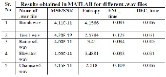
DIFFERENT .WAV FILES
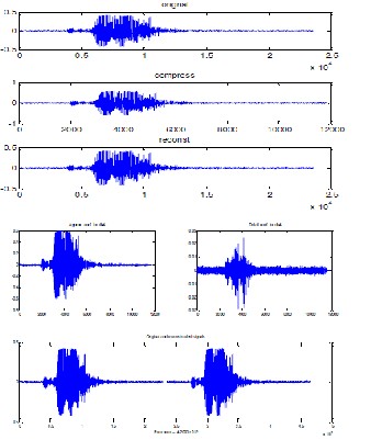
The test1.wave is given input and original signal, compressed signal output, after DWT is done and reconstructed signal with db4 approximate coefficient, also detail coefficient as well as the error coefficient is shown as in fig.3. This is performed in MATLAB and done using DWT tool function in MATLAB and gets the results.
IJSER © 2011
http://www.ijser.org
International Journal of Scientific & Engineering Research, Volume 2, Issue 12, December-2011 4
ISSN 2229-5518
optimism made this experience both rewarding and enjoyable. Most of the novel ideas and solutions found in this thesis are the result of our numerous stimulating discussions. His feedback and editorial comments were also valuable for the writing of this thesis.
I am grateful to coordinator of electronics department Prof. P. C. Bhaskar for providing the facilities for the completion of thesis.
I wish to acknowledge and thank to my family and friends, especially to my parents, sisters, brother and in-laws who always encourage me for this. My special thanks to my husband meenanath for his guidance and encouragement, without which I couldn’t have completed this work.
REFERENCE
[1] J. Pang, S.Chauhan,”FPGA Design of Speech Compression Using DWT” Proceeding of World Congress on Engineering and Computer Science October 22-24, 2008, San Franscisco, USA.
Fig.3.MATLAB Results
Simulation results of speech signal test1.wav, compression compressed signal are as shown in Figure
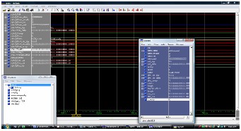
4.
Fig. 4.Simulation results using modelsim
4. CONCLUSION
The speech compression in FPGA is effective method to get the compressed speech signal and useful for increasing data storage space.
[2] Robi Polikar,”The Wavelet Tutorial PartI, Part II
and Part III”.
[3] Markus Rullmann”A new Architecture for Discrete Wavelet Transform using the Lifting Scheme”, thesis, University of NEWCASTE UPON TYNE,
Department
of Electrical and Electronics, May 2001
ACKNOWLEDGMENT
I would like to express my gratitude to all those who gave me the possibility to complete this work. This work would not have been possible without the encouragement and valuable guidance of Dr. U. L. Bombale. SUK, Kolhapur. Their enthusiasm and
IJSER © 2011
http://www.ijser.org