1poonamundre@gmail.com
2shritiwavhal.wavhal@gmail.com
3poojapatil242@gmail.com
International Journal of Scientific & Engineering Research, Volume 4, Issue 7, July-2013 79
ISSN 2229-5518
Solar Based Inverter and Charger
P.H.Patil#, Poonam Undre1, Shriti Wavhal2, Pooja Patil 3
#E&TC Department, Pune University
Indira College of Engineering and Management, Parandwadi, Pune 410 506, India
![]()
1poonamundre@gmail.com![]()
2shritiwavhal.wavhal@gmail.com![]()
3poojapatil242@gmail.com
Abstract: This system is designed for outdoor application in un-electrified remote rural areas. This system is an ideal application for house or village street lighting. The system is provided with battery storage backup sufficient to operate the light for 7-8 hours daily. The project is about to develop and fabricate the circuit that can charge the lead acid battery during day time by using solar as the source. To control the circuit for charging, we have used the circuit charging that can implement the condition of the charging whether it’s in charging condition of in float condition.The design consists of a PV array, a 12-volts lead acid battery, a control section that uses the PIC16F72 microcontroller.The control section obtains the information from the PV array through microcontroller’s Analog and Digital (A/D) ports and hence to perform the pulse width modulation (PWM) to the converter through its D/A ports. Battery’s state of charge is also controlled by the microcontroller to protect the battery from over charged. When charging condition, red LED will turn on until the battery reach the full charge state that is in floating condition and green LED will turn on. The PIC16F72 will determine whether it is daytime or night time by using sensing circuit. The light will automatically ON when the sensor circuit give the input to the PIC and PIC will give the output to the relay to switch on the light. When night change to the day, sensing circuit detect the ray from the sun, PIC will give the output to off the lamp and the charging circuit will continue charge the battery for the day.
Keywords-solar inverter, charger
A. Background
Our aim is to design and implement the Inverter and Charger system to drive a load using solar energy. Existing techniques for solar based inverter and charger systems rely typically on one of the following methods:One of the methods makes use of comparator to provide automation for inverting and
charging process. This reduces the battery life and it affects efficiency of system.
1. Another problem with existing system is, CFL lamps used as load suffers from the starting problem in winter season.
2. Existing systems does not include sufficient protection circuitry.
B. Objectives
But in our project we are using Microcontroller instead of comparators for automation purpose, which will improve accuracy and efficiency of system.To deal with starting problem of CFL lamp, we are going to use pre-heating condition.Our system is well equipped with protection circuitry such as,
1. Over voltage/ current protection.
2. Reverse voltage protection.
3. Reverse polarity protection.
C. Scope
The scope of the project includes construct the circuit in order to charge the 12V lead acid battery. The acid battery will supply power to switch the lamp when there is no light or night condition. Integration between sensor and wave sensor was also concentrated in development of this system. In order to control the circuit for switching the PIC16F72 was developed. Finally, the system will combined together to complete the development of the system.There are always remains an infinite scope of improvement to a system design. It’s only the time and financial constraints that impose a limit on the development. Following are the few enhancements that may add further value to the system.By changing transformer rating, we can drive different types of load.In the present system, solar panels used are stationary which gives less output and hence decrease the efficiency. But by making use of tracker solar panels we can increase efficiency of solar system We can use SM module to monitor system in remote areas.Fault detectors can be used.
IJSER © 2013 http://www.ijser.org
International Journal of Scientific & Engineering Research, Volume 4, Issue 7, July-2013 80
ISSN 2229-5518
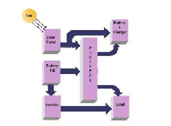
From block diagram we can see that PIC microcontroller is heart of system. Microcontroller automates whole system. Block diagram mainly includes five major blocks as follows:
1. Solar panel
2. PIC microcontroller
3. Charger
4. Inverter
5. Battery
As shown in the block diagram, solar panel converts solar energy into electrical energy. It is DC signal which is directly given to the charger circuit. Charger circuit charges battery by providing PWM pulses. Battery output is given to Inverter circuit. Inverter circuit is used to convert DC signal into AC signal. This AC signal is used for driving a load. Feedbacks of all the blocks are given to microcontroller to automate the working of the system then checks again whether the user mode switch is pressed and if it is ON once again the program converts the analogue input value to digital and saves it in the variable and the EEPROM. If the switch is OFF the program goes into automatic mode and regulates the temperature to the value set by the user. In this mode the temperature sensor detects the current temperature value and inputs it to pin of the microcontroller. The input is an analogue input and it is converted to a digital input and calibrated .Then it is displayed and checked with the user defined value by subtracting the current temperature value from the user defined temperature value saved in the EEPROM. If the result is negative it means that the current temperature value is greater than the user defined temperature value so the microcontroller makes the pin high to ON the cooler fan to bring down the temperature to the user defined value and sends SMS alerts to the user. If both the values are equal the result is zero then both pins are set to low hence fan is switched off and sends SMS alert to user mobile. The humidity level is also controlled to a predefined ideal value like temperature monitor and control system. The analogue value is converted to a digital value and saved in EEPROM. Then this value is subtracted from the ideal value and if the result is zero then pin made high and sends SMS alert to user mobile. When the result is negative again the pin is low and sends SMS alert to user mobile. Similarly for CO2 and Light sensor.
A. Experimental setup
This is the heart of the project, as we know the processor is
the heart of any project. Here PIC controller takes that job. The chip used is Atmel 16F72. There are two memory blocks in each of these PIC controllers. The program Memory and Data Memory have separate buses so that concurrent access can occur. The program memory can be read internally using Special Function Resistors in PIC. PIC 16F7X devices have a 13 bit program counter capable of addressing an 8K word x 14 bit program memory space. The PIC 16F72 devices have 8K x
14words of FLASH program memory.
Our project provides advance charging methods to improve
overall performance of battery. These methods are as follows.
IJSER © 2013 http://www.ijser.org
International Journal of Scientific & Engineering Research, Volume 4, Issue 7, July-2013 81
ISSN 2229-5518
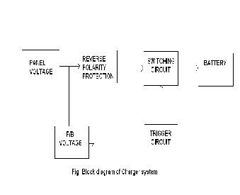
This method is used to charge battery at rapid speed. In rainy season when there is insufficient sunlight, battery
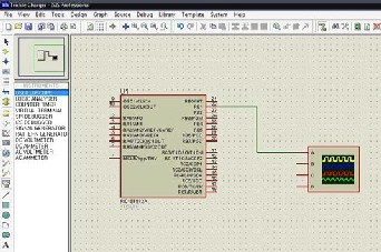
voltage is dropped at very low level due to less charging and high utilization. Boost charging provides PWM charging pulses having large ON period.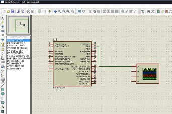 Fig.b2:Proteus stimulation diagram of trickle charging
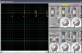
Fig.a1:Proteus stimulation diagram of boost charging 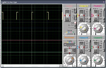
Fig.b2: Waveform of trickle charging on CRO
Preheating is most important type condition.This condition has used in winter season basically.In these we are using polyster capacitor.operation frequency is 42Mhz. In boost charging used when battery voltage is less than 13V.It is used in inverter section.This is great advantage of preheating.Preheating helps for turn ON CFL lamp very easily.
Fig.a2:Waveform of boost charging on CRO
Trickle charging:
This method is used to charge the battery in slow and
steady rate.This method is provided when battery voltage is near about maximum voltage. It provides PWM charging pulses having large OFF period.
IJSER © 2013 http://www.ijser.org
International Journal of Scientific & Engineering Research, Volume 4, Issue 7, July-2013 82
ISSN 2229-5518
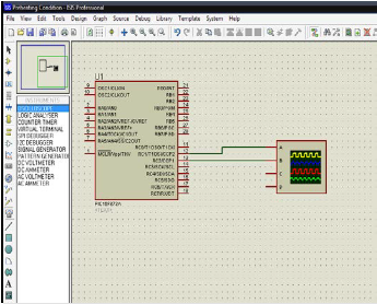
Fig.c1:Proteus stimulation diagram for inverter
Software is developed in embedded C language. proteus software is used for programming and controlling Initialize LCD
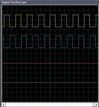
Fig.c2: inverter input signals waveform
existing technology in the field of wireless communication and with the wide improvement of GSM technology which can improve Short Message Service with the help of embedded technology anything may become possible and easy.
Each and every project is never complete as new things are learned further modifications can be done. Thus we have tried to make an automated solar tracking system which will increase the efficiency of the solar panel system available Although there is higher initial cost involved we have tried to make the system cost effective .This is just the beginning, we can add different enhancements to make the system more the efficient so that it will work round the year. The solar panels using this system compared with the system prevalent at present has many advantages. In the present system, solar panels used are stationary which gives less output and hence decrease the efficiency. But by making use of tracker solar panels we can increase efficiency of solar system. The operator interference is minimal since the system is automated this increases efficiency of the stationary solar system. The GSM facility provided by the system helps the user to monitor the system from anywhere in the world. There is a lot of hard work involved in developing such a project. Through years of experience the project will get better. Each project will get better than previous one as practice can make us perfect.
1. “An Intelligent DC-DC/AC Converter.” [Online].http://www.ee.nmt.edu/erives/382
10/Intelligent%20Converter.pdf [Accesed: Feb 10,2010]
2. “Intelligent Power Conversion Functions and Benefits.” [Online].
3. “What is a Smart Battery Charger.” [Online].http://www.wisegeek.com/what-is-a-smart- battery-charger.htm [Accesed: Apr 11, 2010].
4. “What is a Smart Battery.” [Online].http://www.wisegeek.com/what-is-a-smart- battery.htm [Accesed: Apr 11, 2010].
5. “Smart Battery Charger Specification.” [Online].http://sbs-forum.org/specs/sbc110.pdf
[Accesed: Apr 11, 2010
The system which we are discussed above is implemented on the board and results are shown. But the system can work more efficiently with present technology and may improve the
IJSER © 2013 http://www.ijser.org