International Journal of Scientific & Engineering Research, Volume 4, Issue 10, October-2013 111
ISSN 2229-5518
Smart walking stick - an electronic approach to assist visually disabled persons
Mohammad Hazzaz Mahmud, Rana Saha, Sayemul Islam
Abstract— from the very beginning of human history, peoples are suffering from many disabilities. Among those, blindness is very common and unendurable. Science and technology always try to make human life easier. So the main purpose of this paper is based on abating the disabilities of blindness by constructing a microcontroller based automated hardware that can corroborate a blind to detect obstacles in front of him/her instantly. The hardware consists of a microcontroller incorporated with ping sonar sensor, proximity sensor, wet detector, a micro pager motor and additional equipment.
Index Terms— a Ping Sonar Sensor from Parallax, a GH311 Ultrasonic Obstacle Sensor, PIC16F690 Microcontroller (High performance 8-bit CMOS MCU), Micro Pager Motor, Proteus, Micro-C for PIC.
1 INTRODUCTION
—————————— ——————————
position of the stick. Positioning of the sensors is
predefined by real life application. The entire project is
designed using micro-controller based upon its reliability.
lindness is a very common disability among the peoples throughout the world. According to the World Health Organization (WHO) 285 million
people are visually impaired worldwide, 39 million are blind and 246 have low vision. About 90% of the world’s visually impaired live in developing countries [1]. Looking at this locally, we see that within Australia, it is estimated that there are 380 thousand people who have low vision or are classed as legally blind. A person who cannot see at 6 meter nor has a field vision of 10° or less is considered legally blind. 95% of people classed as legally blind have some vision. To be classed as blind, there is a total loss of vision. Low vision cannot be corrected by visual aids such as glasses and contacts [2]. For the indigents blindness is a curse. They need help to walk outside and all other daily essential works. So the paper glows a system that tries to remove the curse of blindness and make them self- dependent to do their daily chores. It is a walking stick, normally used by the blinds. But it is fully automated, easy to maintain, cheap and it is very comfortable to use [3]. The power consumption is low and can be operated easily. Above all the stick is very economic over the conventional one.
The walking stick mentioned above is a stick that consists of a circuit board that contains a PIC micro controller, a LED for indication, input from micro-pager motor, inputs from sensors that are installed at proper
The micro-controller is code protected so its security bridge cannot be override except the vendor or owner. Here one micro-controller is used, that is PIC16F690. All sensors’ data are taken by the micro-controller and it produces different Pulse Width Modulation (PWM) based on the sensors output to operate pager motor.
2 METHODOLOGIES
As it has been noted earlier the implanted smart walking stick scheme corresponds of several subsystems. These subsystems fundamentally sensor based. The integral scheme is designed with a circuitry fundament on a PIC microcontroller (PIC16F90). This microcontroller operates
————————————————
• Mohammad Hazzaz Mahmud has completed Bachelor degree program in
Electrical and Electronic Engineering, Dhaka, Bangladesh. Email: hazzaz.aust@outlook.com
• Rana Saha has completed Bachelor degree program in Electrical and
Electronic Engineering, Dhaka, Bangladesh.
Email: rana_saha_bd@live.com
• Sayemul Islam has completed Bachelor degree program in Electrical and
Electronic Engineering, Dhaka, Bangladesh.
Email: sayem707@gmail.com
the whole scheme by functioning and linking the subsystems in good order.
IJSER © 2013 http://www.ijser.org
International Journal of Scientific & Engineering Research, Volume 4, Issue 10, October-2013 112
ISSN 2229-5518
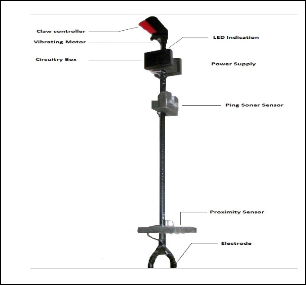
Figure 1 shows Physical Structure of Smart stick
The sensor based circuitry consisting of sensors Ping Sonar
Sensor is used to detect ranges from obstacles, GH311
Ultrasonic Obstacle Sensor is applied to notice what's at the
bottom of the stick i.e. the terrain [4], a pair of electrodes are used to observe wetness at its underneath.
A PIC16F690 microcontroller reads these sensors and drives a buzzer, a LED and a motor with PWM. Vibratory module comprise with a Micro Pager Motor which outputs is assured by PWM to obtain different vibratory pattern. An audio output is designated by a buzzer alarm. The output signals are operated by PWM to hold distinct sound form as well as it indicates the scheme’s status.
The output indications provided by the microcontroller are distinctive as per sensor. Based on the strength of vibration of the motor or the beeping of the buzzer or the blinking of the LED embedded with the stick a disabled person may determine if he/she is walking towards a manhole or an edge or a large opening at nearby bottom or something similar. At the same time he/she may get the sense of his/her distance from nearby objects and if he/she is walking in a wet or muddy or potentially slippery terrain.
The microcontroller and power circuitry (preferably battery based) are the crucial part of the scheme. The simplicity of the design makes it easy to use by any person and at the same time the cost of manufacturing such sticks is kept low.
3 GENERAL DESCRIPTION OF EQUIPMENTS
3.1 General Description for Microcontroller Microcontroller is a device that can be programmed for various purposes. For our smart walking stick we have
used PIC series microcontroller (PIC16F690). It is a 20-Pin
Flash-Based, 8-Bit CMOS Microcontroller with Nano Watt
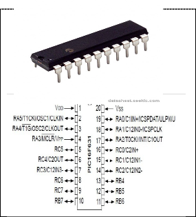
Technology. Here Pin RB5 used for wet detection by two
electrodes, Pin RB6 used for reading proximity signal and Pin RB7 used for reading data from PING sonar sensor. Pin RC5 is configured for PWM output, RB4 and RC0 are configured for Buzzer and LED output respectively. We have used its internal microcontroller as 4MHz. There are as many as eighteen general purpose I/O pins available. So it has three ports available which are PORTA, PORTB, and PORTC. [3] To program this PIC microcontroller an external programmer/loader is needed. PIC16F690 is shown in figure 2.
3.2 General Description for Ping Sonar Sensor
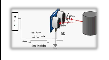
The Parallax PING ultrasonic distance sensor provides
Figure: 3
precise, non-contact distance measurements from about 2 cm (0.8 inches) to 3 meters (3.3 yards). It is very easy to connect to microcontrollers requiring only one I/O pin [4].
Figure 3 shows Ping Sonar Sensor
In smart walking stick scheme it is used to detect ranges from obstacles. The PING sensor works by transmitting an ultrasonic (well above human hearing range) burst and providing an output pulse that corresponds to the time required for the burst echo to return to the sensor. By measuring the echo pulse width, the distance to target can easily be calculated.
3.3 General Description for GH-311 Ultrasonic
Obstacle
The GH-311 ultrasonic sensor provides precise, non-contact distance measurements from about 2 cm (0.8 inches) to 3 meters (3.3 yards) [5].In smart walking stick system it is
used to map what's at the bottom of the stick.
IJSER © 2013 http://www.ijser.org
International Journal of Scientific & Engineering Research, Volume 4, Issue 10, October-2013 113
ISSN 2229-5518
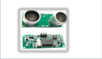
Figure: 4
Figure 4 shows GH-311 ultrasonic obstacle sensor.
The GH-311 sensor detects objects by emitting a short
ultrasonic burst and then listening" for the echo. Under control of a host microcontroller (trigger pulse), the sensor emits a short 40 kHz (ultrasonic) burst. This burst travels through the air, hits an object and then bounces back to the
sensor. The GH-311 sensor provides an output pulse to the host that will terminate when the echo is detected; hence the width of this pulse corresponds to the distance to the target. Figure 3 shows a GH-311 ultrasonic sensor module.
3.4 General Description for Vibrating Motor
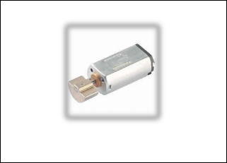
The smart walking stick scheme has an additional vibratory feedback mechanism which is crucial for multiple disable peoples i.e. sensory disability associated with a motor disability or intellectual disability. This enhances the overall feedback received by the user who receives the output in different formats of vibration; distinctive as per sensors.
Figure: 5
Figure 5 shows a Vibrating Motor.
4 FEATURES OF SMART WALKING STICK SYSTEM
1. Smartest than the other mainstream white canes.
2. Entirely automated.
3. Can be maintained & operated easily.
4. Very comfy to function.
5. Authentic & Durable.
6. Low power consumption.
7. The Microcontroller can be code protected.
8. Simplicity of the design makes it effective
navigation assistant [6].
9. Obstacle & hole can be determined easily by
sensors readings.
10. Wet or muddy or potentially slippery terrain can
be detected by a pair of electrodes.
11. Vibratory signal is crucial for multiple disable
persons to get exact information from the output.
12. Apart from others blind guidance systems; it has a
claw controller; which provides mechanical
advantage beyond anyone’s imagination [7].
13. Additional features like digital compass, GPS,
voice guidance can be incorporated [10, 11].
14. Special lineament like extra secondary IR/laser
sensor package, remote monitoring package,
weather monitoring package and other hardware
can also be integrated [12].
15. Overall manufacturing cost is low & parts are
available in both local & international market.
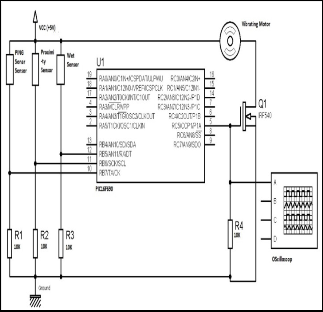
5 CIRCUIT DIAGRAM
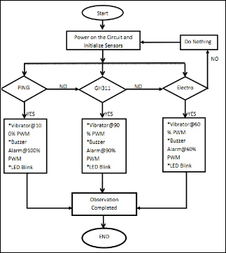
6 FLOW CHART
IJSER © 2013 http://www.ijser.org
International Journal of Scientific & Engineering Research, Volume 4, Issue 10, October-2013 114
ISSN 2229-5518
7 CONCLUSION
The paper intended the blueprint and architecture of a smarter concept of SMART WALKING STICK for blind and disable people. This blind aid system can be rendered a fresh dimension of useful assistance and gives a sense of artificial vision along with dedicated obstacle and hollow detection circuitry. This cost effective and light weight device can be designed to take of pattern of a clastic and portable device, which can be unconditionally mounted on an ordinary white cane or blind stick. The aimed combination of several working sub-systems makes a time demanding system that monitors the environmental scenario of static and dynamic objects and provides necessary feedback forming navigation more precise, safe and secure.
7 REFERENCES
[1] http://www.who.int/mediacentre/factsheets/fs2
82/en/
[2] Australian bureau of statistics, Blindness
complete/partial,2003http://www.abs.gov.au/au
sstats/abs@.nsf/0/5796EA76D51A2403CA256D3A
002C7153?Open&Highlight=0.
[3] Johann Borenstein and Yoram Koren, The Guide
Cane –A computerized Travel aid for the Active Guidance for the Blind Pedestrians, proceedings of the IEEE international conference on Robotics and
IJSER © 2013 http://www.ijser.org
Automation, Albuquerque, 1997, page 1283-1288, April 21-27.
[4] C. Gearhart, A. Herold, B. Self, C. Birdsong, L.
Slivovsky, Use of ultrasonic sensors in the development
of an Electronic Travel Aid, Sensors Applications
Symposium, 2009, SAS 2009, IEEE, pp.275-280, 17-
19 Feb
[5] http://www.microchip.com/wwwproducts/Devi
ces.aspx?dDocName=en023112
[6] http://www.parallax.com/Portals/0/Downloads
/docs/prod/acc/28015-PING-v1.6.pdf
[7] http://www.united77.com/Ultra.html
[8] Shang Wenqin; Jiang Wei; Chu Jian; A machine
vision based navigation system for the blind
China Computer Science and Automation
Engineering (CSAE), 2011 IEEE International
Conference on 10-12 June 2011
[9] Hashino, S.; Ghurchian, R.; A blind guidance system for
street crossings based on ultrasonic sensors. Information and Automation (ICIA), 2010 IEEE International Conference on June 2010
[10] F. Gaunet and X. Briffault, “Exploring the functional specifications of a localized way finding verbal aid for blind pedestrians: simple and structured urban areas," Human Computer Interaction, vol. 20, no. 3, pp. 267-
314, 2005.
[11] J. M. Loomis, J. R. Marston, R. G. Golledge, and R. L.
Klatzky, “Personal guidance system for people with visual impairment: A comparison of spatial displays for
route guidance," Journal of Visual Impairment and
Blindness, no. 99, pp. 219-232, 2005.
[12] J. M. Benjamine, N. A Ali and A. F. Schepis, a laser
cane for the blind, proceeding of the San Diego
Biomedical Symposium, 1973, Vol. 12, pp 53-57.