International Journal of Scientific & Engineering Research, Volume ś, Issue 1, ¢-201Ś 10
ISSN 2229-5518
Simulation of the Interaction of Solitary Waves and Breakwaters Using Smoothed Particle Hydrodynamics
First Author, Second Author, Third Author
Abstract— Designing safe and economical seashore structures such as breakwaters is of great importance in the engineering of seashore structures. Besides, breakwaters have a wide variety of applications in commercial and recreational harbors, military activities and offs hore operations. In the de- signing process of aforementioned structures, wave rose and wave transmission coefficient are important criteria in determining the height of these structures. Smoothed particle hydrodynamics method is also a powerful tool for studying the free-surface and simulation of waves and structures inter- action. Hence, in the present study, the performance of submerged breakwaters against solitary waves was examined. The main objective of this study was to investigate transmission coefficient of solitary waves in fixed submerged breakwaters. To study the standing waves formed in front of a trapezoid submerged breakwater, a two-dimensional numerical model, without Lagrangian mesh approach and using smoothed particle hydrodynamics method was developed. In this numerical model, solving Navier-Stokes equations are used to investigate the problem. The waves are generated using a piston- type wavemaker which is moving forward. At first, the results of the numerical model were compared to the results of experimental model, and the accu- racy of the model was evaluated. Then the transmission coefficient of solitary waves over the submerged breakwater was studied in different scenarios.
Index Terms— Submerged Breakwaters, Solitary Waves, Smoothed Particle Hydrodynamics
IJ————S—————— E———————R———
rotecting the coasts against the waves in countries with long coastlines, like Iran, is considered as a serious issue. Also, due to the growth and development of seaports, promenades and coastal installations, using breakwaters for improving water quality is an essential issue. To this end, a variety of coastal structures were built and utilized along the coasts. Submerged breakwater is one of these structures. Sim- ple structure, cost effectiveness, safety for maritime transport vessels, short construction period, retaining the coastal beau- ties for tourism attraction, preventing beach erosion by dis- persing the incoming waves and the high solidity of these structures are among the advantages that can be enumerated for this type of breakwaters. Geometry, the material properties used in the breakwater and environmental features, are among the relevant factors that increase the efficiency of sub- merged breakwaters. In this paper, using the SPH method, the profile of a transmitted wave through a trapezoidal breakwa- ter has been investigated. Following, a number of studies which have been carried out on submerged breakwater are presented. Masanori, et al. (1992) has studied the characteris- tics of solitary wave breaking caused by a submerged obstacle. In this study, the wave breaking rate was calculated using regression method of wave breaking. Norio Hayakawa, et al. (1998), have studied the wave fields around submerged breakwaters using 2-dimentional and 3-dimentional models and compared the results of the empirical method with the results of the theoretical method. Wan Decheng and Wu Guoxiong (1998) have studied solitary wave interaction with a multi bodies breakwater consisted of two rectangular cylin- ders, empirically and theoretically. Akinori Yoshida, et al.
(2002) compared the wave field behind a trapezoid submerged breakwater and two trapezoid submerged breakwaters. Ha- keem K. Johnson, et al. (2005) have investigated waves and currents around a trapezoid breakwater empirically and theo- retically. Hong-Bin Chen, et al. (2007) studied wave transfor- mation between trapezoid submerged breakwater and seawall with different profiles empirically. Hasanat Zaman, et al. (2008) investigated the deformation of the monochromatic water wave propagating over a submerged parabolic break- water and the extent of returning wave field in presence of uniform current. Yong-gang Cao, et al. (2010) have carried out a numerical investigation of the hydrodynamic characteristics of water waves propagating around two trapezoid submerged breakwaters.
Different methods have been suggested for SPH simulation of waves. Song Dong (2010) has presented the ISPH interaction method with porous environment for water wave simulation. Changen et al. (2011) suggested an optimum SPH method for
3-dimensional wave simulation.
Smoothed particle hydrodynamic is based on integral interpo- lation. The primary rule is that every function can be approx- imated using the following equation:
![]() (1)
(1)
in which r is position vector of influence point, w is the
IJSER © 201
11
International Journal of Scientific & Engineering Research Volume śǰȱ ȱŗǰȱ ¢ȬŘŖŗŚȱȱȱȱȱȱ
ISSN 2229-5518
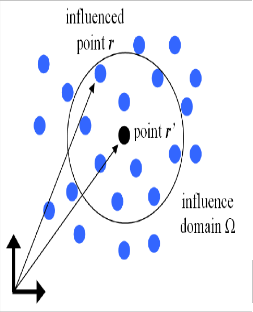
weighting or kernel function and h is the smoothing length that adjust the support domain (influence domain) (Figure 1).

ent types of smoothing functions, cubic spline smoothing function (Equation 4) has been used in this study.
(4)
In this equation, in 3-dimentional simulation is .
The basic equations governing fluid dynamics are based on three main physical laws of mass, momentum, energy conser- vation and the motion equations of smoothed particle hydro- dynamics are obtained based on the Lagrangian formulation these three laws.
2.2 Momentum Equation
The momentum conservation equation in a continuous do- main is as follows:
Fig 1. The influence domain of hydrodynamic particles
(5)
velocity, pressure and is density. ![]() accel- eration of gravity and is also shows the dispersion equation
accel- eration of gravity and is also shows the dispersion equation
IJSEand the three typRes of this equation can be stated as follows:
It is evident that the value of h should be more that the initial
distance between the particles. If equation (1) can be written in discrete form, then the approximation equation for particle a will be as follows:
(2)
in which, mb, mass, ρb , density and is the weighting or kernel function. One the advantage of weighting function (kernel function) in the smoothed particle hydrodynamics method is that the derivative of weight func- tion can be computed analytically. While, in finite difference method, the derivative is estimated by using the neighboring points and their distance. In case the points are equidistant, the calculation would be difficult. However, the derivative of equation (2) is as follows:
![]() (3)
(3)
2.1. The smoothing function
The performance of smoothed particle hydrodynamics model depends on choice of weight function (kernel). This choice should satisfy the following conditions:
1. Being positive 2. Support Field 3. Being Normalized 4.
Having Delta function behavior 5. Having steady decrease with displacement
The kernel function is dependent on the length of smoother and the nondimensional distance between the particles ![]() , in which r is the distance between particles a and b. The h pa- rameter is controlling the size the field around particle a for influencing on its neighboring particles. From among differ-
, in which r is the distance between particles a and b. The h pa- rameter is controlling the size the field around particle a for influencing on its neighboring particles. From among differ-
1. Artificial Viscosity
2. Layered viscosity
3. Turbulence model (artificial viscosity + SPS)
For the purpose of the present study artificial viscosity was
used.
Artificial Viscosity
This statement was introduced by Monaghan and it was uti- lized because of its simplicity in smoothed particle hydrody- namics formulation. Thus, equation (4) can be written in dis- crete form as follows: ![]() (6)
(6)

in which, the pressure gradient were written as follows:
(7)

At the same time, the viscosity equation is defined as fol- lows:
![]() (8)
(8)
![]()
in which the values of and are:
(9)
(10)
IJSER © 201
12
International Journal of Scientific & Engineering Research Volume śǰȱ ȱŗǰȱ ¢ȬŘŖŗŚȱȱȱȱȱȱ
ISSN 2229-5518
![]() is a parameter which can change according to every particular problem. In the present study, the values of 0.12 and 0.08 were used for
is a parameter which can change according to every particular problem. In the present study, the values of 0.12 and 0.08 were used for ![]() and the results were compared.
and the results were compared.
7.2 Time step
In this study, for the purpose of time discretization, the two dif- ferent algorithms of Verlet and predictor-corrector were used with different formulations.
1) Predictor-Corrector Algorithm
This algorithm predicts the changes during a time frame in the following form:
numerical tank was 0.3m (d=0.3m) (Figure 2). The motion of wave pedal for the ratio of wave height to water depth in different scenarios is presented in Table 1.
TABLE 1. THE CHARACTERISTICS OF GENERATED SOLITARY WAVES![]()
Different
7 6 5 4 3 2 1
![]()
![]()
scenarios
0.7 | 0.6 | 0.5 | 0.4 | 0.3 | 0.2 | 0.1 | H/d |
0.21 | 0.18 | 0.15 | 0.12 | 0.09 | 0.06 | 0.03 | H |
0.3 0.3 0.3 0.3 0.3 0.3 0.3 d
2.60 2.80 3.07 3.41 3.97 4.86 6.828
(11)
The value of is calculated based of equation of state. These values will be modified using force values in the mid- dle time step
 (12)
(12)
Finally, the values at the end of time step were calculated as fol-
lows:
(13)
Also, the pressure values were estimated using density values and![]() .
.
1) Verlet algorithm
![]()
In order to discretize the momentum equation, the Verlet algo- rithm is divided into two parts. Generally, the variables are calcu- lated as follows:
(14)
Also, in each time step, the variables will be calculated as follows:
![]() (15)
(15)
The above equation is presented to avoid the divergence in the solution process, as the equations will be out of synthetic state, over time.
3.1 Generation of solitary waves and the examination
of transmission coefficient of solitary waves over
them
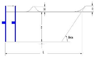
In the early simulations, according to Maiti's simulations, at first, the length of the flat part of numerical tank was considered to be
9.7m and 0.3m of the remaining length of the tank was drawn
with a 45-degree angle (L=10m). The depth of slack water in the
Fig 2. Dimensions of computational geometry
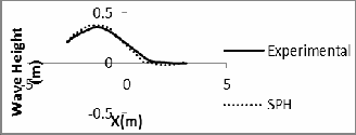
The results of these simulations, in which smoothed particle hy- drodynamics method was used are compared with the results of Sangita's simulations and illustrated in the following figures. As it can be seen in Figure 3, the height of solitary wave is 0.03m. The modellings conducted during the seconds 0 to 3 and also 9 to 10, have a very high consistency. Also the wave crest in the 6th se- cond is completely consistant with Sangita's model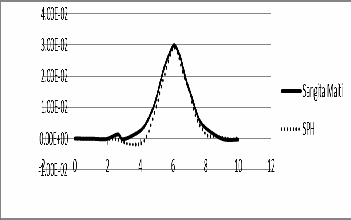
Figure 3. Comparing the calculated solitary wave at H/d=0.1 with numeri- cal results of Sangita.
The depth of water in the simulated tank is 0.3m and the height of solitary wave is 0.06m. The difference between these two simula- tions is 5 percent. Compared to Sangita's work, there is 2.5 per- cent computational error for wave crest.
IJSER © 201
International Journal of Scientific & Engineering Research Volume śǰȱ ȱŗǰȱ ¢ȬŘŖŗŚȱȱȱȱȱȱ
ISSN 2229-5518
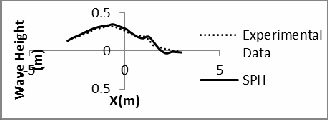
In order to verify the interaction scheme of wave with breakwa- ter, the results of simulations, using smoothed particles hydrody- namics method and experimental method have been compared. Grili et al. studied the changes of solitary waves characteristics breaking over submerged breakwater. The dimensions of wave flume, generated wave as well as the characteristics of the sup- posed breakwater are shown in Table 2.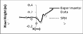
13
(d)
TABLE 2.CHARACTERISTICS OF WAVE, WAVE FLUME AND BREAKWA- TER
![]()
![]()

![]()
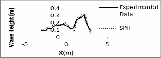
Fig 4. Comparing the simulated free-surface using smoothed particles
hydrodynamics method and experimental method
TABLE 3 SHOWS THE TIME OF EACH FIGURE AND THE ERROR AVER- AGE VALUE.
TABLE 3. THE VALUES OF COMPUTATIONAL ERROR
![]()
![]()
![]()
![]()
IJSEAs it can be seenRin the above table, the results of simulation, us-
The results of simulation are shown in Figures 4-a to 4-d.
(a)
ing smoothed particles hydrodynamics method, comparing to numerical results, have an acceptable accuracy.
3.2.2 Examining the distance between two breakwaters
In this section, the impact of the distance between two breakwa- ters is examined. The distances are selected in a way that starts form values less that wavelength and ends with values more than wavelength. The height of the supposed wave was H=0.3. Also, the water depth was 1.2m. The length of wave flume was 70m and the breakwater was located on the left-hand with distance of
30m. The other properties of breakwater dimensions are pre- sented in Table 4.![]()
Table 4. The characteristics of breakwater
![]()
(b)
(c)
![]()
![]()
IJSER © 201
14
International Journal of Scientific & Engineering Research Volume śǰȱ ȱŗǰȱ ¢ȬŘŖŗŚȱȱȱȱȱȱ
ISSN 2229-5518
In Figure 5, the impact of the distance between two breakwaters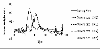
is shown.
Fig 5. The simulated free-surface for different distances between two breakwaters
As it can be seen in Figure 5, right at the moment that the wave reaches the first breakwater, the wave height has reached 0.25m and after passing over the second breakwater, reaches different heights. If we define the height of incoming wave as H and the height of outgoing wave as H', the impact coefficient of breakwa- ters can be definition as ![]() so that 1 is indicating the zero influence of the breakwater and values greater than 1 are indicat- ing greater influence of the breakwater. The α values calculated
so that 1 is indicating the zero influence of the breakwater and values greater than 1 are indicat- ing greater influence of the breakwater. The α values calculated
3.3.3. Examining the breakwater slope
In this section, the impact of breakwater slope on damping coeffi- cient ![]() was examined. It was supposed that the breakwater was in previous position and also the solitary wave have the characteristics of the wave in the previous state. The side slope of breakwater was studied which is located in its back side (on the right). The breakwater properties and supposed slopes are pre- sented in Table 5.
was examined. It was supposed that the breakwater was in previous position and also the solitary wave have the characteristics of the wave in the previous state. The side slope of breakwater was studied which is located in its back side (on the right). The breakwater properties and supposed slopes are pre- sented in Table 5.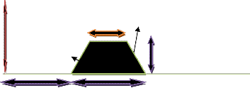
![]()
d
![]()
Figure 7. The computational domain of supposed problem
for different distances are preIsented Jin Table 5. SER
![]()
TABLE 5. EXAMINING THE EFFECT OF THE DISTANCE BETWEEN TWO
TABLE 6. THE CHARACTERISTICS OF SUPPOSED BREAKWATER
BREAKWATERS

1.247285 1.42718 1.3381 1.337985
As it can be seen, the reduction of wave height at X=0.3 is the greatest. Also it is evident that the difference of impact coefficient between 0.2 and 0.3 is greater than 0.3 and 0.4. It can be conclud- ed that the impact of the distance between two breakwater is![]()
affected by wavelength of incoming waves. When this distance
value fall between wavelength spectrum has the maximum effect
and when the distance is smaller than wavelength the effect of the
second breakwater is far less. The solution schema of the problem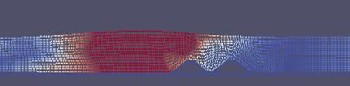
is illustrated in Figure 6.
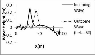
In the following figures, the incoming and outgoing waves in 6
states are illustrated. Also, the solution schema and the impact of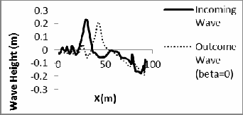
breakwater slope are presented in Figure 13 and Table 7.
Fig 8. Free-surface for the breakwater with a slope of 0 degree
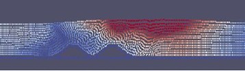
Fig 6. Solution schema
IJSER © 201
15
International Journal of Scientific & Engineering Research Volume śǰȱ ȱŗǰȱ ¢ȬŘŖŗŚȱȱȱȱȱȱ
ISSN 2229-5518
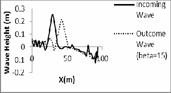
Fig 9. Free-surface for the breakwater with a slope of 15 degree
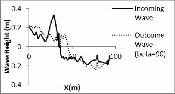
Fig13. Free-surface for the breakwater with a slope of 90 degree
Table 7. Slope influence comparison
![]()
![]()
1.07 1.18 1.29 1.32 1.47 1.50
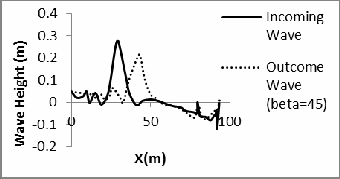
As it was shown in the above figures and in Table 7, the breakwa- ter's right-hand slope can reduce the wave height and as it was presented in the above table, a 90 degree slope has the maximum effect on reducing the height of incoming wave and oppositely, reducing this angle will reduce the effect so that at 0 degree the
Fig 10. Free-surface for the breakwater with a slope of 45 degree
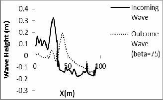
Fig11. Free-surface for the breakwater with a slope of 60 degree
Fig 12. Free-surface for the breakwater with a slope of 75 degree
effect will be minimized. The solution schema is shown in Figure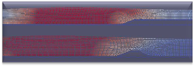
14.
Figure 14. The solution schema for two different back side angles
The aim of this study was to investigate the changes in the char- acteristics of solitary waves breaking over submerged breakwa- ters, using smoothed particle hydrodynamics method. First, the validity of solitary waves simulated using the smoothed particles hydrodynamics method, was examined using former numerical models. As it was shown, this method was able to simulate with a high accuracy. In the next step, the free-surface of solitary waves passing over submerged breakwaters was investigated. First, in order to confirm the accuracy of solution process, the results were compared to experimental results. Then the impact of the distance between two breakwaters on the reduction of wave height was investigated. As it was noted, when the distance be- tween two breakwaters falls between the spectrum of the wave- length of incoming wave, the second breakwater will have the
IJSER © 201
16
International Journal of Scientific & Engineering Research Volume śǰȱ ȱŗǰȱ ¢ȬŘŖŗŚȱȱȱȱȱȱ
ISSN 2229-5518
maximum effect. In the next step, the effect of the back side slope
of breakwater was examined. Based on the results of this study,
the smaller the angle of back side slope, the lesser the wave height
reduction and when this slope is at a right angle, the effect will be
maximized.
[1] Tokura, S. and Ida, T.2005. SIMULATION OF WAVE DISSIPATION MECH- ANISM ON SUBMERGED STRUCTURE USING FLUID-STRUCTURE COUPLING CAPABILITY IN LS-DYNA”, 5th EUROPEAN LS-DYNA.
[2] HARA, M., YASUDA, T. and SAKAKIBARA, Y.1992. CHARACTERISTICS OF
A SOLITARY WAVE BREAKING CAUSED BY A SUBMERGED OBSTA-
CLE”, COASTAL ENGINEERING.
[3] Hayakawa, N., Hosoyamada, T., Yoshida, S. and Tsujimoto, G.1998. Numerical Simulation of Wave Fields around The Submerged Breakwater with SOLA- SURF Method”, COASTAL ENGINEERING.
[4] Decheng, W. and Guoxiong, W.1998. Numerical simulation of solitary wave
interaction with submerged multi bodies”, journal of mechanical press.
[5] Armono, H. D. and Hall, K.R. 2002. Wave Transmission On Submerged Break- waters Made Of Hollow Hemispherical Shape Artificial Reefs”, Canadian Coastal Conference.
[6] YOSHIDA, A., YAN, S., yamashiro, M. and IRIE, I. 2002. Wave Field Behind a
Double-Submerged Breakwater”, International Offshore and Polar Engineer-
IJSER
ing Conference.
[7] Huang, C. J., Chang, H. H. and Hwung, H. H. 2003. Structural permeability effects on the interaction of a solitary wave and a submerged breakwater”, Coastal Engineering 49.
[8] Stamos, D. G., Hajj, M. R. and Telionis D. P. 2003. Performance of hemi-
cylindrical and rectangular submerged breakwaters”, Ocean Engineering 30.
[9] Johnson, H. K., Karambas, T. V., Avgeris, I., Zanuttigh, B., Gonzalez-Marco, D. and Caceres, I. 2005. Modelling of waves and currents around submerged breakwaters”, Coastal Engineering 52.
[10] Muni-Reddy, M.G. and Neelamani, S. 2006. Wave Interaction with Caisson
Defenced by an Offshore Low-Crested Breakwater”, Journal of Coastal Re- search.
[11] Chen, H.B., Tsai C.P. and Jeng C.C. 2007. Wave Transformation between Sub-
merged Breakwater and Seawall”, Journal of Coastal Research.
[12] Christou, M., Swan, C. and Gudmestad, O.T. 2008. The interaction of surface
water waves with submerged breakwaters”, Coastal Engineering 55.
IJSER © 201