International Journal of Scientific & Engineering Research, Volume 6, Issue 2, February-2015 103
ISSN 2229-5518
Simulation & Modelling of Deep Drawing Process of SMA Material
Chandra Pal Singh, Geeta Agnihotri
Abstract— This research work presents modeling of deep drawing of square cup. The sheet forming materials considered in study is NiTi shape memory alloy. The finite element analysis has been useful tool in simulating complex industrial forming operations. A simulation program has been carried out to study, effect of main process parameters such as blank holding pressure, coefficient if friction between sheet and die, on the thickness variation of cup wall and flange and to get maximum height of cup with minimum defects. The results of the study shows that uniform thinning of cup can be obtained by selecting proper combination of various process parameters.
Index Terms— Deep Drawing, Shape memory alloy, mechanical properties, square cups,Hypermesh,.
—————————— ——————————
1 INTRODUCTION
ne of the most common industrial processes in sheet metal forming is deep drawing. It can fabricate a variety of objects with cylindrical cups, rectangular cups even
complex shapes. [1],[2]. Deep drawing process (DDP) is de- fined as a manufacturing process in which a sheet metal work piece is pressed into a die cavity as seen in figure 1. In this process metal sheet is subjected to tensile and compressive stresses. The aim of successful deep drawing process is to produce a product with greater final depth as well as with less defects. When the length of drawn cup is greater than a half of the drawing punch diameter, the product is said to be deep drawn; otherwise the product is classified as a shallow part. In order to prevent the material blank from flowing freely into the die cavity through the process, a third forming tool, which is named blank holder, is employed to hold down the blank. This technique can be widely applied to manufacture metal products with an aspect ratio larger than unity. Currently, the deep drawing process has an extensive role in aerospace and automobile industries to manufacture structural components. There are many industrial products manufactured by sheet metal like car bodies, airplane wings, roofs, lab table and many more. To reach the new market requirements targets for the aerospace, rocket components, automotive body develop- ment, process integration since the early concept development phases until the start of production, must provide a stream- lined scalable environment that encompasses every step in the process from early design feasibility to the process final vali- dation. High safety standards, high reduction of weight that improves fuel consumption, emissions and performance trends, a world class quality at reasonable production costs and schedule timing are changing the development chain in the aerospace and automotive industry.
————————————————
• Chandra Pal Singh is currently pursuing Ph.D. Degree program in me- chanical engineering in MANIT, Bhopal, INDIA, PH-9826227054. E-mail: chandraid@gmail.com
• Dr. Geeta Agnihotri, Professor, Mechanical Department, MANIT, Bhopal,
INDIA.
Mainly regarding automotive lightweight construction based on the use of lightweight materials having low specific density and high-strength can be used. Automotive engineers and de- signers are being challenged every day and through the intro- duction of many new materials requirements can be fulfilled. Vehicle body complains usually complex geometry, irregular pressed parts. Forming these blanks is normally a combination of deep drawing and stretching and bending. A detailed anal- ysis and judging of the forming process with conventional processes requires a lot of energy for most cases. Process simu- lation in the forming technique with the Finite Element analy- sis is an efficient and low cost tool for simulation of the form- ing process before production. During all stages of the form- ing process before production the Finite elements analysis simulation enables a detailed judging of forming material, the optimal tool form and the process the control. A variety of ef- fects such as strain rate dependence of the material as well as different friction conditions at contact areas are describable and corresponding friction conditions are put at disposal by the programs. In this sense a consequent use of stamping sim- ulation enables: Saving of development time by securing the development course and to reduce costs as well as a quality improvement of stamping parts by optimization of process parameters, material choice, blank and forming steps of the deep drawing process.
Figure1:- Forming Process
IJSER © 2015 http://www.ijser.org
International Journal of Scientific & Engineering Research, Volume 6, Issue 2, February-2015 104
ISSN 2229-5518
2 DEEP DRAWING SIMULATION
2.1 Materials & Material Properties
In this present research work NiTi Shape Memory alloy is used. A NiTi Shape Memory Alloy (SMA) is able to memories and recovers its original shape, after it has been deformed by heating above its transformation temperature. The unique ef- fect of returning to an original geometry after a large inelastic
deformation (nearly about 10%) is known as the NiTi Shape Memory Effect [3]. The properties of NiTi and other SMA al- loys are fairly different, due to their different micro-structure. Because NiTi alloys have much higher strength, larger recov- erable strain, better corrosion resistance and most importantly higher reliability than other shape memory alloys. NiTi alloys are the standard choice for space and several other applica- tions. Materials and structures in many aerospace systems have mainly been responsible for large performance im- provements, because of reduction in gross weight and operat- ing costs. In the future these systems have to be small, inex- pensive and fast. The self-expanding antenna is one of the ex- ample that demonstrate SMAs have made inroads in the in- dustrial world [4]. Another technological challenge is an intel- ligent, self-healing vehicle where the SMA can be imbedded in the skin or substructures. It can detect damage and respond with an external stimulus for self-repair [5]. A commercially this technique can be used in automobile industries to make vehicle body parts. A vehicle part made of SMA can regain its shape on heating if damaged. Smart rotorcraft blades and air- craft wings will be one of the first applications of smart mate- rial in aerospace [6]. They could increase the maneuverability and controllability by changing the shape of their control sur- face. In this way it is possible to manipulate lift and twist. Or it can be used to reduce drag. In future aerospace vehicles will be made from programmable multifunctional materials and structures that will have the possibility to adjust their shape and mechanical, electromagnetic, optical and acoustic proper- ties on demand [7].
The material used in this study is smart material NiTi shape memory alloy. The mechanical properties are given in Table 1. E is the young’s modulus, Poisson’s ratio and Y is the yield stress of the material etc.
TABLE 1
THE MECHANICAL PROPERTIES OF NITI MATERIALS
2.2 Finite Element Model
A finite element simulation of deep drawing of “square cup” has been conducted using the high performance computer commercial software Hypermesh 12.0. Hypermesh provides manufacturing one step finite element analysis, which is com- petent for the computer aided analysis of sheet metal forming processes. The moldel geometry was drawn in 1:1 scale for the numerical model. The blank model was fine meshed and with 15979 elements. The drawing depth is 42mm and more than 42 mm, the contact gap was taken as 0.4 mm. A finite el- ement model of the geometry has been shown in figure 2.
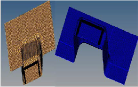
Figure 2:- FEA Model of Fine Meshing using Hypermesh
2.3 Simulation of deep drawing of square cup
Through Finite element simulation of square cups for different set of process parameters (blank holding force and friction between blank and die) have been observed. The Process modeled has been considered free from bulging and the com- pression, which can be occurred in actual practice. The FEM models are shown in Fig. 2, the blank was meshed using square shell elements with anisotropic material under plane stress conditions. The finite element simulation parameters of NiTi sheet have been given in the table.2.
TABLE 2
THE FINITE ELEMENTS PARAMETERS OF NITI SHEET MATERIALS
Material of sheet met- al | NiTi SMA |
Blanks of loads | 10, 12,15 kN |
Coefficients of friction | 0.12,0.15, 0.20 |
Sheet Thickness | 1 mm |
FE meshing elements | Square |
FE Meshing Size | 1 |
IJSER © 2015 http://www.ijser.org
International Journal of Scientific & Engineering Research, Volume 6, Issue 2, February-2015 105
ISSN 2229-5518

Sheet Metal Anistropic
In the study the effect of blank holder force and friction co- efficient have been investigated, for this the values of blank holder force has been taken as 10kN, 12kN, 15kN. Different blank holder force was selected to evaluate material flow rate, defects and drawing length.
3 RESULTS AND DISCUSSION
The blank holder force is the most important parameter in the sheet metal forming process. When blank holder force is insuf- ficient, there will be possibility of formation of wrinkles with poor quality of surface. If blank holder force is above some limiting value than there will be possibility of crack formation which leads to drawing failure. To determine the appropriate blank holder force, the blank holding device is loaded with
10kN, 15kN, 20kN and different coefficient friction respective- ly. The forming thinning ratio is achieved through post pro- cessing, as shown in Figure.3, 4 and 5. The forming thinning ratio and the maximum drawing height with various blank holder forces are shown in Table.3.
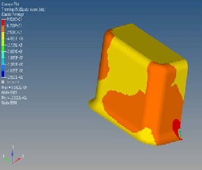
Figure 3:- The forming thinning ratio at load 10kN
at Coefficient of friction is 0.125
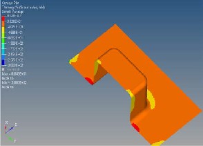
Figure 4:- The forming thinning ratio at load 12kN
at Coefficient of friction is 0.152
Figure 4:- The forming thinning ratio at load 15kN
at Coefficient of friction is 0.205
TABLE 3
FORMING THINNING RATIO AND MAXIMUM DRAW ING HEIGHT
Step | Blank Holder Force | Maximum Thinning Ratio | Minimum thinning Ratio | Height of cup |
| kN | % | % | mm |
1 | 10 | 9.5 | -2.0 | 42 |
2 | 12 | 8.0 | -3.0 | 45 |
3 | 15 | 8.7 | 1.3 | 48 |
From Table.3 and Figure.3, when blank holder force kept to
10 kN and friction as 0.125, It has been observed that the cup sidewall and the bottom surface thin most seriously and the maximum thinning ratio is 9.5%, where as flange area thickens and minimum thinning ratio is -2.0%., this region has wrin- kles. Results show that the blank holding force increases with the growth of the maximum thinning ratio and the reduction of the minimum thinning ratio. When the blank holding force is kept to 12kN in next set, the maximum thinning ratio is
8.0% but minimum thinning is -3.0% , this shows that thinning at side walls has been reduced and drawing depth increased but still there will be thickening at flange area that results in formation of wrinkles. As the blank holding force kept to 15 kN , it has been observed that maximum thinning is 8.7% and maximum thinning is 1.3%. The limit thinning ratio decreases and the maximum drawing height increases with the increas- ing of the coefficient of normal anisotropy. The dangerous area of breakage disappears and wrinkling still exists. But the area of wrinkling reduces greatly. It means that smaller the coeffi- cient of normal anisotropy, more easily the sheet changes in thickness.
IJSER © 2015 http://www.ijser.org
International Journal of Scientific & Engineering Research, Volume 6, Issue 2, February-2015 106
ISSN 2229-5518
4 CONCLUSION
Successful deep drawing depends on many parameters such as geometrical parameters and physical parameters. The finite element analysis simulation is a powerful tool in the sheet metal die design, reducing time and trial and error efforts. A Finite Element Model is developed to reach the optimum solu- tion without many costly trials of production which is a com- mon practice in the traditional production approaches. In this research work; simulation of the deep drawing process of the square cup has been carried out to discuss the influence of the blank holding force and the coefficient of normal anisotropy on the forming limit. The results show that: The limit thinning ratio decreases gradually and the deformation area tend to be scattered with the increase of blank holder load value and the coefficient of normal anisotropy. Also the trend of wrinkles in the local deformation area reduces and the maximum height increases, which is favorable to formation of sheet metal. The current model better describes the friction conditions related to sliding contacts surfaces in the deep drawing processes un- der lubricated conditions. In the present research work it has been observed that the optimum blank holding force should be kept upto 15 kN with increased friction coefficient as 0.205.
REFERENCES
[1] S.J. Alen and S.M Mahdavian. “The effect of lubrication of die expansion during the deep drawing of axisymmetrical steel cups”, Journal of materials procedure technology 2008; 199: 102-107.
[2] A.Fazli and B.Arezoo. “A comparison of numerical iteration based algorithms in blanks optimization”, Finite elements in analysis and design. 2012; 50:207-
2016.
[3] S. A. Thompson. “An overview of nickel–titanium alloys used in dentistry
International” Endodontic Journal.2000; 33: 297-310.
[4] W. Huang. “The selection of shape memory alloys for actuators. Materials and design”, 2002; 11:11-19.
[5] M.F-X Wagner, N.Nayan and U.Ramamurty. “Healing of fatigue damage in
NiTi shape memory alloys”, Journal of physics D: Applied Physics. 2008;
185408:4pp.
[6] Ken Gall, Jeff Tyber, Geneva Wilkesanders, Scott W. Robertson , Robert O.
Ritchie, and Hans J. Maier. “Effect of microstructure on the fatigue of hot- rolled and cold-drawn NiTi shape memory alloys”, Materials Science and Engineering A .2008; 486: 389–403.
[7] Gangbing Song, B.Kelly, B.N,Agrawal, P.C. Lam and T.S. Srivastav. “Applica- tion of shape memory alloy wire actuator for precision position control of a composite beam”. Journal of materials engineering and performance. 2000; 9:
330-333.
[8] Meinders, T., Vanden Berg, A., and Huetink, J. “Deep drawing simulations of tailored blanks and experimental verification”, Journal of Materials Processing Technology, 2000; 103: 65-73.
[9] Takuda, H., Mori, K., Masuda, I., Abe, Y and Matsuo, M. “Finite element
simulation of warm deep drawing of aluminum alloy sheet when accounting for heat conduction”, Journal of Materials Processing Technology. 2002;120:
412–418.
[10] F. Ayari, T. Lazghab and E. Bayraktar. “Parametric Finite Element Analysis of square cup deep drawing”, Computational materials science and surface engineering. 2009; 11(6):106-111.
[11] Y.Q. Guo, Y.M. Li, F. Bogard, and K. Debrey, “An efficient pseudo-inverse approach for damage modelling in the sheet forming process”, Journal of Ma-
terials Processing Technology. 2004; 151:88-97.
[12] E. Bayraktar and S.Altintas. “Square cup deep drawing and 2D draw bending analysis of Hadfield steel”, Journal of Materials Processing Technology.
1996;60:183-190.
[13] F. Fereshteh-Saniee and H.Bayateefar. Experimental comparison of different friction tests in bulk metal forming, Proceedings of the 7th International Con- ference “Technology of Plasticity”, Yokohama, 2002;1: 91-96.
[14] F. Fereshteh-Saniee, I. Pillinger and P.Hartley. “Friction modelling for the physical simulation of the bulk metal forming processes”, Proceedings of the International Conference Advances in Materials and Processing Technology.
2003; 1:543-546.
[15] Y. Yamaguchi, N. Takakura and M. Fakuda. “Attempts to facilitate low vol- ume production of soft aluminium cups with large draw ratios by deep draw- ing based on Maslennikov’s technique”, Journal of Mechanical Working Technology.1979;2: 357-366.
IJSER © 2015 http://www.ijser.org