International Journal of Scientific & Engineering Research, The research paper published by IJSER journal is about Simulation Approach for Quantifying the Homogeneity of In-cylinder Mixture Formation for Port Injected Diesel Fuel for PCCI/HCCI 1
ISSN 2229-5518
Simulation Approach for Quantifying the Homogeneity of In-cylinder Mixture Formation for Port Injected Diesel Fuel for PCCI/HCCI
B S Deshmukh, M K G Babu, M N Kumar, L M Das, Y V Aghav
Abstract— This paper analyzes the port injected diesel fuel mixture formation for advance combustion strategies like homogeneous charge compression ignition or premixed charge compression ignition system. The analysis combines the experimental as well as simulation approach. Focus of the study is to study the effect of different intake and fuel injection parameters on in-cylinder mixture homogeneity. The degree of in-cylinder mixture homogeneity is judged by the overall equivalence ratio and evaporation concentration. A 3- D simulation was carried out for port injected diesel fuel for fixed valve lift and steady state condition. The degree of homogeneity of in- cylinder mixture for port injected fuel is judged by the percentage volume occupied by the required equivalence ratio for different regions of total cylinder volume. The parametric simulation approach for intake air temperature, pressure, port wall temperature, fuel injection duration and fuel injection pressure is used to optimize the homogeneity of in-cylinder mixture. Based on the simulation study selected number of experiments have been carried out on an experimental engine to study the effect of part port and part incylinder diesel injection to achieve the ultra low emission of Oxides of Nitrogen (below 100 ppm) with HC and CO less than 1000 ppm for heavy duty constant speed application engine. At the same time the theoretical evaporation concept for the fuel droplet and its surrounding ambient gas is demonstrated and used for the better understanding of port injected diesel fuel mixture formation.
Index Terms— Euro IV, equivalence ratio, evaporation rate, fuel injection duration, fuel injection pressure, Homogeneous charge compression ignition (HCCI), intake air temperature, intake air pressure, Premixed charge compression ignition (PCCI), Port injection.
—————————— ——————————
New standards namely EURO V and beyond will require another order of magnitude reduction in both NOx and particulate matter emission as compared to existing stringent emission standards. These future standards are more challenging and will likely require a substantial development of after-treatment devices. One alternative for improving engine efficiency and emission is to change the combustion process itself completely, by means of advanced combustion strategies. The combustion of a homogeneous air/fuel mixture in the cylinder of a diesel engine is an attractive option to achieve this. The advance combustion strategies like HCCI / PCCI have been considered as a promising tool in achieving the ultra low emission. The success of these combustion strategies mainly depend on mixture formation and combustion phasing. In diesel engines, the injected fuel is developed with atomization, evaporation, diffusion and mixture formation by interactions between the fuel and ambient gas. Homogeneous or premixed charge can be obtained by early direct injection or port injection. Too early direct injection has a possibility to result into wash out
————————————————
Bhalchandra S. Deshmukh is with Kirloskar Oil Engines Ltd. Pune, India, and working in Corporate Research & Engineering, Heavy Duty Off-Highway Application Diesel Engine department. Phone:
+91-020-66084533 or +91-9881148180, Fax: +91-020-25813208, e-mail:
bhalchandra.deshmukh@kirloskar.com
Prof. M. K. Gajendra Babu, Formerly Professor and Head at IIT Delhi, Formerly Henry Ford Chair Professor at IIT Madras. mkgbabu8@gmail.com
Dr. M. N. Kumar and Dr. Y. V. Aghav are with Kirloskar Oil Engines
Ltd. Pune, India, and working as a Head of Corporate Research &
Engineering. M.kumar@kirloskar.com,Yogesh.aghav@kirloskar.com
phenomenon and late injection does not permit sufficient time for proper homogeneous charge mixture formation.
Port injection has a potential to form the homogeneous charge mixture required for HCCI / PCCI combustion. Ryan et al. (1996), Christense et al (1999) studied the premixed combustion phenomenon with diesel port injection and different intake temperature, Suzuki et al (1998) investigated premixed diesel fuel HCCI using GDI injector of 5 MPa combined with a normal DI diesel injection, the main thrust of these studies was to gain control of the timing of the premixed burn by setting it off with DI diesel injection. Kuneko et al. (2002) had shown the advantages of diesel fuel port injection in achieving cool combustion chemistry leading to a two stage ignition. Therefore, the focus of this study is to clearly make the process of mixture formation by undertaking equivalence ratio and evaporation rate of the port injected diesel fuel. As the droplets of injected fuel are dependent on the spray flow according to the droplet size, heterogeneous distribution of droplets in inner spray occurs. The dispersed droplets evaporate and the evaporated vapor also then forms the mixture by the entrainment of ambient gas. Therefore, the mixture analysis of the liquid and vapor phase is very important. However, only a few studies about mixture formation process have been done. Dan et al., (1996) studied non-evaporating fuel spray regardless of the phase change of actual diesel spray, Xiaolu Li et al., (2007) had conducted studies on diesel mixture formation at different fuel injection advance timing and Jeong Kuk Yeom et al., (2002) had dealt with the mixture formation process of evaporating diesel spray. However, these studies are either related with in- cylinder mixture formation or free spray mixture formation,
IJSER@2012 http://www.ijser.org
International Journal of Scientific & Engineering Research, The research paper published by IJSER journal is about Simulation Approach for Quantifying the Homogeneity of In-cylinder Mixture Formation for Port Injected Diesel Fuel for PCCI/HCCI 2
ISSN 2229-5518
they did not consider the port injected diesel fuel phenomenon and its effect on equivalence ratio and evaporation rate for mixture formation during IVO to IVC. Hence we studied mixture formation process of a port injected diesel fuel for the equivalence ratio and evaporation rate. Furthermore, in this study, a wide range of experimentation is carried out to study the effect of part port and part incylinder diesel fuel injection strategy in achieving the ultra low emission for Oxides of Nitrogen for heavy duty constant speed application engine.
the effect of intake air pressure with air boosting system. The jacket coolant heating system and 5 Kw intake air heating system allows to study the start ability phenomenon for different fuel injection sequences along with different compression ratio. The variable orifice control unit of Exhaust Gas Recirculation (EGR) allows to deliver a wide variety of EGR. Novel functionalities in terms of control were added to increase the flexibility of operations.
There are many ways of characterizing operating conditions and their influence on combustion. In the present case, where the effect of air management and injection strategies needed to be investigated, the hesitation was between conducting the programme in a ‘real’ multi-cylinder engine or in a ‘research’
Fuel metering system
Jackwet coolent heater system
Split fuel injection system
Exhaust Gas recirculation system
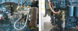
single-cylinder engine. Since the present focus was on evaluation of port injected diesel fuel and mixture formation simulation concept for the use of practical combustion system development, the multi-cylinder engine was selected. Considering the all variables in multi-cylinder configuration and with that achieving the required emission reduction, the multi-cylinder configuration is selected rather than limiting to the single cylinder research engine. This enabled the analyses to concentrate on the events in four cylinders on an average basis, which will be beneficial when working near the real combustion limits. A view of the multi-cylinder engine and facility is shown in Figure 1.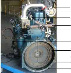
Air Boosting system
Split injection rail
Fuel injector
EGR System
Double Fuel injection
Pump
Jacket water eater
Flywheel Lubricating oil filter Crankcase
Flywheel housing
Figure 1: Experimental engine
The engine was modified for dual / twin injection system, which allows the direct fuel injection in port and incylinder also; it allows to do the split injection to study the different combustion phenomenon. It is very much possible to study
Figure 2: Features of Experimental engine
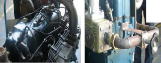
A test facility consists of an engine loading system, exhaust gas analyzers Horiba Hexa --- to monitor exhaust emissions data, and AVL, indicating system for collecting combustion and fuel injection parameters. The schematic diagram of the experimental set up is shown in Figure 3. Figure 4 indicates the instrumentation undertaken for the recording of indicator diagram with AVL advance indicating system. The cylinder pressure was measured using the uncooled AVL piezoelectric pressure transducer of type GM12D. The line pressure was recorded using the strain gauge pressure transducer from AVL of type 31DP2000-2.0. The needle lift was monitored by building in the injector a linearly variable differential transformer at the fuel injection equipment manufacturer, MICO BOSCH, India. The engine was loaded with an eddy current dynamometer regulated by a computerized controller, which maintains constant load or speed during the testing. A fast response throttle actuator was used to maintain different part throttle conditions. The coolant temperature was maintained by means of cooler and air ventilation system was used to maintain test cell ambient temperature. Controlled condition of intake air was maintained to standard conditions of pressure, temperature and humidity using an air conditioning system. The air-flow rate at inlet to engine was measured using sensyflow instrument. The sensyflow meters directly indicate the mass flow or normalized volume flow as the measuring signal. The system uses the ‚Hot Film‛ anemometer principle. This reliable technique is based on the fact that a flowing gas transfers heat from a heated object. This flow dependent heat loss is directly proportional to the gas mass flow rate. The mass measurement principle works without any additional pressure and temperature compensation. This technique provides important advantages
IJSER@2012 http://www.ijser.org
International Journal of Scientific & Engineering Research, The research paper published by IJSER journal is about Simulation Approach for Quantifying the Homogeneity of In-cylinder Mixture Formation for Port Injected Diesel Fuel for PCCI/HCCI 3
ISSN 2229-5518
of high measuring accuracy, wide measuring range, short
response time and negligible pressure loss. A fuel conditioning unit consisting of heat exchanger is employed to maintain the pressure and temperature of the fuel. The fuel flow was also measured by the gravimetric principle using load cell, solenoids and automated stop watch. For calculation of exhaust emission the total exhaust mass flow is required which is sum of intake air and fuel flow. A sample of exhaust was collected after the silencer in exhaust pipe to evaluate gaseous emissions and smoke. Gas analyzer based on heated Chemiluminescence, HCLA principle is used for measurement of NOx in engine exhaust. In present work heated flame ionization detector (HFID) was used to analyze the concentration of unburnt HC emission. The CO / CO2 measurement has been done with the gas analyzer based on the cross modulation system NDIR. Smoke is evaluated by using the opacity principle, in current study, AVL opacimeter
– 439 has been used to collect the smoke data.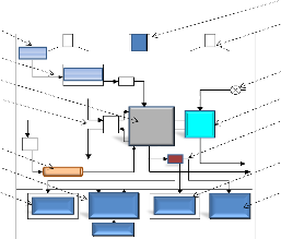
1
2
14
13
3
The equivalence ratio of an air fuel mixture for a particular engine load (fuelling) gives the indication of strength of that mixture. At the same time the uniform distribution of equivalence ratio indicates the quality of mixture. Normally, with port injected diesel fuel metering system, the fuel enters the air stream as a liquid jet. The liquid jet atomizes into droplets. These mix with the air and deposit on the walls of the intake system components. The droplets vaporize; partial vaporization of the liquid fuel on the walls occurs. The flow of liquid fuel along the walls can be significant. The transport of fuel as vapor, droplets, and liquid streams or films can all be important. The fuel transport processes in the intake system are obviously extremely complex. The liquid fuel is injected in the inlet port with single spray pintle type nozzle, towards rare surface of the intake valve, whereas for incylinder fuel injection multi hole injector is preferred. For all these practical fuel metering systems the quality of the mixture entering the engine is imperfect. The fuel air mixture in not homogeneous; the fuel may not be fully vaporized as it enters the engine. The charge going into the engine is not usually uniform in air/fuel
12
11
10
9
8
Figure 3: Experimental set up
4 ratio throughout its volume. Figure 5 demonstrate the theoretical phenomenon for diesel fuel spray disintegration
5
based on actual pintle nozzle spray used for this study. Figure
5 (A) shows the actual spray emerging from the pintle nozzle,
6 with an injection pressure of 15 MPa. The spray is surrounded by the ambient gas of 0.1 MPa pressure and 300 K
7
temperature. Figure 5 (B) shows the different spray envelops
for fully developed fuel spray. As shown, section XX
represents the fuel intensity in spray envelops. ‚A‛ indicates the 100% liquid fuel and ‚E‛ indicates the ambient gas with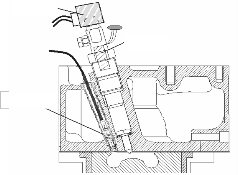
1-Exhaust blower, 2-Cooling air blower, 3-water flow control valve, 4-Dynamometer, 5-Engine exhaust, 6-AVL smoke meter, 7-Particulate measurement unit, Gas analyzer, 8-Dyno controller, 9- Display unit, 10-Fuel conditioning unit, 11-Water cooler, 12-Engine, 13-Plannum chamber, 14-Air conditioning unit.
Fuel pressure
sensor
Niddle lift sensor
Cylinder pressure sensor
Figure 4: Instrumentation for indicator diagram
some traces of fuel. Within the vicinity of different envelops of the spray the fuel spray start disintegrating from liquid spray to bigger, smaller and finer droplets as shown in Figure 5 (C). The liquid fuel drops are accelerated by the surrounding air stream and start to vaporize. The surrounding air motion, temperature and pressure govern the degree of atomization, vaporization and mixing of liquid fuel. Due to the heat transfer the droplet temperature increases, the fuel vapor pressure increases and the evaporation rate increases. As the mass transfer rate of vapor away from the drop increases, so the fraction of the heat transferred to the drop surface which is available to increase further the drop temperature decreases. As fuel vaporizes, the local air temperature will decrease and the local fuel vapor pressure will increase. Eventually thermodynamic equilibrium would pertain: this is usually called adiabatic saturation. Wakil EI et al. (1967) studied fuel vaporization and ignition lag in diesel combustion and demonstrated the adiabatic saturation phenomenon. The degree of vapor saturation in the ambient gas governs the
IJSER@2012 http://www.ijser.org
International Journal of Scientific & Engineering Research, The research paper published by IJSER journal is about Simulation Approach for Quantifying the Homogeneity of In-cylinder Mixture Formation for Port Injected Diesel Fuel for PCCI/HCCI 4
ISSN 2229-5518
strength of that mixture. The strength of mixture never is the
uniform for complete cylinder volume. This non uniformity enhances the degree of heterogeneity. Thus following parameters are necessary to study and optimize in defining the quality of mixture of port injected diesel fuel.
Uniformity of mixture strength
Evaporation of port injected fuel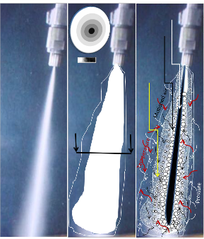
(A) (B) (C)
Calculation starts at 5 deg CA BTDC considering the 50%
valve lift of total valve lift. In calculation process diesel is used as fuel. When simulating the condition the intake port conditions assumed are 298 K temperature and 0.1 MPa pressure. The fuel injection starts 90 deg CA ATDC and ends at 113 deg CA ATDC, with injection pressure of 15 MPa. Other simulation parameters for respective case are shown in Table
1.
D C B A E
Liquid jet
Bigger Droplet
from liquid jet
Min
F
Max
X X
Smaller & finer Drople surrounded by ambient gas
Table 1: Simulation parameter for different cases
A detailed simulation was carried out for the port injected
A diesel fuel corresponding to different cases mentioned in
B
C Table 1. The Case A has been considered as the base case and
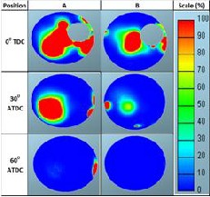
D comparison has been done for the remaining cases with variants as indicated in the Table 1. The simulation has been done to study the effect of port wall temperature as represented by case ‚A‛ and case ‚B‛. Figures 7 to 9 show the vapour concentration at different crank angle like 80 deg, 120
Figure 5: Pintle nozzle spray disintegration and mixture
formation sequence
Three-dimensional model of in-cylinder flow is based on classic fluid dynamics, namely the continuity, momentum and energy equations. The AVL-Fire (CFD-WM) simulation tool is used for the port injected diesel fuel and ambient gas flow analysis. The WAVE child break up model is used to simulate the process of fuel spray, which is consists of disperse particles. The wall jet model includes the flow, collision, breakup, and evaporation. The steady state flow analysis is performed for each set of simulation parameters for a particular valve lift. The work flow is described in Figure 6.
3D CAD data
deg and 180 deg, for the cases ‚A‛ and ‚B‛. The effect of port wall temperature is clearly visible from the results. The higher port wall temperature helps in an improved vaporization of port injected fuel and thus helps in achieving the higher spread of fuel vapour in total air-fuel mixture.
Variation of
1. Intake ambient gas temperature
2. Intake ambient gas pressure
3. Fuel quantity
CFD model generation
Set up of boundary condition
Simulation of steady flow for various valve lifts
With intake system
Test bed condition
Mixture formation
1. Equivalance
ratio distribution
2. Evaporation rate
Figure 6: Work flow for port injected diesel fuel mixture
formation simulation
Figure 7: Effect of Port Wall Temperature on Vapour
Concentration at 80 deg crank angle
IJSER@2012 http://www.ijser.org
International Journal of Scientific & Engineering Research, The research paper published by IJSER journal is about Simulation Approach for Quantifying the Homogeneity of In-cylinder Mixture Formation for Port Injected Diesel Fuel for PCCI/HCCI 5
ISSN 2229-5518
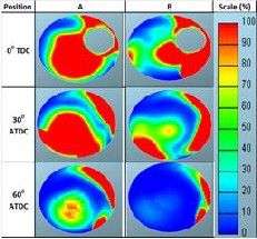
Figure 8: Effect of Port Wall Temperature on Vapour
Concentration at 120 deg crank angle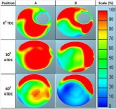
Figure 9: Effect of Port Wall Temperature on Vapour
Concentration at 180 deg crank angle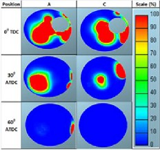
Figure 10: Effect of Fuel Injection Pressure on Vapor
Concentration at 80 deg crank angle
Figure 11: Effect of Effect Fuel Injection Pressure on Vapor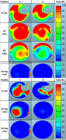
Concentration at 120 deg crank angle
Figure 12: on Vapor
Concentra
Figure 13: Effect of intake air Pressure on Vapor Concentration at 80 deg crank angle
IJSER@2012 http://www.ijser.org
International Journal of Scientific & Engineering Research, The research paper published by IJSER journal is about Simulation Approach for Quantifying the Homogeneity of In-cylinder Mixture Formation for Port Injected Diesel Fuel for PCCI/HCCI 6
ISSN 2229-5518
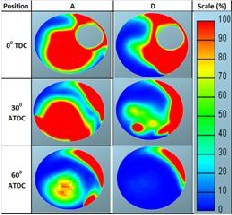
Figure 14: Effect of intake air Pressure on Vapor Concentration at 120 deg crank angle.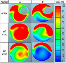
Figure 15: Effect of intake air Pressure on Vapor Concentration at 180 deg crank angle.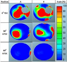
Figure 16: Effect of Intake Air Temperature on Vapor
Concentration at 80 deg crank angle.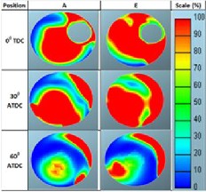
Figure 17: Effect of Intake Air Temperature on Vapor
Concentration at 120 deg crank angle.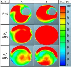
Figure 18: Effect of Intake Air Temperature on Vapor
Concentration at 180 deg crank angle.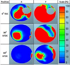
Figure 19: Effect of Intake Air Temperature and injection duration on Vapor Concentration at 80 deg crank angle.
IJSER@2012 http://www.ijser.org
International Journal of Scientific & Engineering Research, The research paper published by IJSER journal is about Simulation Approach for Quantifying the Homogeneity of In-cylinder Mixture Formation for Port Injected Diesel Fuel for PCCI/HCCI 7
ISSN 2229-5518
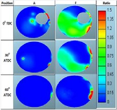
16 to 18. When higher intake air temperature is coupled with the lesser fuel injection duration, (case ‚F‛) the optimum results have been observed. Figures 19 to 20, indicate the 100% spread of vapour concentration for complete mixture and thus helps in increasing the homogeneity of the overall mixture.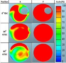
Figure 20: Effect of Intake Air Temperature and injection duration on Vapor Concentration at 120 deg crank angle.
Figure 22: Effect of Port Wall Temperature on Equivalence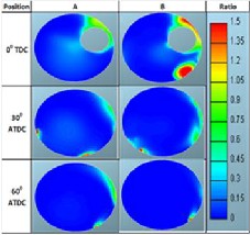
Ratio at 80 deg crank angle
Figure 21: Effect of Intake Air Temperature and injection duration on Vapor Concentration at 180 deg crank angle.
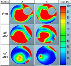
Higher the fuel injection pressure better is the atomization, as
shown in case ‚A‛. A 150 bar fuel injection pressure and
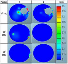
higher port wall temperature show a better vaporization characteristics as compared to case ‚C‛ with 100 bar injection pressure, the trends are shown in Figures 10 to Figure 12. Whereas, when the intake air pressure increases the result shows the lesser spread for the vapour concentration in the mixture. This may be because of higher air pressure moves the fuel particles along the stream and get localized at one place. From the vapour concentration of case ‚D‛ the higher degree of vapour concentration localization is seen exactly in the direction of air stream heating around the intake valve and liner side (Figure 13 to Figure 15). Case ‚E‛ represents the higher intake temperature, port wall temperature and injection pressure. The increase in intake air temperature shows the positive results and increases the vapour concentration throughout the mixture. At all crank angles the higher intake air temperature results in a wide spread of vapour concentration in air fuel mixture, as shown in Figures
Figure 23: Effect of Port Wall Temperature on Equivalence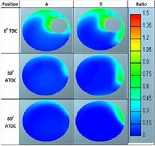
Ratio at 120 deg crank angle
Figure 24: Effect of Port Wall Temperature on Equivalence ratio at 180 deg Crank angle
IJSER@2012 http://www.ijser.org
International Journal of Scientific & Engineering Research, The research paper published by IJSER journal is about Simulation Approach for Quantifying the Homogeneity of In-cylinder Mixture Formation for Port Injected Diesel Fuel for PCCI/HCCI 8
ISSN 2229-5518
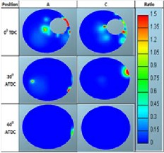
Figure 25: Effect of Fuel Injection Pressure on Equivalence
Ratio at 80 deg Crank angle.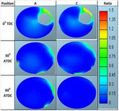
Figure 26: Effect of Fuel Injection Pressure on Equivalence
Ratio at 120 deg Crank angle.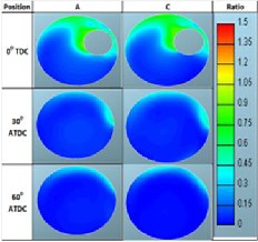
Figure 27: Effect of Fuel Injection Pressure on Equivalence
Ratio at 180 deg Crank angle.
Figure 28: Effect of Intake Air Pressure on Equivalence Ratio at
80 deg Crank angle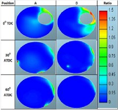
Figure 29: Effect of Intake Air Pressure on Equivalence Ratio at
120 deg Crank angle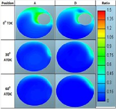
Figure 30: Effect of Intake Air Pressure on Equivalence Ratio at
180 deg Crank angle
IJSER@2012 http://www.ijser.org
International Journal of Scientific & Engineering Research, The research paper published by IJSER journal is about Simulation Approach for Quantifying the Homogeneity of In-cylinder Mixture Formation for Port Injected Diesel Fuel for PCCI/HCCI 9
ISSN 2229-5518
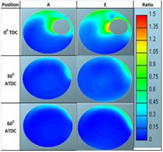
Figure 31: Effect of Intake Air Temperature on Equivalence
Ratio at 80 deg Crank angle.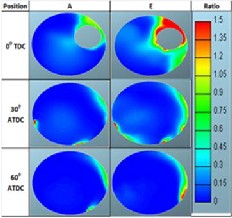
Figure 32: Effect of Intake Air Temperature on Equivalence
Ratio at 120 deg Crank angle.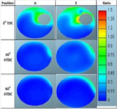
Figure 33: Effect of Intake Air Temperature on Equivalence
Ratio at 180 deg Crank angle
Figure 34: Effect of Intake Air Temperature and Fuel Injection
Duration on Equivalence Ratio at 80 deg Crank angle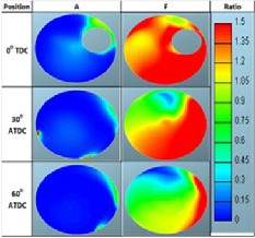
Figure 35: Effect of Intake Air Temperature and Fuel Injection
Duration on Equivalence Ratio at 120 deg Crank angle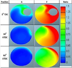
Figure 36: Effect of Intake Air Temperature and Fuel Injection
Duration on Equivalence Ratio at 120 deg Crank angle
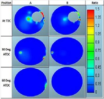
Along the vapour concentration the overall equivalence ratio
IJSER@2012 http://www.ijser.org
International Journal of Scientific & Engineering Research, The research paper published by IJSER journal is about Simulation Approach for Quantifying the Homogeneity of In-cylinder Mixture Formation for Port Injected Diesel Fuel for PCCI/HCCI 10
ISSN 2229-5518
of the mixture was also analyzed. Similar results have been confirmed for the spread of the equivalence ratio for air and fuel mixture for different cases. Figures 22 to 24, show the positive effect of port wall temperature on the overall
respective cases, which had resulted in knocking and excessive noise interference, as depicted in Figure 38.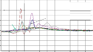
120
equivalence ratio of the mixture. Whereas Figure 25 to Figure
27, and Figure 28 to Figure 30, show the effect of fuel injection
pressure and intake air pressure. Case ‚E‛ represents the
higher intake temperature, port wall temperature and
injection pressure. The increase in intake air temperature
shows the positive results and increases the homogeneity of
the mixture. For all crank angles the higher intake air
temperature results in a uniform equivalence ratio as shown in
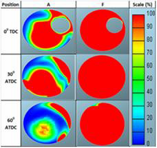
Figures 31 to 33. The effect of intake air temperature along
with the lesser injection duration shows the uniform strength
of incylinder air and fuel mixture, which depicted in Figures
100
80
60
40
20
0
-20
-40
-60
-80
Poor BTE Useful BTE
Early HR
Ultra low NOx
emission state
FILENAME
4R1040_Bhal_HCCI.005
4R1040_Bhal_HCCI.006
4R1040_Bhal_HCCI.013
4R1040_Bhal_HCCI.017
4R1040_Bhal_HCCI.023
4R1040_Bhal_HCCI.029
34 to 36. Thus the study indicates that the homogeneous
mixture can be achieved for the port injected diesel fuel with
proper optimization of related parameters as mentioned in the
research study. With this the experimentation was undertaken
to analyze the effect of part port and part incylinder diesel fuel
injection for the ultra low NOx emission of 100 ppm and HC
and CO emission limited to less than 1000 ppm.
6.1 PPPCI Combustion – 2.3 bar bmep
The experimentation has been done for different operating windows of heavy duty constant speed application engine. The operating windows have been defined based on the bmep level for this particular engine. The experimentation has been started for a load window of 2.3 bar bmep. The different PPPCI conditions have been tested for the engine performance, combustion and emission, as given in Table 2. As mentioned earlier the experimental engine consist of two fuel injection pump, Pump 1 is for the incylinder fuel injection and Pump 2 is for the port fuel injection. The injector with spray cone angle (SCA) of 100 deg has been used for the main injection with compression ratio (CR) 14. Both, SCA and CR has been derived and used for the experimentation based on rigorous experimentation for the low compression ratio, advance fuel injection timing and its effect on fuel dilution and startability of the engine. Figure 37 shows the instantaneous heat release rate for the different PPPCI test conditions. The part port and advance fuel injection timing for main injection resulted in the main heat release occurrence at 2 to 5 deg. before top dead center (TDC) and this lead to poorer brake thermal efficiency. Some of the instantaneous HRR shows the
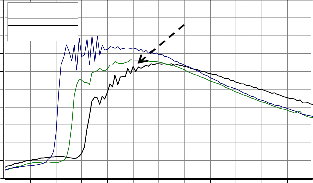
negative trend which may be due to a very high dp/dϴ for
-30 -20 -10 -0 10 20 30 40 50 60 70 80 90
Crank Angle [deg]
Figure 37: Instantaneous HRR for different PPPCI condition at
2.3 bar bmep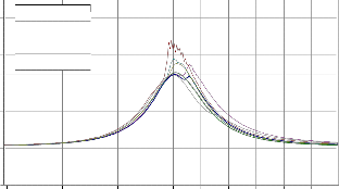
80
FILENAME
70
4R1040_Bhal_HCCI.005
4R1040_Bhal_HCCI.006
60
4R1040_Bhal_HCCI.013
4R1040_Bhal_HCCI.017
50 4R1040_Bhal_HCCI.023
4R1040_Bhal_HCCI.029
40
30
20
10
0
-10
-20
-120 -100 -80 -60 -40 -20 0 20 40 60 80 100
Crank Angle [deg]
Figure 38: In-cylinder pressure for different PPPCI condition at 2.3 bar bmep
Parameters | Test_1 | Test_2 | Test_3 | Test_4 | Test_5 | Test_6 | Test_7 | Test_8 |
SCA (deg) | 100 deg | 100 deg | 100 deg | 100 deg | 100 deg | 100 deg | 100 deg | 100 deg |
CR (-) | 14 | 14 | 14 | 14 | 14 | 14 | 14 | 14 |
Pump 1(deg) | 20 | 20 | 20 | 20 | 30 | 40 | 50 | 10 |
Pump 2 (deg) | 180 | 180 | 180 | 180 | 180 | 180 | 180 | 120 |
Boost (mm of Hg) | 300 | 355 | 624 | 614 | 475 | 525 | 400 | 650 |
Air Temp (deg C) | 50 | 85 | 100 | 125 | 125 | 100 | 60 | 150 |
EGR (%) | 0 | 0 | 0 | 0 | 0 | 0 | 0 | 0 |
Table 2: Test matrix for the PPPCI and 2.3 bar bmep engine load window
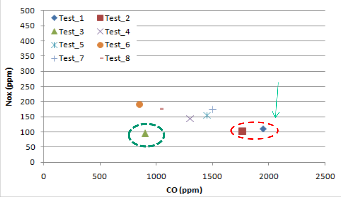
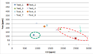
Test number 3 shows very positive results for the NOx emission. The NOx emission recorded for test no. 3 is below
100 ppm and the HC and CO emissions are well below the
1000 ppm. From instantaneous HRR, the highlighted curve indicates the lower heat release rate for the port injected fuel and the same gets propagated smoothly for the main injection
IJSER@2012 http://www.ijser.org
International Journal of Scientific & Engineering Research, The research paper published by IJSER journal is about Simulation Approach for Quantifying the Homogeneity of In-cylinder Mixture Formation for Port Injected Diesel Fuel for PCCI/HCCI 11
ISSN 2229-5518
which resulted in a low NOx emission. Whereas some of the
portion of heat release continue in diffusion combustion and thus the HC and CO emissions are high as compared to the normal combustion, which is shown in Figures 40 and 41. Thus the experimentation results also have shown the positive results for the combustion and emission inline to the simulation approach of achieving the homogeneous mixture for HCCI / PCCI combustion.
around 100 ppm and HC and CO emissions less than 1000
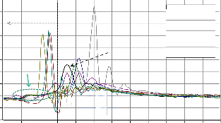
ppm for the 3.4 bar bmep engine load condition, as portrayed in Figures 44 and 45. The corresponding instantaneous HRR, highlighted curve, Figure 42, indicates the low heat release for the port injected fuel and the same gets propagated smoothly for the main injection and resulted in low NOx emission.
White Smoke
Table 3: Test matrix for the PPPCI and 3.4 bar bmep engine
load window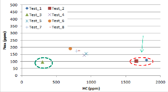
Figure 40: NOx and HC emission for different PPPCI
160
140
Poor BTE Useful BTE
FILENAME
condition at 2.3 bar bmep
120
100
80
60
40
Early HR
Ultra low NOx
emission state
4R1040_Bhal_HCCI.001
4R1040_Bhal_HCCI.002
4R1040_Bhal_HCCI.003
4R1040_Bhal_HCCI.014
4R1040_Bhal_HCCI.020
4R1040_Bhal_HCCI.026
4R1040_Bhal_HCCI.032
4R1040_Bhal_HCCI.039
20
White Smoke 0
-20
-40
-30 -20 -10 -0 10 20 30 40 50 60 70 80 90
Crank Angle [deg]
Figure 42: Instantaneous HRR for different PPPCI condition at
3.4 bar bmep
Figure 41: NOx and CO emission for different PPPCI
condition at 2.3 bar bmep
6.1 PPPCI Combustion – 3.4 bar bmep
The next stage of experimentation has been done for the load window of 3.4 bar bmep. The different PPPCI conditions have been tested for the engine performance, combustion and emission are listed in Table 3. Similar observations have been noticed for the case of 3.4 bar bmep at different test conditions. Very high intake air temperature and advance fuel injection timing of main injection resulted in early main heat release, as shown in Figure 42 and which also resulted into knocking phenomenon, as indicated in Figure 43. With lower intake air temperature the HC and CO emissions are observed to be more than 2000 ppm. Test 1, shows a NOx emission just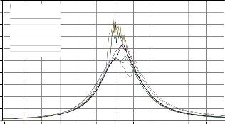
80
FILENAME
72
4R1040_Bhal_HCCI.001
4R1040_Bhal_HCCI.002
64
4R1040_Bhal_HCCI.003
4R1040_Bhal_HCCI.014
56 4R1040_Bhal_HCCI.020
4R1040_Bhal_HCCI.026
48 4R1040_Bhal_HCCI.032
4R1040_Bhal_HCCI.039
40
32
24
16
8
0
-120 -100 -80 -60 -40 -20 0 20 40 60 80 100
Crank Angle [deg]
Figure 43: Cylinder pressure for different PPPCI condition at
3.4 bar bmep
Thus the well optimized intake air temperature and pressure helps better air and fuel mixture formation and resulted into
IJSER@2012 http://www.ijser.org
International Journal of Scientific & Engineering Research, The research paper published by IJSER journal is about Simulation Approach for Quantifying the Homogeneity of In-cylinder Mixture Formation for Port Injected Diesel Fuel for PCCI/HCCI 12
ISSN 2229-5518
smooth combustion with less than 100 ppm NOx emission and
HC and CO well below the 1000 ppm.
White Smoke
Table 4: Test matrix for the PPPCI for 4.2 bar bmep engine load window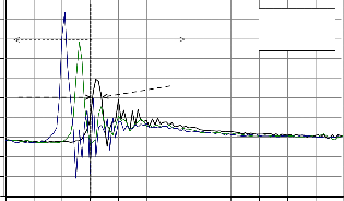
210
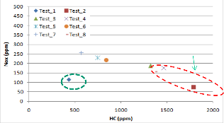
Figure 44: NOx and HC emission for different PPPCI
180
150
120
Poor BTE Useful BTE
FILENAME
4R1040_Bhal_HCCI.050
4R1040_Bhal_HCCI.054
4R1040_Bhal_HCCI.058
condition at 3.4 bar bmep
90 Early HR delayed
by EGR
Ultra low NOx
emission state
60
30
0
-30
White Smoke
-60
-90
-30 -20 -10 -0 10 20 30 40 50 60 70 80 90
Crank Angle [deg]
Figure 46: Instantaneous HRR for different PPPCI condition at
4.2 bar bmep
Figure 45: NOx and CO emission for different PPPCI
condition at 3.4 bar bmep
6.2 PPPCI Combustion – 4.2 bar bmep
Further to previous analysis, it is observed that as the quantity of fuelling increases the combustion is becoming more unstable and also the early heat release becoming dominating, which results in a higher NOx emission. To suppress further the early heat release rate with higher fuelling, it was decided to introduce the EGR and do the analysis for the engine load window of 4.2 bar bmep. Table 4 shows the test matrix for the
4.2 bar bmep operating window. The advance fuel injection timing for the main injection along with the port fuel injection leads to knocking and the observed dp/ dϴ is beyond 10 bar. The corresponding NOx emission is also very high. With the retarded main fuel injection timing and introduction of EGR delayed the main HRR which results in the fall of cylinder gas temperature as could see in Figure 47.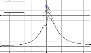
90
FILENAME
80
4R1040_Bhal_HCCI.050
4R1040_Bhal_HCCI.054
70
4R1040_Bhal_HCCI.058
60
50
40
30
20
10
0
-10
-120 -100 -80 -60 -40 -20 0 20 40 60 80 100
Crank Angle [deg]
Figure 47: Cylinder pressure for different PPPCI condition at
4.2 bar bmep
IJSER@2012 http://www.ijser.org
International Journal of Scientific & Engineering Research, The research paper published by IJSER journal is about Simulation Approach for Quantifying the Homogeneity of In-cylinder Mixture Formation for Port Injected Diesel Fuel for PCCI/HCCI 13
ISSN 2229-5518
1600
1500
1400
1300
1200
1100
FILENAME
4R1040_Bhal_HCCI.050
4R1040_Bhal_HCCI.054
4R1040_Bhal_HCCI.058
Effect of EGR
The theoretical approach of pintle nozzle spray disintegration and mixture formation sequence helps in understanding the phenomenon of air and fuel interaction in its vicinity.
1000
900
800
700
600
-30 -20 -10 -0 10 20 30 40 50 60 70 80 90
Crank Angle [deg]
The study reveals that, the simulation approach for defining the overall homogeneity for the port injected diesel fuel helps in understanding the key parameters and its effect on incylinder mixture formation. Parameters like intake air temperature and pressure, fuel
Figure 48: Cylinder pressure for different PPPCI condition at
4.2 bar bmep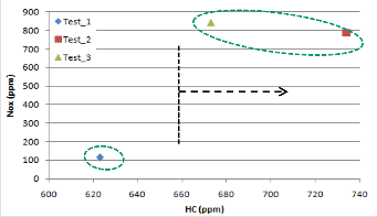
Optimized Air boosting, Intake Temperature and moderate EGR shows NOx emission is less than 110 ppm and HC and CO emission less than 1000 ppm for 4.2 bar bmep operating window, as depicted in Figure 49 and Figure 50. Beyond 4 bar bmep with PPPCI leads heavy penalty to fuel consumption and abnormal combustion.
High fuelling dp /dϴ > 10 bar
Figure 49: NOx and HC emission for different PPPCI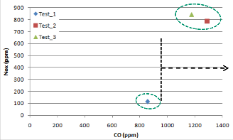
condition at 4.2 bar bmep
High fuelling dp /dϴ > 10 bar
injection pressure and duration are the key parameters for achieving the homogeneous mixture for the case of port injected diesel fuel. Intake air temperature and the injection duration, play a vital role in the improved better vaporization of the port injected diesel fuel. From results it is depicted that better vaporization results into wide sprayed uniform air fuel mixture for different crank angle and result into overall homogeneity.
The experimentation portrayed the successful concept of port injected diesel fuel along with incylinder fuel injection in achieving the HCCI / PCCI and ultra low NOx emission with HC and CO emission well below the
1000 ppm. At 2.3 bar bmep, the results for different test case indicates that the homogeneity of port injected diesel fuel is the result of optimum condition of intake parameters for particular fuelling and thus results into smooth combustion and ultra low NOx emission state with acceptable HC and CO emission. Similar, observation has been perceived at 3.4 bar bmep, which is
50% load window for this engine. As the fueling
increases the early combustion with very high knocking is observed for the same compression ratio used for the lower fuelling. The use of moderate exhaust gas recirculation (EGR) with PPPCI help in suppressing the early start of combustion, the results of 4.2 bar bmep window confirms the same.
The study helped in understanding the possibility of achieving the homogeneity with diesel as a fuel and part port injection as a methodology to achieve the ultra low NOx emission for heavy duty constant speed application engine under 60% load condition. Further expansion of the simulation approach upto exhaust valve opening (EVO) with suitable combustion and emission model may help in detailing the complete combustion strategy with PPPCI for complete operating window.
Figure 50 : NOx and CO emission for different PPPCI
condition at 4.2 bar bmep
IJSER@2012 http://www.ijser.org
International Journal of Scientific & Engineering Research, The research paper published by IJSER journal is about Simulation Approach for Quantifying the Homogeneity of In-cylinder Mixture Formation for Port Injected Diesel Fuel for PCCI/HCCI 14
ISSN 2229-5518
1. Ryan III, T. W. and Challahan, T. J., ‚Homogenous charge compression ignition of diesel fuel‛, SAE Technical Paper, No. 961160 (1996).
2. Suzuki H., Koike, N and Odaka, M, ‚Combustion control method of homogenous charge diesel engines‛, SAE Technical Paper, No.980509 (1998)
3. Browne, K., R., Partridge, I., M., Greeves, G. (1986) ‚Fuel Property Effects on Fuel/Air Mixing in an Experimental Diesel Engine‛, SAE Paper 860223.
4. Kaneko N., and, H., and Miyamoto, N., ‚Expansion of the operating range with in-cylinder water injection in a premixed charge compression igntion engine‛, SAE Technical Paper No. 2002-01-1743 (2002)
5. Xiaolu Li, Jianguo Xing, Tao Hong, ‚Simulation and comparison of diesel mixture formation at different fuel injection advance angles‛, International journal of mathematics and computer in simulation, Issue 3, Volume 1, 2007.
6. Jeong-Kuk Yeo, Byung-Mu Kang, Sung-Sik Chung, Jong- Yul Ha, Hajime Fujimoto, ‚A Study on the Mixture Formation Process of Evaporating Diesel Spray by Offset Incidence Laser Beam‛, KSME International Journal, Vol.
16 No. 12, pp. 1702~ 1709, 2002.
7. Takeda, Y., Keiichi, Na., Keiichi, Ni. (1996) ‚Emission Characteristics of Premixed Lean Diesel Combustion with Extremely Early Staged Fuel Injection‛, SAE Paper
961163.
8. Aoyama, T., Hattori, Y., Mizuta, J., Sato, Y. (1996) ‚An Experimental Study on Premixed-Charge Compression Ignition Gasoline Engine‛, SAE Paper 960081.
9. Suzuki, H., Koike, N., Ishii, H., Odaka, M. (1997)
‚Exhaust Purification of Diesel Engines by Homogeneous Charge with Compression Ignition Part 1: Experimental Investigation of Combustion and Exhaust Emission Behavior Under Pre-Mixed Homogeneous Charge Compression Ignition Method‛, SAE Paper 970313.
10. Yokota, H., Kudo, Y., Nakajima, H., Kakegawa, T., Suzuki, T. (1997) ‚A New Concept for Low Emission Diesel Combustion‛, SAE Paper 970891.
11. Iwabuchi, Y., Kawai, K., Shoji, T., Takeda, Y. (1999) ‚Trial
of New Concept Diesel Combustion System – Premixed
Compression-Ignited Combustion‛, SAE Paper 1999-01-
0185.
12. Epping, K., Aceves, S., Bechtold, R., and Dec, J., ‚The potential of HCCI combustion for high efficiency and low emissions,‛ SAE technical paper No. 2002-01-1923 (2002).
13. Alperstein, M. Siwim, W. B., Schweitzer, P.H.,
‚Fumigation kills smoke improves diesel combustion,‛
SAE Transactions, Vol 66, PP. 574-595 (1958).
14. Ryan III, T. W. and Challahan, T. J., ‚Homogenous charge compression ignition of diesel fuel,‛ SAE Technical Paper, No. 961160 (1996).
15. Gray A. and Ryan III, T. W., ‚Homogeneous charge compression ignition (HCCI) of diesel fuel,‛ SAE Technical Paper, No. 971676(1997).
16. Nakagome K., Shimazaki, N, Niimura, K., and Kobayashi, S., ‚Combustion and emission characteristics of premixed lean diesel combustion engine,‛ SAE Technical Paper, No. 970898 (1997).
17. Mase, Y., Kawashina, J. I., Sato, T and Euguchi, M.,
‚Nissan’s new multivalve DI diesel engine series‛, SAE
Technical Paper, No. 981039 (1998).
IJSER@2012 http://www.ijser.org