International Journal of Scientific & Engineering Research, Volume 4, Issue 8, August-2013 1816
ISSN 2229-5518
Segmenting and Tracking People in Surveillance
System Using Optical Flow Technique
Reemamol P.K, Sayana sivanad, Benoy Abraham
![]()
Surveillance systems are very common in our day today life. They are made for the security and safety of people. In our approach surveillance video from the CCTV camera is used as the input. Since the video will have more occlusions we have to separate them individually and represent each individual as separate people. There are so many approaches to extract the foreground moved region like background subtraction, feature based extraction and optical flow technique. In our paper we are using combination of optical flow and background subtraction algorithms.
We have done the project in the MATLAB Simulink. So that it is much easier for the process done.
Our system overview is shown in Fig No: 1. in our system the input video is given to the foreground detector and the output shows a rectangle which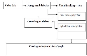
Fig No:1 system overview![]()
• Reemamol P.K is currently pursuing masters degree program in communication engineering in MG University, India. E-mail: reema231990@gmail.com.
• Sayana sivanand is currently pursuing masters degree program in communication engineering in MG University, India.
• Benoy Abraham is working as the assistant professor in Electronics and communication department of FISAT, mookkannoor
contains moved area may be one person or moving a group
of people in a single rectangle. Next is the visual tracking system which includes basic tracking algorithm and optical flow technique. Basic tracking algorithm is used to track people in different frames and optical flow technique is used to track the segmented people in the same frame.
If the foreground estimator rectangle have more than one people the output goes to the crowd segmentation unit where the people are identified in separate rectangles.
IJSER © 2013 http://www.ijser.org
International Journal of Scientific & Engineering Research, Volume 4, Issue 8, August-2013 1817
ISSN 2229-5518
Output from the crowd segmentation unit and the tracking
system is used to estimate the representation of people.
Output of the detector contains the rectangle in which moved area is denoted by intensity values of 1 and 0 for the stationary area. First we have to extract the background which does not have any moving people. This output is subtracted from the video frames to obtain the foreground frames. Then the output is compared with athreshold value to get the binary version of output.
Output of the foreground detector is represented in the bounding box and the area is calculated if the area is greater than a threshold then rectangle is divided into 2 and
continue the process untill the area is less than the
Optical flow technique is used to find the speed of the tennis bat, cricket ball etc. This is introduced by the
American psychologist James J. Gibson in the 1940s to describe the visual stimulus provided to animals moving through the world. Sequences of ordered images allow the estimation of motion as either instantaneous image velocities or discrete image displacements. The optical flow methods try to calculate the motion between two image frames which are taken at times t and ![]() at every pixel position. These methods are called differential since they are based on local Taylor series approximations of the image signal; that is, they use partial derivatives with respect to the spatial and temporal coordinates [1].
at every pixel position. These methods are called differential since they are based on local Taylor series approximations of the image signal; that is, they use partial derivatives with respect to the spatial and temporal coordinates [1].
For a 2D+t dimensional case (3D or n-D cases are similar) a pixel at location (x, y, t) with intensity I(x, y, t) will have moved by ![]() ,
, ![]() and
and ![]() between the two image frames, and the following image constraint equation can be given:
between the two image frames, and the following image constraint equation can be given:
threshold. Position of the bounding box values are stored to the next stage. The values are used to represent the
individual person with different aphabets. The bounding
I (x, y, t
) = I (x + ∆x, y + ∆y, t + ∆t
)…… (1)
box values are changed to correct values using the optical
Assuming the movement to be small, the image constraint
flow lines in the segmented video[4].
at I (x, y, t
) with Taylor series can be developed to get:
I (x + ∆x, y + ∆y, t + ∆t
) = I (x, y, t ) + ∂I ∆x + ∂I ∆y + ∂I t
We are in cooperating both basic tracking system and
optical flow tecniques to track the people motion. The segmented people tracking is done using optical flow lines. In optical flow technique the velocity vector of the segmented person are calculated so that the bounding box position values are accurate. Basic tracking algorithm is used to compare the moved area in the upcoming frames[2].
![]()
![]()
![]()
∆ +
∂x ∂y ∂t
H.O.T…………………………………………………. (2) From these equations it follows that:![]()
![]()
![]()
∂I ∆x + ∂I ∆y + ∂I ∆t = 0 ………………………..(3)
∂x ∂y ∂t
After simplification,
∂I ∆x + ∂I
∆y + ∂I = 0 ……………………………(4)
At the top of bounding box we are representing the
bounding box as new one using alphabets. Also virtual gate![]()
∂x ∆t
![]()
![]()
∂y ∆t ∂t
concept is introduced to count the number of persons. A directional vector is drawn normal to the virtual gate to identify the person is leaving or coming.
This is the theoritical explanation of optical flow lines.
We have done our project work in MATLAB simulink and the block explains the function similar to the defined
functions in the MATLAB. Input video is the CCTV camera.
IJSER © 2013 http://www.ijser.org
International Journal of Scientific & Engineering Research, Volume 4, Issue 8, August-2013 1818
ISSN 2229-5518
1st step is to extract the background. The block used to extract the background is given in Fig no: 2.
Fig no: 2 Block for background extraction.
Video frames consisting of foreground and background. Buffer block is used to convert the video which is 4 dimensional quantity into image frames which is
3 dimensional quantity. Again the median filter is used to select the median values which correponds to the non- moving portion ie.,the background.
Next we have to separate the moved area from the video frames and change the output into binary format. The block used for the purpose is given in Fig no: 3.
Fig no: 3 Block for foreground estimation. Background frame and incoming video frames are
subtracted in the luminance normalization block and the intensity values less than .35 and the absolute value is calculated so that the there is no negative intensity pixel values. The output is given to the auto threshold block so
that the values less than .65 is given zero and the pixels
with intensity greater than .65 is given 1 so that moved area is represented as white. So the output of the foreground detector is binary frames consist of the white representing moved area and the black corresponds to the stationary.
Crowd segmentation algorithm corresponds to divide the area into 2 if the bounding box area is greater than 50 pixels square. Splitting continues till the area is than the threshold. Simulink block for crowd segmentation is shown in Fig no: 4.
Fig no: 4 Block for crowd segmentation. Foreground mask generated in the previous block
is the input to this block. Close operation eliminate the contribution of small moving elements. This is morphological operation dilation followed by erosion. In the blob analysis block the number of connected regions and the position of the bounding box to be drawn are calculated. In the next block the blobs belonging to the same target are merged and the area is calculated. If the area is greater than 50 pixels square then number of rectangles drawn using the bounding box increases.
Tracking is basic tracking method and optical flow method. The block for simple tracking is shown in Fig no: 5.
IJSER © 2013 http://www.ijser.org
International Journal of Scientific & Engineering Research, Volume 4, Issue 8, August-2013 1819
ISSN 2229-5518
intensity values of pixel position to 255[3]. The block used for the same is given in Fig no: 7.
Fig no: 5 Block for basic tracking.
Target corresponding to the previous block are
analysed and kalman filtering is done to eliminate the noise contents in the frames.
Tracking for segmented people is done by optical flow lines. Each pixel in the foreground mask having intensity value 1 is compared with the neighbour of the same position in the next frame and difference in the x and y locations are noted as the velocity vectors and correctly used to draw the position values. Results are displayed using the simulink block shown in Fig no: 6.
Fig no: 6 Block for optical flow displaying.
People are represented by the alphabets at the top of the rectangle. Also virtual gate is drawn by the making of
Fig no: 7 Block for representation of the people.
The output tracked video output and the segmented outputs are displayed using displaying block similar to the one shown in the optical flow.
We have used input as the video and matlab simulink block for execution. If the area is less than 50 pixels square then only one rectangle is shown. Whenever the occlusion increases the area representing 2 people decreases sometime less than 50, but still is represented by only one rectangle. This is a problem for our method. To eliminate this problem we have to use the neural network concept to count the number of heads, hands in the figure in turn resulting the correct segmentation. But this requires more expensive algorithm.
Correct outputs are shown in Fig no: 8. The foreground mask generator output showing only the movement of people are shown in the figure. Also the problem facing frames are shown in Fig no: 9.
IJSER © 2013 http://www.ijser.org
International Journal of Scientific & Engineering Research, Volume 4, Issue 8, August-2013 1820
ISSN 2229-5518
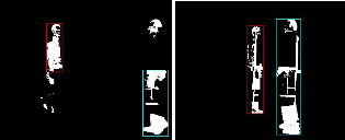
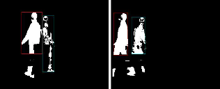
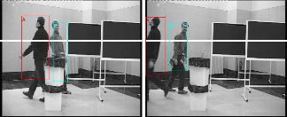
Fig no: 8 frames showing people separation correctly.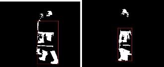
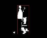
Fig no: 9 frames showing segmentation error.
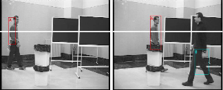
For counting people in the frame we have set the limit to 8. So that if 8 persons are moving at a time then we can represent them separately. Segmenting errors results in the counting error also. Correct frames showing the results are shown in Fig no: 10 and the error frames are shown in Fig no: 11.
Fig no: 10 frames showing tracked output with correct representation.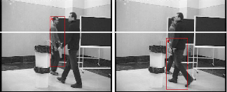
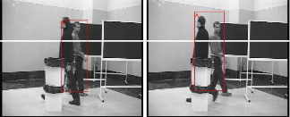
Fig no: 11 frames showing tracking error.
The authors would like to specially thank Mr.Gopalakrishnan, who is currently WORKING IN Keltron controls Vytilla for his guidance and suggestions to prepare this paper.
IJSER © 2013 http://www.ijser.org
International Journal of Scientific & Engineering Research, Volume 4, Issue 8, August-2013 1821
ISSN 2229-5518
[1] Optical Flow Estimation- David J. Fleet, Yair Weiss.
[2] Development of Human Tracking in Video Surveillance System for
Activity Analysis- Neelam V. Puri 1 and Prof. P. R. Devale
[3] C. Nakajima, M. Pontil, B. Heisele, and T. Poggio. People recognition in image sequences by supervised learning. In MIT AI Memo, 2000.
[4] A. Mittal and L.S. Davis. M2tracker: A multi-view approach to segmenting and tracking people in a cluttered scene using region-
based stereo. In Proc. 7th European Conf. Computer Vision, Kopenhagen, Danmark, volume X, pages 18– 33, 2002.
IJSER © 2013 http://www.ijser.org