International Journal of Scientific & Engineering Research Volume 2, Issue 4, April-2011 1
ISSN 2229-5518
Segmentation Techniques for Iris
Recognition System
Surjeet Singh, Kulbir Singh
Abstract— A biometric system provides automatic identification of an individual based on a unique feature or characteristic possessed by the individual. Iris recognition is regarded as the most reliable and accurat e biometric identification system available. Iris recognition systems capture an image of an individual's eye, the iris in the image is then segm ent ed and normalized for feature ext raction process. The performance of iris recognition systems highly depends on segment ation and normalization. This paper discusses the performance of segmentation techniques for iris recognition systems to increase the overall accuracy.
Index Terms—Active cont our, Biometrics, Daugman’s method, Hough Transform , Iris, Level Set method, Segmentation.
—————————— • ——————————
eliable personal recognition is critical to many processes. Nowadays, modern societies give higher relevance to systems that contribute to the increase of security and reliability, essentially due to terrorism and other extremism or illegal acts. In this context, the use of biometric systems has been increasingly encouraged by public and private entities in order to replace or improve traditional security systems. Basically, the aim is to establish an identity based on who the person is, rather than on what the person possesses or what the person
remembers.
Biometrics can be regarded as the automated
measurement and enumeration of biological
characteristics, in order to obtain a plausible quantitative value that, with high confidence, can distinguish between individuals.
Although less automatized, biometrics has
been used - at least - for centuries. In the 14th
century, the Portuguese writer Joa-o de Barros
reported its first known application. He wrote
that Chinese merchants stamped children’s palm
print and footprints on paper with identification
purposes. In the western world, until the late
1800s the automatic recognition of individuals
was largely done using “photographic memory”. In 1883, the French police and anthropologist Alphonse Bertillon developed an anthropometric
————————— ———————
• Kulbir Singh is currenty Assistant Professor, in Electronics &
Communication Engineering Department,Thapar University, Patiala,
India. E-mail: ksingh@thapar.edu
system, known as Bertillonage, to fix the problem of identification of convicted criminals.
In 1880, the British scientific journal Nature published an article by Henry Faulds and William James describing the uniqueness and permanence of fingerprints. This motivated the design of the first elementary fingerprint recognition system by Sir Francis Galton and improved by Sir Edward R. Henry. Having quickly disseminated, the first fingerprint system in the United States was inaugurated by the New York State Prison Department in 1903 and the first known convicted due to fingerprint evidences was reported in 1911.
Presently, due to increasing concerns associated with security and the war on terrorism, biometrics has considerably increased its relevance. It has moved from a single and almost standardized trait (fingerprint) to the use of more than ten distinct traits.
According to Matyas Jr. and Riha [1], every
biometric system depends on the features,
whether genotypic or phenotypic it is based on.
Similarly to Daugman [2], authors divide the
biometric traits into two types. Fried [3] and A. Bromba [4] classified the origin of the biometric traits into three different types: genotypic, behavioral, and randotypic.
Following the proposal of Jain et al. [5], biometric systems can be evaluated regarding
seven parameters: uniqueness, universality, permanence, collectability, performance, acceptability and circumvention.
Figure 2 contains a comparison between the
most common biometric traits. Each value was obtained through averaging and weighting of the classifications proposed in [6], [7], [4], [8], [9], [10] and [11].
For the purposes of our work, one of the most
important features is the ability to perform
IJSER © 2011 http://www.ijser.org
International Journal of Scientific & Engineering Research Volume 2, Issue 4, April-2011 2
ISSN 2229-5518
covert recognition, which can be performed by the fingerprint, face, iris and palmprint. Among these, iris must be enhanced, as it provides higher uniqueness and circumvention values.![]()
![]()
![]()
Genotypic Randotypic Behavioral

120%
100%
80%
60%
40%
20%
0%
Fig 1: Factors of influence of the biom etric traits.
during embryologic development. The collarette divides the iris into the pupillary zone, which encircles the pupil, and the ciliary zone, which extends from the collarette to the iris root. The colour of these two zones often differs [12].
The pupillary margin of the iris rests on the
anterior surface of the lens and, in profile, the iris
has a truncated cone shape such that the
pupillary margin lies anterior to its peripheral termination, the iris root. The root, approximately 0.5 mm thick, is the thinnest part of the iris and joins the iris to the anterior aspect of the ciliary body. The iris divides the anterior segment of the globe into anterior and posterior chambers, and the pupil allows the aqueous humor to flow from the posterior into the anterior chamber with no resistance.
120%
100%
80%
60%
40%
20%
0%

![]()
![]()
![]()
![]()
![]()
![]()
![]()
Uniqueness Universatilty Permanence Collectability Performance Acceptability Circumvention
Fig 2: Comparison between the most common biometric traits (adapted and averaged from [6], [7], [4], [8], [9], [10] and [11]).
The iris is a thin, circular structure located
anterior to the lens, often compared to a diaphragm of an optical system. The centre aperture, the pupil, actually is located slightly nasal and inferior to the iris centre. Pupil size regulates retinal illumination. The diameter can vary from 1 mm to 9 mm depending on lighting conditions. The pupil is very small (miotic) in brightly lit conditions and fairly large (mydriatic) in dim illumination. The average diameter of the iris is 12 mm, and its thickness varies. It is thickest in the region of the collarette, a circular ridge approximately 1.5 mm from the pupillary margin. This slightly raised jagged ridge was the attachment site for the fetal pupillary membrane
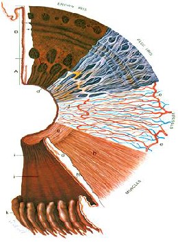
Fig 3: Surfaces and layers of the iris [12].
In figure 3 the iris cross-section shows the papillary (A) and ciliary portions (B), and the surface view shows a brown iris with its dense, matted anterior border layer. Circular contraction furrows are shown (arrows) in the ciliary portion of the iris. Fuchs’ crypts (c) are seen at either side of the collarette in the pupillary and ciliary portion and peripherally near the iris root. The pigment ruff is seen at the pupillary edge (d). The blue iris surface shows a less dense anterior border layer and more prominent trabeculae. The iris vessels are shown beginning at the major arterial circle in the ciliary body (e). Radial branches of the arteries and veins extend toward the pupillary region. The arteries form the incomplete minor arterial circle
IJSER © 2011 http ://www.ijser.org
International Journal of Scientific & Engineering Research Volume 2, Issue 4, April-2011 3
ISSN 2229-5518
(f), from which branches extend toward the pupil, forming capillary arcades. The sector below it demonstrates the circular arrangement of the sphincter muscle (g) and the radial processes of the dilator muscle (h). The posterior surface of the iris shows the radial contraction furrows (i) and the structural folds of Schwalbe (j). Circular contraction folds also are present in the ciliary portion. The pars plicata of the ciliary body is at (k). [13]
In this paper CASIA iris image database has been used for the analysis of different segmentation algorithms. CASIA iris image database (version 1.0) includes 756 iris images
Based on the assumption that the pixels’ intensity of the captured image can be well represented by a mixture of three Gaussian distributions, Kim et al. [28] proposed the use of Expectation Maximization [29] algorithm to estimate the respective distribution parameters. They expected that ‘Dark’, ‘Intermediate’ and
‘Bright’ distributions contain the pixels
corresponding to the pupil, iris and reflections areas.
This is by far the most cited method [14] in the iris recognition literature. The author assumes both pupil and iris with circular form and applies the following integrodifferential operator:
from 108 eyes, hence 108 classes.
In 1993, J. Daugman [14] presented one of the
![]()
maxr,xo,yo Gcr(r) *
r,xo,yo
![]()
I(x, y)
2rrr ds (1)
most relevant methods, constituting the basis of
the majority of the functioning systems.
Regarding the segmentation stage, this author
introduced an integrodifferential operator to find
both the iris inner and outer borders. This
operator remains actual and was proposed in
2004 with minor differences by Nishino and
Nayar [15].
Similarly, Camus and Wildes [16] and
Martin-Roche et al. [17] proposed integrodifferential operators that search the N3 space, with the objective of maximizing the equations that identify the iris borders.
Wildes [18] proposed iris segmentation through a gradient based binary edge-map construction followed by circular Hough
transform. This is the most common method, that has been proposed with minor variants by Cui et al. [19], Huang et al.[20], Kong and Zhang[21], Ma et al.[22], [23] and [24].
Liam et al. [25] proposed one interesting
method essentially due to its simplicity. This method is based in thresholds and in the maximization of a simple function, in order to obtain two ring parameters that correspond to iris inner and outer borders.
Du et al. [26] proposed the iris detection
method based on the prior pupil segmentation.
This operator searches over the image
domain (x, y)for the maximum in the blurred (by
a Gaussian Kernel Gcr(r) partial derivative with
respect to increasing radius r, of the normalized
contour integral of I(x, y) along a circular arc ds
of radius r and center coordinates (xO, yO ). In
other words, this method searches in the N3
space for the circumference center and radius with highest derivative values comparing to circumferences of neighbour radius.
At first the blurring factor a is set for a coarse
scale of analysis so that only the very
pronounced circular transition from iris to (white) sclera is detected. Then after this strong circular boundary is more precisely estimated, a second search begins within the confined central interior of the located iris for the fainter pupillary boundary, using a finer convolution scale a and a smaller search range defining the paths
(xO, yO , r)contour integration. In the initial search
for the outer bounds of the iris, the angular arc of
contour integration ds is restricted in range to
two opposing Ocones centered on the
horizontal meridian, since eyelids generally obscure the upper and lower limbus of the iris. Then in the subsequent interior search for the pupillary boundary, the arc of contour
integration ds in operator (1) is restricted to the
O
The image is further transformed into polar
upper 270
in order to avoid the corneal specular
coordinates and the iris outer border is detected
reflection that is usually superimposed in the
O
as the largest horizontal edge resultant from
lower 90
cone of the iris from the illuminator
Sobel filtering. However, this approach may fail
in case of non-concentric iris and pupil, as well as for very dark iris textures.
Morphologic operators were applied by Mira and Mayer [27] to obtain iris borders. They
detected the pupillary and scleric borders by applying thresholding, image opening and closing.
located below the video camera. Taking the
absolute value in (1) is not required when the
operator is used first to locate the outer
boundary of the iris, since the sclera is always
lighter than the iris and so the smoothed partial
derivative with increasing radius near the limbus
is always positive. However, the pupil is not
always darker than the iris, as in persons with
normal early cataract or significant back-
IJSER © 2011 http://www.ijser.org
International Journal of Scientific & Engineering Research Volume 2, Issue 4, April-2011 4
ISSN 2229-5518
scattered light from the lens and vitreous humor;
applying the absolute value in (1) makes the
operator a good circular edge-finder regardless
of such polarity-reversing conditions. With a
automatically tailored to the stage of search for
both the pupil and limbus, and by making it
correspondingly finer in successive iterations, the
operator defined in (1) has proven to be virtually
infallible in locating the visible inner and outer
annular boundaries of irises.
Wildes et al. [18], Kong and Zhang [21], Tisse et al. [30] and Ma et al. [22] use Hough transform to localize irises. The localization method, similar to Daugman's method, is also based on the first derivative of the image. In the proposed method by Wildes, an edge map of the image is first obtained by thresholding the magnitude of the image intensity gradient:
|VG(x, y) * I(x, y)| (3)
Where V=: (a;ax , a;ay) and G(x, y) =

1 -(x-xo)2+(y-yo)
![]()
![]()
2ncr2 e
2cr2
. G(x, y) is a Gaussian
smoothing function with scaling parameter a to
select the proper scale of edge analysis.
The edge map is then used in a voting process to
maximize the defined Hough transform for the
desired contour. Considering the obtained edge
points as (xj , yj ),j = 1,2,…, n, a Hough transform
can be written as:
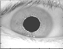
Fig 4: Segmentation by Daugman’s Method
For rapid discrete implementation of the
where
n
H(xc , yc , r) = h(xj , yj , xc , yc , r)
j=1
h(xj , yj , xc , yc , r) =
1 if g(xj, yj , xc , yc , r) = 0
0 otherwise
(4)
5)
integrodifferential operator in (1), it is more
The limbus and pupil are both modeled as circles
and the parametric function g is defined as:
efficient to interchange the order of convolution
and differentiation and to concatenate them,
2
g(xj , yj ,xc , yc , r) = (xj - xc )
2
+ (yj - yc )
before computing the discrete convolution of the resulting operator with the discrete series of undersampled sums of pixels along circular contours of increasing radius. Using the finite difference approximation to the derivative for a
discrete series in n,
- r 2 (6) Assuming a circle with the center (xc , yc ) and radius r, the edge points that are located over the
circle result in a zero value of the function. The
value of g is then transformed to 1 by the h
function, which represents the local pattern of
the contour. The local patterns are then used in a![]()
aGcr(r) �
ar
G1 (n)![]()
1![]()
= Lr Gcr(nLr)
Lr Gcr((n- 1)Lr) (2)
voting procedure using the Hough transform, H,
in order to locate the proper pupil and limbus
boundaries. In order to detect limbus, only
where Lr is a small increment in radius, and
replacing the convolution and contour integrals
with sums, we can derive through these manipulations an efficient discrete operator (3) for finding the inner and outer boundaries of an iris where L8 is the angular sampling interval along the circular arcs, over which the summed
I (x , y) pixel intensities represent the contour integrals expressed in (1).
Hough transform is a standard image analysis tool for finding curves that can be defined in a parametrical form such as lines, polynomials and circles. The recognition of a global pattern is achieved using the local patterns. For instance, recognition of a circle can be achieved by considering the strong edges in an image as the local patterns and searching for the maximum value of a circular Hough transform.
vertical edge information is used. The upper and
lower parts, which have the horizontal edge
information, are usually covered by the two
eyelids. The horizontal edge information is used
for detecting the upper and lower eyelids, which
are modeled as parabolic arcs.
We implemented this method in MATLAB® by first employing Canny edge detection to generate an edge map. Gradients were biased in the vertical direction for the outer iris/sclera boundary, as suggested by Wildes et al. [24]. Vertical and horizontal gradients were weighted equally for the inner iris/pupil boundary.
The range of radius values to search for was
set manually, depending on the database used.
For the CASIA database, values of the iris radius
range from 90 to 150 pixels, while the pupil radius ranges from 28 to 75 pixels. In order to make the circle detection process more efficient and accurate, the Hough transform for the
IJSER © 2011 http ://www.ijser.org
International Journal of Scientific & Engineering Research Volume 2, Issue 4, April-2011 5
ISSN 2229-5518
iris/sclera boundary was performed first, then the Hough transform for the iris/pupil boundary was performed within the iris region, instead of the whole eye region, since the pupil is always within the iris region.
up curve evolution. Note that, when the function
g is constant 1, the energy functional in (9) is the area of the region Q- = {(x, y) cp(x, y) < 0} . The energy functional Ag (cp) in (9) can be viewed as the weighted area of Q-. The coefficient v of A
can be positive or negative, depending on the
relative position of the initial contour to the
object of interest. For example, if the initial contours are placed outside the object, the coefficient v in the weighted area term should take positive value, so that the contours can shrink faster. If the initial contours are placed inside the object, the coefficient v should take negative value to speed up the expansion of the contours.
By calculus of variations , the Gateaux derivative (first variation) of the functional E in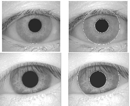
(10) can be written as
aE
![]()
![]()
= -11 Lcp - div
Vcp
Fig 5: Segmentation by Hough Transform.
acp
|Vcp|
In image segmentation, active contours are
Vcp
![]()
-A (cp)div(g - vg (cp) (11)
|Vcp|
where L is the Laplacian operator. Therefore, the
function cp that minimizes this functional satisfies
E
dynamic curves that moves toward the object
the Euler-Lagrange equation![]()
cp
= 0.The steepest
boundaries. To achieve this goal, we explicitly
define an external energy that can move the zero
descent process for minimization of the functional E is the following gradient flow:
level curve toward the object boundaries. Let I be
acp
Vcp
an image, and g be the edge indicator function
defined![]()
![]()
= 11 Lcp - div
at Vcp|
Vcp
![]()
1
g = (7)
-A (cp)div(g
|Vcp|![]()
- vg (cp) (12)
1 + |VGcr * I|2
where Gcr is the Gaussian kernel with standard
deviation a. We define an external energy for a
this gradient flow is the evolution equation of the
level set function in the proposed method.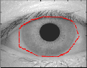
Left click to get iris points, right click to get end point
function cp(x, y) as below
Eg,A,v (cp) = ALg (cp) + vAg (cp) (8)
where A > 0 and v are constants, and the terms
Lg (cp) and Ag (cp) are defined by
50
100
150
200
50
100
150
200
Lg (cp) = g
n
(cp)|Vcp|dxdy
250
50 100 150 200 250 300
250
50 100 150 200 250 300
Ag (cp) = gH(-cp)dxdy
n
(9)
Left click to get pupil points, right click to get end point
50 50
respectively, where is the univariate Dirac
function, and H is the Heaviside function. Now,
we define the following total energy functional
E(cp) = 11P(cp) + Eg,A,v (cp) (10)
The external energy Eg,A,v drives the zero level set
toward the object boundaries, while the internal
energy 11P(cp) penalizes the deviation of cp from a
signed distance function during its evolution. To
understand the geometric meaning of the energy,
Lg (cp)we suppose that the zero level set of cp can
be represented by a differentiable parameterized
curve C(p), p E [0, 1]. It is well known that the energy functional Lg (cp)) computes the length of
100
150
200
250
50
100
150
200
250
50 100 150 200 250 300
50 100 150 200 250 300
100
150
200
250
50 100 150 200 250 300
the zero level curve of cp in the conformal metric
ds = g(C(p))IC'(p)Idp. The energy functional Ag (cp) in (3.24) is introduced to speed
Fig 6: (a) Selected iris m ask (b) iris/sclera boundary (c)
selected pupil mask (d) iris/pupil boundary (e) segment ed image (f) iris region.
IJSER © 2011 http ://www.ijser.org
International Journal of Scientific & Engineering Research Volume 2, Issue 4, April-2011 6
ISSN 2229-5518
The second and the third term in the right
hand side of (12) correspond to the gradient flows of the energy functional Lg (cp) and vAg (cp),
respectively, and are responsible of driving the
zero level curve towards the object boundaries. To explain the effect of the first term, which is
associated to the internal energy 11P(cp), we
notice that the gradient flow
Vcp
which could make the recognition process less accurate, since there is less iris information. However, this is preferred over including too much of the iris region, if there is a high chance it would also include undetected eyelash and eyelid regions.
Lcp - div
![]()
|Vcp|![]()
= div 1- 1
|Vcp|
Vcp (13)
![]()
has the factor 1- 1 as diffusion rate. If
|Vcp|
Vcp| > 1, the diffusion rate is positive and the
effect of this term is the usual diffusion, i.e.
making cp more even and therefore reduce the
gradient Vcp|. If Vcp| < 1, the term has effect of
reverse diffusion and therefore increase the
gradient [31].
The automatic segmentation model using
Integrodifferential equations and Hough transform proved to be successful. The CASIA database provided good segmentation, since those eye images had been taken specifically for iris recognition research and boundaries of iris pupil and sclera were clearly distinguished. For the CASIA database, the Hough transform based segmentation technique managed to correctly segment the iris region from 658 out of 756 eye images, which corresponds to a success rate of around 87% as compared to the Hough transform based segmentation technique that managed to correctly segment the iris region from 624 out of 756 eye images, which corresponds to a success rate of around 83%.
Using Integrodifferential equations and Hough transform methods on locating the pupil and limbus assume that the boundaries are perfect circles. Although the approaches are different, all these methods consider pupil and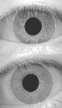
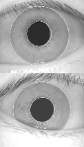
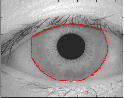
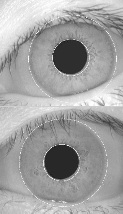
Fig 7: Illustrate the results of the Integrodifferential operat or over the pupils that are not perfect circles. The circular contour does not detect pupil boundaries accurat ely.
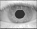
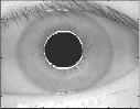
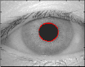
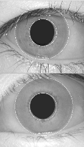
Fig 8: Illustrate the results of the Hough transform operator over the pupils that are not perfect circles. The circular cont our does not detect pupil boundaries accurately.
limbus as circular curves. It has been noticed that
the circular assumption of the contours can lead to inappropriate boundary detection Figure 7 and 8.
The above methods of segmentation resulted in false detection due to noises such as strong
boundaries of upper and lower eyelids. The strong eyelid boundaries and presence of eyelashes affected the limbus localization significantly.
We also implemented eyelashes and eyelids
detection for the above two methods. The eyelid detection system proved quite successful, and
50
100
150
200
250
50
100
150
200
250
50 100 150 200 250 300
50 100 150 200 250 300
50
100
150
200
250
50
100
150
200
250
50 100 150 200 250 300
50 100 150 200 250 300
managed to isolate most occluding eyelid regions. One problem was that it would sometimes isolate too much of the iris region,
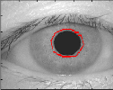
Fig 9: Illustrate the results of the active contour segmentation method based on Level set evolution without re-initialization over the pupils that are not perfect circles.
IJSER © 2011 http ://www.ijser.org
International Journal of Scientific & Engineering Research Volume 2, Issue 4, April-2011 7
ISSN 2229-5518
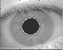
The eyelash detection system implemented for the CASIA database also proved to be successful in isolating most of the eyelashes occurring within the iris region as shown in Figure 11. A slight problem was that areas where the eyelashes were light, such as at the tips were not detected. However, these undetected areas were small when compared with the size of the iris region.
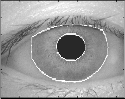
Fig 10: Automatic segmentation of image from CASIA
database. Black region denote det ected eyelid.
Fig 11: The eyelash detection technique, eyelash regions are det ected using thresholding and denot ed as black.
TABLE I
COMPARISON OF DIFFERENT SEGMENTATION
TECHNIQUES.
Method | No. Of eye images | Properly Segmented | Accuracy |
Daugman’s Method | 756 | 658 | 87% |
Hough Transform | 756 | 624 | 83% |
Proposed Method | 756 | 750 | Approx: 100% |
The proposed method of active contour segmentation based on Level set evolution without re-initialization provided perfect
segmentation results for the pupil and limbus boundaries with success rate of almost 100%. Only problem with this system was that the initial contour was to be defined for each eye image manually.
[1] V. Matyas and Z. Riha, “Toward reliable user authentication through biometrics,” IEEE Security and Privacy, vol. 1, no. 3, pp. 45–49, 2003.
[2] J. G. Daugman, “Phenotypic versus genotypic approaches
to face recognition,” Face Recognition: From Theory to
Applications, pp. 108–123. Heidelberg: Springer-Verlag,
1998.
[3] S. D. Fried, “Domain access control systems and methodology,”htt p://www.it u.dk/courses/SIAS/E2005/AU22
40 01.pdf , 2004.
[4] M. Bromba, Biometrics FAQ’s, http://www.bromba.com/faq/biofaqe.htm, 2010.
[5] A. K. Jain, R. Bolle, and S. Pankanti, Personal
Identification in networked society, 2nd edition. Kluwer
Academic Publisher, E.U.A., 1999.
[6] A. K. Jain, A.Ross, and S. Prabhakar, “An introduction to biometric recognition,” IEEE Transactions on Circuits and Systems for Video Technology, vol. 14, no. 1, pp. 4–19, January 2004.
[7] S. Liu and M. Silverman, “A practical guide to biometric security technology,” IT Professional, vol. 3, no 1, pp. 27–
32, January 2001.
[8] Biometrics and the courts, http://ctl.ncsc.dni.us/biomet%20web/BMIndex.html,
2010.
[9] Idesia’s Biometric Technologies. Biometric comparison table,http://www.idesia- biometrics.com/technology/biometric_comparison_table. ht ml, 2010.
[10] International Biometric Group, “Which is the best biometric technology?,” http://www.biometricgroup.com/reports/public/report s/best_biometric.html, 2010.
[11] J. D. Woodward, K. W. Webb, E. M. Newton, M. A.
Bradley, D. Rubenson, K. Larson, J. Lilly, K. Smythe, B. Houghton, H. A. Pincus, J. Schachter, and P. Steinberg, “Army Biometric Applications - Identifying and Addressing Socio-Cultural Concerns,” Rand Corporation, Santa Monica, 2001.
[12] A. K. Khurana, Comprehensive Ophthalmology, New
Age International (P) Ltd., 4th edition, 2007.
[13] L. A. Remington, Clinical Anatomy of the Visual System, Elsevier Inc., 2nd edition, 2005.
[14] J. G. Daugman, “High confidence visual recognition of persons by a test of statistical independence,” IEEE Transactions on Pattern Analysis and Machine Intelligence, vol. 25, no. 11, pp. 1148–1161, November
1993.
[15] K. Nishino and S. K. Nayar, “Eyes for relighting,” ACM Trans. Graph., vol 23, no. 3, pp. 704–711, 2004.
[16] T.A. Camus and R. Wildes, “Reliable and fast eye finding
in close-up images,” Proceedings of the IEEE 16th
IJSER © 2011 http://www.ijser.org
International Journal of Scientific & Engineering Research Volume 2, Issue 4, April-2011 8
ISSN 2229-5518
International Conference on Pattern Recognition, pp. 389–
394, Quebec, August 2002.
[17] D. Martin-Roche, C. Sanchez-Avila, and R. Sanchez- Reillo, “Iris recognition for biometric identification using dyadic wavelet transform zero-crossing,” IEEE Aerospace and Electronic Systems Magazine, Mag. 17, no. 10, pp. 3–
6, 2002.
[18] R. P. Wildes, “Iris recognition: an emerging biometric technology,” Proceedings of the IEEE, vol. 85, no.9, pp.
1348–1363, U.S.A., September 1997.
[19] J. Cui, Y. Wang, T. Tan, L. Ma, and Z. Sun, “A fast and robust iris localization method based on texture segmentation,” Proceedings of the SPIE Defense and Security Symposium, vol. 5404, pp. 401–408, August 2004.
[20] J. Huang, Y. Wang, T. Tan, and J. Cui, “A new iris segmentation method for recognition,” Proceedings of the
17th International Conference on Pattern Recognition
(ICPR), vol. 3, pp. 23–26, 2004.
[21] W. K. Kong and D. Zhang, “Accurate iris segmentation method based on novel reflection and eyelash detection model,” Proceedings of the International Symposium on Intelligent Multimedia, Video and Speech Processing, pp.
263–266, Hong Kong, May 2001.
[22] L. Ma, Y. Wang, and T. Tan, “Iris recognition using circular symmetric filters,” Proceedings of the 25th International Conference on Pattern Recognition, vol. 2, pp. 414–417, Quebec, August 2002.
[23] L. Ma, T. Tan, Y. Wang, and D. Zhang, “Personal
identification based on iris texture analysis,” IEEE Transactions on Pattern Analysis and Machine Intelligence, vol. 25, no. 12, pp. 2519–2533, December
2003.
[24] L. Ma, Y. Wang, and D. Zhang, “Efficient iris recognition by characterizing key local variations,” IEEE Transactions on Image Processing, vol. 13, no. 6, pp. 739–750, June
2004.
[25] L. Liam, A. Chekima, L. Fan, and J. Dargham, “Iris recognition using self organizing neural network,” Proceedings of the IEEE Student Conference on Research and Developing Systems, pp. 169–172, Malasya, June
2002.
[26] Y. Du, R. Ives, D. Etter, T. Welch, and C. Chang, “A new approach to iris pattern recognition,” Proceedings of the SPIE European Symposium on Optics/Photonics in Defence and Security, vol. 5612, pp. 104–116, October
2004.
[27] J. Mira and J. Mayer, “Image feature extraction for application of biometric identification of iris - a morphological approach,” Proceedings of the 16th Brazilian Symposium on Computer Graphics and Image Processing, pp. 391–398, Brazil, October 2003.
[28] J. Kim, S. Cho, and J. Choi, “Iris recognition using wavelet
features,” Kluwer Academic Publishers, Journal of VLSI Signal Processing, no. 38, pp. 147– 256, November 2004.
[29] A. P. Dempster, N. Laird, and D. Rubin, “Maximum
likelyhood from incomplete data via the EM algorithm,” Journal of the Royal Statistic Society, vol. 39, pp. 1–38,
1977.
[30] C. Tisse, L. Martin, L. Torres, and M. Robert, “Person identification technique using human iris recognition,”
Proceedings of the 25th International Conference on
Vision Interface, pp. 294–299, Calgary, July 2002.
[31] C. Li, C. Xu, C. Gui, and M. D. Fox, “Level Set Evolution Without Re-initialization: A New Variational Formulation,” IEEE Computer Society Conference on Computer Vision and Pattern Recognition, vol. 1, pp. 430
– 436, 2005.
IJSER © 2011 http://www.ijser.org