Using the formula; electric field intensity is given as;
E = P1 X 120π = 30 P1 = 30 p1
4πr r2 r
Where Pt = transmission power r = distance at point 1;
International Journal of Scientific & Engineering Research, Volume 4, Issue 4, April-2013 647
ISSN 2229-5518
ighawin@yahoo.com
This study aims at analyzing the pattern of interference that exists between the two neighbouring radio and television stations – the ITV Benin and the OSRC Akure. In this regard the poor television signal reception at Akure, Okitipupa, Owo all in Ondo state and Ewu, Ogua, Izakagbo all in Edo State are noted. Data collected through measurement and calculations (using the inverse square law model) verify the existence of interference due to adjacent channel signal propagation between the OSRC and ITV respectively.
ITV Benin is on channel 22 UHF (ultra-high frequency) while the OSRC Akure is on channel
23 UHF. Results of measurements taken show that the six mentioned towns experience more interference than others. Both signals tend to compete very highly in some areas and as such a phenomenon known as ghosting may appear. The effect of interference may cause one of the stations to go off air while the other may have very clear and good reception. The presence of buster stations was found to improve signals of the station it is boosting and as such no interference. The study further ends with measures for correction and reducing interference.
Keywords: channel, electric field strength, frequency, interference, magnetic field strength
IJSER © 2013
International Journal of Scientific & Engineering Research, Volume 4, Issue 4, April-2013 648
ISSN 2229-5518
The problems surrounding television (TV) broadcasting especially when it involves two or more close broadcast stations include interference, ghosting, cross-talk, poor picture quality, errors, poor frequency control, etc. These problems eventually create unpleasant situations which make television viewers have bad impressions and as such would want to find solutions. In most cases, some of the viewers are not able to find solutions especially if they are located in areas where strong effects of this phenomenon occur.
The term interference is said to occur when two waves that left one source and travelled by different paths arrive at a point and this occurs in micro wave space wave propagation [George K, Bernard D; 1999] this is one of the optical property of radio propagation. Optical effects as diffraction, refraction, reflection, and interference can alter the ray wave front propagation from the free space behaviour in the earth’s atmosphere. Radio frequency interference may be defined as an electromagnetic disturbance due to the super-imposition of an unwanted signal on a wanted signal hence producing a resultant having properties of both signals. Interference, can be produced when two or more signals
having similar properties (predominantly, frequency) join together, changing the amplitude or overall properties of the desired signal. Interference limits the performance of all communication system by restricting the operating range, generating error messages, and in extreme cases preventing the successful operation of receivers. Interference usually is destructive and corrupts the information [Bruce C; 2002].
Nigeria is among the few developing countries which have benefited from the growth of the telecommunication industry. As early as in the 50’s before her independence, in 1960
Nigeria was among the few foremost African countries to have the black and white television
IJSER © 2013
International Journal of Scientific & Engineering Research, Volume 4, Issue 4, April-2013 649
ISSN 2229-5518
as soon as it emerged in Europe and America. At the initial stage, TV broadcasting was a regional affair and band-width was acquired without regulation. As soon as the quest increased, the issue of interference started emerging. This led to the establishment of the National Broadcasting Commission (NBC) by the then military regime through the promulgation of decree no 38, later amended to decree no 55 of 1995. [Osita N; 1996]
The two stations under-study are the Ondo state radio-vision corporation (OSRC), Akure in Ondo State, and the Independent Television (ITV), Benin in Edo state. The OSRC transmits on channel 23 Ultra-High Frequency (UHF) while the ITV transmits on channel 22
UHF. OSRC in Ondo state is at Longitude 360 North and latitude with varying topography
that is irregular. The Ondo state TV station has three channels – 23, 25, and 27. Channels 25 and 27 are internally arranged to cater for the topography in a cardioids shape for effective radiation pattern. ITV Benin is in Edo state which is at Latitude 450 South. It is a private TV station. The two states have common geographical boundaries. Coincidentally they both operate on close frequencies hence the experience of interference in some towns in the two states. OSRC and ITV transmitters are air cooled. This enables the maintenance of low temperature for the equipment. OSRC Akure uses a 4-cavity Klystron with a voltage rating
of 2100 Vdc and a 2-cavity klystron made by town-send and Harris and its maximum power output of 40 KW. ITV Benin uses a pentode tube amplifier with an output power of 10KW [Gray M; 1993]. In Nigeria television broadcasting is assigned 8 MHZ at -6dB. This implies that at -20dB, W20 = 10.4 MHZ which is a substantial penetration into the adjacent channel.
The process of achieving the set objective(s) of this study comprises, using the inverse square law,
Collections of data from ITV and OSRC.
IJSER © 2013
International Journal of Scientific & Engineering Research, Volume 4, Issue 4, April-2013 650
ISSN 2229-5518
Investigation and measurement of the electromagnetic intensities at selected locations.
Investigation of adjacent channels interference between (ITV), Benin and OSRC Akure.
Evaluation of the strength of the adjacent channel interference.
Study of ways to reduce/eliminate this undesirable broadcast effect and
Validation of the quality of received signal
Different stations were visited and examined, their studios, news room, editing suites, transmitters and control rooms from each station. For the purpose of investigation, the following data or station parameters were collected for OSRC, Akure and ITV, Benin from respective stations.
From table 2.1, it is observed that the Nigerian Broadcasting Commission (NBC) licensed a transmitter output of 40KW for the Ondo state radio – Vision Corporation (OSRC), but the station transmit at 50% of the transmitter power output which is 20KW
ITV Benin | OSRC Akure | |
Data | UHF 22 | UHF 23 |
Channel number | 497.25 MHZ | 487.25MHZ |
Location | 05N40’06Z22 | 7N18’5E 12’ |
Transmitter output power | 10KW | 20KW |
Transmitter cooking method | Air Cooled | Water cooled |
Antenna gain | 30 dB | 30dB |
Antennas’ height above ground | 304.82m | 304.87m |
Type polarization | Horizontal | Horizontal |
IJSER © 2013
International Journal of Scientific & Engineering Research, Volume 4, Issue 4, April-2013 651
ISSN 2229-5518
Ground constant | 0.003(s/m) | 0.001(s/m) |
Number of cavity arrangement | 4 – cavity Klystron | 4 – cavity Klystron |
Transmitters manufacturers | Techno broadcast | Harris & town send |
. The towns and villages covered by the enclosure are; Ogwa, Iyanomo, Eguero, Izakagbo, Ose– river, Ugbokun, Ugbokun junction, Ekole, Igwige, Emah, Diomeye, Okohuo, Isiukhukhu. The signal strength was taken at different locations in most of the towns and villages mentioned with the aid of a field strength meter and the results of the exercise are shown in table 2.2.
Location of point | Video quality of station A(ITV) | Signal strength of station A(mV/m) | Distance of station A(Km) | Video quality of station B(OSRC) | Signal strength of station B (mV/m) | Distance of station B (Km) |
Ogwa | Excellent | 0.04 | 5.7 | Good audio and video | 0.013 | 22.20 |
Eguero | Excellent | 0.052 | 4.50 | Audio signal picked only | 0.003 | 23.40 |
Izaka-gho | Excellent | 0.10 | 5.20 | Only faint audio signal | 0.001 | 22.70 |
Igwiye | Fairly good | 0.05 | 8.10 | Better audio picked but faint video | 0.004 | 19.70 |
Ugbokun function | Fairly good as above | 0.04 | 7.10 | Better audio picked faint video | 0.02 | 20.70 |
Ugbokun town | Fair | 0.018 | 8,40 | Bad reception | 0.023 | 19.50 |
Okada | Fair video but good audio signals picked | 0.01 | 9.50 | Dodd audio faint video | 0.05 | 18.20 |
IJSER © 2013
International Journal of Scientific & Engineering Research, Volume 4, Issue 4, April-2013 652
ISSN 2229-5518
The line of sight (LOS) distance between OSRC and ITV is 111.20km apart. For convenience, this can be divided into ten equal parts and at the various distances, the field strength i.e. the signal field strength or electric field intensities can be calculated. The first field strengths at the first – five distances will be calculated, and shown while the other values will be imputed.
Since the line of sight (LOS) distance is 111.20km, we then have it to be 111200m and dividing into ten equal parts, we then have ten equal parts as;
Location | Distance (M) |
1 | 11120 |
2 | 22240 |
3 | 33360 |
4 | 44480 |
5 | 55600 |
6 | 66720 |
7 | 77840 |
8 | 88960 |
9 | 10080 |
10 | 111250 |
![]()
Using the formula; electric field intensity is given as;
E = P1 X 120π = 30 P1 = 30 p1
4πr r2 r![]()
Where Pt = transmission power r = distance at point 1;
E1 = p1 x 120π = 30p1
4 π r2 r1
IJSER © 2013
International Journal of Scientific & Engineering Research, Volume 4, Issue 4, April-2013 653
ISSN 2229-5518
ITV transmits from Iguosa Communication village, Edo State at
Pt = 10KW = 10 x 103 w![]()
E1 = 10 x 103 x 30 = 4.925562567 x 10⁻² (V/M) (1)
11120
At point 2;![]()
E2 = 10 x 103 x 30 = 2.462781284 x 10⁻² (V/M) (2)
22240
At point 3;![]()
E3 = 10 x 103 x 30 = 1.641854184 x 10⁻² (V/M) (3)
33360
At point 4;![]()
E4 = 10 x 103 x 30 = 1.231390642 x 10⁻² (V/M) (4)
44480
At point 5;![]()
E5 = 10 x 103 x 30 = 9.851125135 x 10⁻² (V/M) (5)
55600
Calculating for the remaining five points, the following table can be constructed as shown;
Location | Distance (m) | Electric field intensity (V/M) |
1 | 11120 | 0.049256 |
2 | 22240 | 0.024628 |
3 | 33360 | 0.016419 |
4 | 44480 | 0.012314 |
5 | 55600 | 0.009851 |
IJSER © 2013
International Journal of Scientific & Engineering Research, Volume 4, Issue 4, April-2013 654
ISSN 2229-5518
6 | 66720 | 0.008209 |
7 | 77840 | 0.007037 |
8 | 88960 | 0.006157 |
9 | 100080 | 0.005473 |
10 | 111200 | 0.004926 |
A graph of field strength is plotted against distances as shown in Fig 3.1
0.06
GRAPH OF ELECTRIC FIELD STRENGTH
0.05
0.04
0.03
0.02
0.01
0
0 20000 40000 60000 80000 100000 120000
Distance (m)
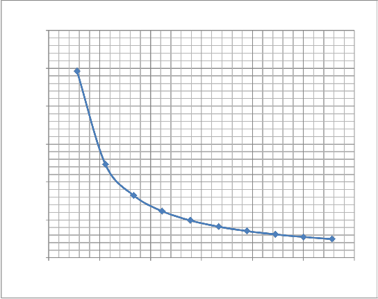
Fig. 3.1 Graph showing field strength from ITV Benin station to OSRC Akure
Calculating in similar manner as above OSRC has a maximum transmission power of 40KW but currently transmits at 20KW, 50 in computing for the field
strengths; we have that pt = 20KW Noting the distances, we inane at
IJSER © 2013
International Journal of Scientific & Engineering Research, Volume 4, Issue 4, April-2013 655
ISSN 2229-5518
Point 1;![]()
E1 = 30P1![]()
r1
Therefore E1 = 20 x 103 x 30 = 6.95797385 x10⁻² (V/M) (1)
11120
At point 2;![]()
E2 = 20 x 103 x 30 3.482898693 x 10⁻² (V/M) (2)
22240
At point 3;![]()
E3= 20 x 103 x 30 2.321932462 x 10⁻² (V/M) (3)
33360
At point 4;
![]()
E4= 20 x 103 x 30 1.741449346 x 10⁻² (V/M) (4)
44480
![]()
At point 5;
E5 = 20 x 103 x 30 1.393159477 x 10⁻² (V/M) (5)
55600
At point 6;
![]()
E6 = 20 x 103 x 30 1.160966231 x 10⁻² (V/M) (6)
66700
![]()
At point 7;
IJSER © 2013
International Journal of Scientific & Engineering Research, Volume 4, Issue 4, April-2013 656
ISSN 2229-5518
E7 = 20 x 103 x 30 9.951139122 x 10⁻² (V/M) (7)
77840
At point 8;
![]()
E8 = 20 x 103 x 30 x 10-2 (V/M) (8)
88960
At point 9;
![]()
E9 = 20 x 103 x 30 7.739774873 x 10⁻² (V/M) (9)
100080
![]()
At point 10;
E10 = 20 x 103 x 30 6.96579385 x 10⁻² (V/M) (10)
111200
From these calculations the table 3.3 shows the electric field strength as against distances is hereto indicated.
S/No | Distance (M) | Electric field intensity (V/M) |
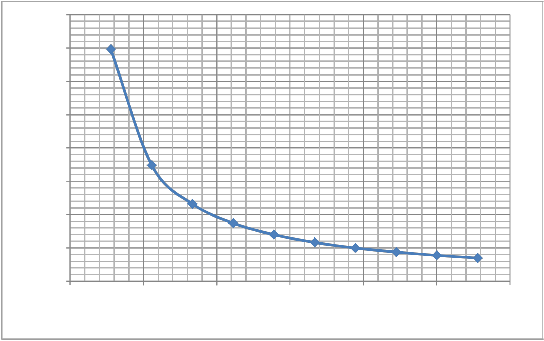
1 | 11120 | 0.069658 |
2 | 22240 | 0.034829 |
3 | 33360 | 0.023219 |
4 | 44480 | 0.017414 |
5 | 55600 | 0.013932 |
6 | 66720 | 0.011609 |
7 | 77840 | 0.009951 |
8 | 88960 | 0.008707 |
9 | 100080 | 0.007739 |
10 | 111200 | 0.006966 |
A graph of the electric field strength is plotted against distance as shown in Fig. 2.2
IJSER © 2013
International Journal of Scientific & Engineering Research, Volume 4, Issue 4, April-2013 657
ISSN 2229-5518
0.08
0.07
0.06
0.05
0.04
0.03
0.02
0.01
0
0 20000 40000 60000 80000 100000 120000
DISTANCE (m)
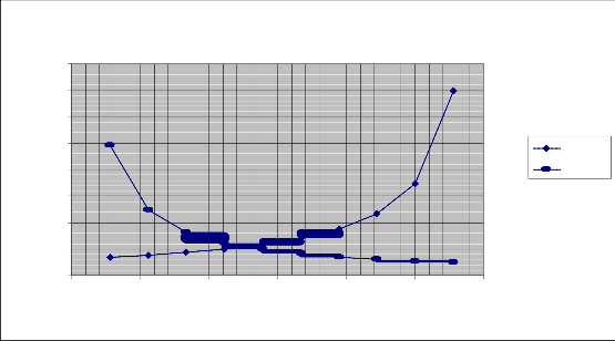
Fig. 3.2 Graph showing the field strength from OSRC to ITV Benin
The Intersection of the two graphs
0.08
0.07
0.06
0.05
0.04
0.03
Series1
Series2
0.02
0.01
0
0 20000 40000 60000 80000 100000 120000
Figure 3.3 Graph of interference of the two signals OSRC and ITV
IJSER © 2013
International Journal of Scientific & Engineering Research, Volume 4, Issue 4, April-2013 658
ISSN 2229-5518
From the calculated values of the signal strengths at the points from OSRC base station and ITV base station, the two graphs are then plotted on the same graph and this is done to enable us get the highest point at which the adjacent channel interference can be found, and from the graph the highest point of interference when traced down to the distance can be seen to be at about 4500m and 5600m. These are the areas where the reception of both signals seems to be unbearable as the signals both try to compete with each other and as a result, experiences known, sometimes a phenomenon known as ghosting may, also appear and in some other cases one of the station tends to gain the upper hand by having a stronger audio quality while the other, the video quality. Still interpreting from the graph, there are some locations where interference occurs but not greatly felt as the point mentioned earlier.
Furthermore, the graph then shows the reason why when watching programmers in any of the station; the other station tends to have a very clear and good reception. This is a clear phenomenon of what happens mainly in Ewu (on Ishan community in Edo State particularly, Idunwele), a similar situation occurs in some major towns in Akure like in Ore, Okitipupa etc. In addition, all the towns and villages in the enclosure in table 2.2 are areas that also suffer a great deal from the adjacent channel interference between ITV, Benin and OSRC, Akure.
The calculated values of the electric field strength at both stations has revealed that as one moves away from any of the transmitting station, the signal strength of the station concerned tends to be on the decrease. It can be seen that the point of interference occurs at a point of distance taken approximately to be at above 43.80km when moving from ITV
transmitter in Benin towards OSRC in Akure and at about 55.90km when moving from
IJSER © 2013
International Journal of Scientific & Engineering Research, Volume 4, Issue 4, April-2013 659
ISSN 2229-5518
OSRC, Akure towards ITV in Benin. From the graph, these two points are the main points at which interference can be felt or said to be at its highest point One of the solutions to the problem of co-channel interference was found to involve the use of offset carriers (22). It was found that if the picture carrier of one station’s signal was offset from the other station’s carrier, by one half the line frequency, the beat between carrier would then be a very fine pattern and the interfering signal would be of opposite polarity on odd and even lines, causing the interfering signal to become virtually unnoticeable at normal viewing distances. It was found, however, that in a situation where two or three stations were in close enough proximity to cause interference, a carrier offset of one half the line frequencies would be ineffective with respect to interference between two out of the three signals.
Road, New-Benin G.R.A, Ugbowo, Iguosa etc. | Areas, ITV signal strength dominate these towns as OSRC signal appears not to be observed in these areas. In this case, ITV happens to be in its main/coverage area while OSRC is in it’s fringe coverage area. |
Edo North (e.g. Ekpoma, Ewu, Ogwa etc. | The interference was observed to be minimum and disturbing. Both stations tends to gain upper hand in its signal strength, but ITV is on its secondary coverage area while OSRC on its fringe area. |
Central, South-West and South of Ondo State (e.g Ore, Ondo, Okitipupa etc.) | In Ondo, no sign of interference is observed, little interferences was noticed in some parts of Ore, while Okitipupa experienced some level of interference, but this was reduced due to the establishment of a booster station i.e OSRC Channel 27UHF, Ore Ondo Okitipupa are primary |
IJSER © 2013
International Journal of Scientific & Engineering Research, Volume 4, Issue 4, April-2013 660
ISSN 2229-5518

RECOMMENDATION
Coverage areas for OSRC but ITV
interferes at fringe coverage areas.
The Nigerian Broad casting commission (NBC) have a great role to play in commissioning this problem by making proper survey on a television station before allocating the channel and its frequency. A well informed and unbiased team of professionals should be sent to the proposed site where the new station is to be sited, then a well documented work should be done by the team by noting the following points - the geographical location where the new station is to sited, the antennal height for the proposed station, the antenna gain of the proposed station, the antenna orientation of the proposed station, the transmitter power of the proposed station, the transmitters and antenna location of the proposed station, the team should also make a proper investigation on the proposed site by noting if there are other television station on that geographical location operating; this is an important part of the survey to enable them detect if an already existing station in that particular area already has such a channel or frequency or a channel nearer to the proposed new station demanding for allocation. These details should then be fed back to NBC in order for them to do a well-detailed study of the geographical location before licensing and approving the channel allocation, antenna height, antenna gain, antenna orientation etc. for the proposed station.
Also NBC should make sure they enact a law to make sure that any licensed station should not transmit its signals beyond its seconding coverage area; this will be very useful because if the station transmits beyond its seconding coverage area, the signals may get to its fringe coverage area thereby causing interference with another station. But in a case where the station is allowed to transmit its signals beyond its secondary coverage area, then NBC
must, have done a good work in ensuring that the signals in the fringe coverage area should
IJSER © 2013
International Journal of Scientific & Engineering Research, Volume 4, Issue 4, April-2013 661
ISSN 2229-5518
not interfere with another station. In addition the installation of interference filters are advisable.
REFERENCES
edition, 1992
IJSER © 2013