International Journal of Scientific & Engineering Research, Volume 4, Issue 12, December-2013
ISSN 2229-5518
1677
SIMULATION & EXPERIMENTAL STUDY OF PARTIAL DISCHARGE IN INSULATING MATERIALS FOR HIGH VOLTAGE POWER EQUIPMENTS
Nidhi Singh1, Subhra Debdas2, Rajeev Chauhan3, Member, IEEE
nidhisinghjune@gmail.com1, subhra.debdas@gmail.com2, chauhanrajeev77@gmail.com3
Abstract— Insulators are the integral part of the high voltage power equipments, several types of insulators are used in high voltage electrical power system to protect the power equipments. For the purpose of safety and better efficiency, it is necessary to keep the insulators in a healthy condition during its operation. As the insulators are always in impure form due to presence of air bubbles (void) /other impurities inside the insulators, the local electrical breakdown is so called partial discharge (PD) takes place due to the high voltage stresses. Due to this, PD occurs and property of insulators deteriorates enormously. Therefore, detection of PD is the one of the important task for electrical engineers to
different insulating materials. Partial discharges within an insulating material are usually initiated within gas filled voids within the dielectric. Because the dielectric constant of the void is considerably less than the surrounding dielectric, the electric field (and the voltage stress) appearing across the void is significantly higher than across an equivalent distance of dielectric. If the voltage stress across the void is increased above the corona inception voltage (CIV) for the gas within the void, then PD activity will
start within void [1-5].
keep the high voltIage poJwer equipmSent in healthy ER
condition. In this paper an experimental and
simulation model study of both solid and liquid insulators has been done. Perspex as a solid insulator and oil as a liquid insulator are taken for realization of actual PD activity inside the insulators with the application of high voltages. Electrical equivalent model of the insulators has been developed using MATLAB Simulink environment with a cubical void (air bubble) as an impurity is taken inside the insulator. In this study, the maximum amplitude of PD, partial discharge pulses at different applied voltages, and amplitude of PD breakdown voltages with frequency are studied for the analysis of partial discharge characteristics in the insulating materials.
Keywords:- Insulators, Partial Discharge, High Voltage, Void, MATLAB Simulink etc.
1. INTRODUCTION
Partial Discharge (PD) generally begins within voids, cracks, at conductor-dielectric interfaces within a solid insulation system, or in bubbles within liquid dielectrics. Since discharges are limited to only a portion of the insulation, the discharges only partially bridge the distance between electrodes. PD can also occur along the boundary between
Once begun, PD causes progressive
deterioration of insulating materials, ultimately leading to electrical breakdown. PD can be prevented through careful design and material selection. In critical high voltage equipment, the integrity of the insulation is confirmed using PD detection equipment during the manufacturing stage as well as periodically through the equipment’s useful life using on- line partial discharge surveys. PD prevention and detection are essential to insure reliable, long-term operation of high voltage equipment. Error in such equipments causes in outgoing and many economical disadvantages. Many errors system that result in power system apparatus outgoing is related to insulation system and partial discharge that destroy the insulation gradually, in the most important fault resource in insulation of power system equipment [1-3]. Location techniques of this phenomenon are very important in maintenance and repair of equipments & many researches are already done in this domain [1-9]. Accurate modelling and simulating PD mechanism is the first stage for all PD localization studies. In most done
IJSER © 2013 http://www.ijser.org
International Journal of Scientific & Engineering Research, Volume 4, Issue 12, December-2013
ISSN 2229-5518
1678
researches, the simulations produced current impulses are used. But the mechanism of PD cannot be simulated in these researches. In this paper accurate mechanism of PD is simulated in MATLAB /Simulink software. The response of simulation are like as the results of laboratory experiments for the detection & analysis of PD.
2. PARTIAL DISCHARGE MECHANISM
According to IEC (International Electro Technical Commission) Standard 60270, Partial discharge is a localized electrical discharge that only partially bridges the insulation between conductors and which may or may not occur adjacent to a conductor [13]. In general partial discharges are a consequence of local electrical stress concentrations in insulation or on the surface of insulation. Such electrical discharges are
(b) Internal partial discharge
The partial discharge which is occurring inside of a system .The discharge in void is belonging to such type of partial discharge and necessary for PD measurement system. PD phenomena include several types of discharge which is surface discharge, cavity discharge, corona discharge, Treeing channel [2, 13].
Corona discharge: Corona discharge takes place due to non uniformity of electric field on sharp edges of conductor subjected to high voltage. The insulation supplied for such type of discharge is gas or air or liquid [2].
Surface discharge: Surface discharges takes place on interfaces of dielectric material such as gas/solid interface as gets over stressed times the stress on the solid material. This
IJSER
appeared as impulses i.e., various forms of
voltage impulse and current impulse having duration of much less than 1sec [5-13].
PD activity usually observed in high voltage power equipment like transformer, cable, bushings etc. PD usually begins within voids, cracks, or inclusions within a solid dielectric, at conductor-dielectric interfaces within solid or liquid dielectrics, or in bubbles within liquid dielectrics. Since discharges are limited to only a portion of the insulation, the discharges only partially bridge the distance between electrodes. PD can also occur along the boundary between different insulating materials.
2.1 CLASSIFICATION OF PARTIAL DISCHARGE
Partial discharge phenomenon is divided into two types
(a) External partial discharge
External partial discharge takes place outside of the power equipments .Such types of discharges occur in overhead lines, on armature etc.
may occur in bushing, end of cable, any
point on insulator surface between electrodes
(high voltage terminal & ground).
Treeing channel: High intensity fields are produced in an insulating material at its sharp edges and it deteriorates the insulating material .That is responsible for production of continuous partial discharge, called as Treeing channel.
Cavity discharge: The cavities are generally formed in solid or liquid insulating materials. The cavity is generally filled with gas or air. When the gas in the cavity is over stressed such discharges are taking place.
2.2 EFFECT OF A PARTIAL DISCHARGE IN INSULATING SYSTEM
Appearance of PD is the main reason for degradation of insulating material and responsible for happening of electrical breakdown. The occurrence of repetition rate of discharge is the reason for mechanical and chemical degradation of the insulating material. The effect of discharge on high voltage power equipment is severe to the insulation system. Insulation damage
IJSER © 2013 http://www.ijser.org
International Journal of Scientific & Engineering Research, Volume 4, Issue 12, December-2013
ISSN 2229-5518
1679
happens due to appearance of partial discharge (PD). The conductivity property of the insulating material rises due to chemical changes in the dielectric. Dielectrics are classified into several types like inorganic dielectric and organic dielectric. Generally immunity of inorganic dielectrics is more. Porcelain, glass, mica are belonging to such dielectric. Polymer dielectrics are belonging to organic dielectrics [1-15].
Generally, PD generates energy in the form of heat. Heat energy is the main reason for degradation of the insulation. This effect is known as thermal effect on insulating materials used. For high voltage power equipments, the deterioration of the insulation can be known by monitoring the PD activities. PD activity should be monitored time to time by the power engineer or power manager at the time of manufacturing [15-18].
Fig: 4 Measurement at a bushing taps
There are various methods are explored for the PD measurement based on both electrical and non electrical phenomena. The methods which have been popularly known for measurement of PDs are,
• Optical detection method
• Acoustic detection method
• Chemical detection method
• Electrical detection method
IJSER
2.3 PD DETECTION PRINCIPLES & METHODS
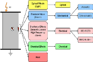
Fig: 2 Macroscopic-Physical Effects & Detection
Methods
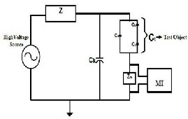
PD MEASURING CIRCUITS ACCORDING TO IEC 60270
Fig: 3 Frequently used circuit in test laboratories
2.3 FACTORS INFLUENCING THE DIELECTRIC STRENGTH OF INSULATING MATERIAL
It has been studied that some factors or conditions make effect on dielectric strength of insulating materials. The dielectric strength of insulating material depends upon temperature, impurity; spacing between electrodes etc. and some other factors are also responsible for it. In power equipments the strength of dielectric liquid used in high voltage transformer decreases to 70 % because of the impurity content like metal particles. Impurity includes solid particles like carbon, wax, and cellulose fiber acids. Impurity contents create imperfections in the insulation region [8-9-10].
3. NECESSITY OF DETECTION OF PARTIAL DISCHARGE (PD)
Most of insulators are in impure form. Due to presence of air impurity bubbles (void) are created within the insulating material. It weakens the insulation region and responsible for appearance of PDs. The reason behind it is, the dielectric constant of the void is less than of its surroundings. So it
IJSER © 2013 http://www.ijser.org
International Journal of Scientific & Engineering Research, Volume 4, Issue 12, December-2013
ISSN 2229-5518
1680
causes insulation failure in high voltage equipments. Partial discharges are always occurs at void, bad conductor profiles in HV equipments. Though such discharge has less magnitude but it is responsible for degradation. Due to occurrence of discharge ultimately failure occurs in the insulation system. Because of the above reason PD detection and measurement is necessary for prediction of insulation life for HV power equipments [10-15].
4. MODELING OF CIRCUIT FOR PD MEASUREMENT
The behaviour of internal discharges at AC voltage can be interpreted using the well known a-b-c model which is shown in fig.5. MATLAB SIMULINK model has been developed by calculating the various parameters required to design the a-b-c model for both the insulators Perspex and oil
5. EXPERIMENTAL SETUP & RESULTS
DDX 9101 partial discharge detector is used for the experimental study; this belongs to our very successful family of DDX detectors. It is the ideal solution for pass/fail partial discharge testing; incorporating all the basic functions of an analogue detector and meeting all IEC and IEEE/ANSI standards for PD testing. The DDX9101 simply measures the level of PD and the applied test voltage.
Once the voltage is applied to the test object, an indicator on the screen tells you if the test object passed or failed the test. All data is acquired during the test according to user- defined parameters, snapshot are taken of the ellipse at any time during a testing of the material. In this work experimental studies are conducted with two types of
[12-18].
configurations.
• Point – Plane Configurations
• Plane – Plane Configurations
Followings medium are taken in to account for this work.
1. Solid Insulator -Medium as Perspex.
2. Liquid insulator -Medium as Oil.
Case 1.Point – Plane Configurations
(a) Solid Insulator -Medium as Perspex
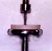
Fig. 5: Equivalent circuit & cylindrical void model inside solid dielectric
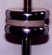
Fig. 6: Plane-Plane Electrode Sample with 8mm gap with Perspex as dielectric medium
IJSER © 2013 http://www.ijser.org
International Journal of Scientific & Engineering Research, Volume 4, Issue 12, December-2013
ISSN 2229-5518
1681
voltage for different insulating media both in solid & liquid resulting the breakdown into the insulating medium, Partial discharge characteristics of both medium can be analysed from the results obtained.
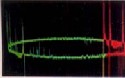
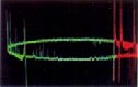
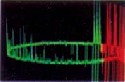
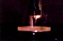
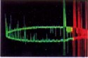
Table 1:-Measured Partial Discharge for Point – Plane Electrode Configuration for Perspex and oil
as an insulating material.
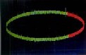
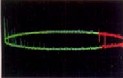
Fig. 7: Typical PD Pattern at V= 3 kV, 4 kV, 6kV, 7kV
Case 2 . Plane – Plane Configurations
8kV, 10kV & bIreakdowJn at 20kV foSr Perspex E(a) Solid RInsulator –Medium as Perspex
(b) Liquid Insulator -Medium as Oil
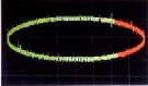
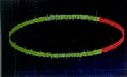
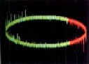
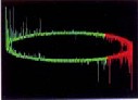
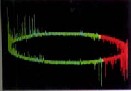
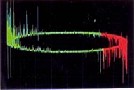
Fig. 8: Plane-Plane Electrode Sample with 8mm gap with Perspex as dielectric medium
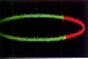
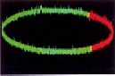
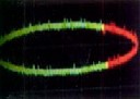
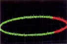
Fig. 8: Typical PD Pattern at V= 5 kV, 10 kV, 15kV,
20kV, 25kV, 30kV for Oil
The results are as shown in the table 1 & 2 from this it can be concluded that the PD increases with increase in applied high
IJSER © 2013 http://www.ijser.org
International Journal of Scientific & Engineering Research, Volume 4, Issue 12, December-2013
ISSN 2229-5518
1682
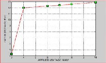
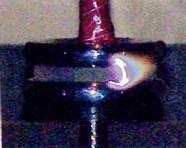
Fig. 9: Typical PD Pattern at V= 3kV, 5kV, 7kV, 12kV &
breakdown at 18kV for Perspex
(b) Liquid Insulator –Medium as Oil
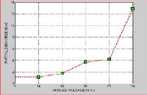
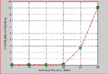
Fig.10: Partial Discharge in nC vs Applied voltage in kV for Solid Insulator –Perspex having dielectric constant 3.5 for Point - Plane Electrode Configuration
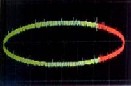
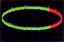
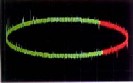
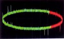
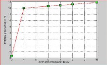
Fig.11: Partial Discharge in nC vs Applied voltage in kV for liquid Insulator –oil having dielectric constant 2.2-2.3 for Point - Plane Electrode Configuration
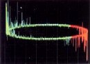
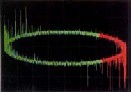
Fig. 9: Typical PD Pattern at V= 5 kV, 10 kV, 15kV,

20kV, 25kV, 30kV for Oil
Medium
Fig.12: Partial Discharge in nC vs Applied voltage in kV for Solid Insulator –Perspex having dielectric constant 3.5 for Point - Plane Electrode Configuration
kV Level
Perspex Oil
P.D Level (nC) P.D Level (nC)
3 1.16
5 1.17 1.08
7 1.18
10 1.08
12 1.20
15 1.08
18 B.D
20 1.14
25 3.67
30 10.1
Table 2:-Measured Partial Discharge for Plane – Plane Electrode Configuration for Perspex and oil
as an insulating material.
Fig.13: Partial Discharge in nC vs Applied voltage in kV for liquid Insulator –oil having dielectric constant 2.2-2.3 for Plane - Plane Electrode Configuration
IJSER © 2013 http://www.ijser.org
International Journal of Scientific & Engineering Research, Volume 4, Issue 12, December-2013
ISSN 2229-5518
1683
6. RESULTS & DICUSSION
The experimental results are formulated in tabular and graphical form for the partial discharge characteristics detection for both solid and liquid insulating material from the experimental setup using the DDX 9101 partial discharge detector & it is observed that when external high voltage applied through the separate source & amplitude of the partial discharges are higher & detected earlier in the solid insulator Perspex which is having the dielectric constant 3.5 and breakdown occurs earlier in both the configuration in the solid insulator than the liquid insulating oil which is having dielectric constant 2.2.
Similarly from the simulation results it is also observed that the amplitude of the partial discharges are more in the solid insulator and occurs at the low range of the
the oil. So it is concluded that the amplitude of partial are more in the solid insulating materials because of presence of air voids and others impurities rather than the liquid insulating mineral oil. Simultaneously MATLAB SIMULINK based model has been developed from the equivalent electrical model of an insulators to observe the characteristics of partial discharge activity inside the solid and liquid insulator at different applied voltage which arranges from 0-35 KV at constant power frequency (f=50 Hz). It is found that with the increase in applied voltage to the void present inside the insulation, partial discharge increases in Perspex which is having dielectric constant
3.5 the amplitude of partial discharge is more in Perspex in comparison to mineral oil which is having dielectric constant 2.2.
This work can also be extended in future for different high voltage power equipment
IJSER
applied high voltages.
Thus it is suggested that the partial discharges are more in the solid material than the liquid insulating material due to presence of the air void and others impurities. Thus on the basis of partial discharge characteristics oil is good insulating material than the solid material and can be used in high voltage equipment’s for specific application that is for low partial discharge requirements.
7. CONCLUSION & FUTURE SCOPE
Partial discharge is the main problem in high voltage power equipment system. Therefore, detection and measurement of partial discharge is necessary to keep the equipments in healthy condition during their operation. In this work experimental studies had been carried out for partial discharge measurement and detection using the DDX
9101 partial discharge detector. From the experimental studies it is observed that in each case the partial discharge detects earlier at the low values of applied high voltages and insulation break down occurs at low range of high voltage in case of Perspex than
model for detecting the PD activity. Further
the collected PD pulse can be processes with the help of FFT and Wavelet Transform and S- Transform for time frequency analysis for better study of PD measurement /detection.
8. REFERENCES
[1] G. C. Crichton, P. W. Karlsson and A. Pedersen, “Partial Discharges in Ellipsoidal and Spherical Voids”, IEEE Trans. on Dielectric and Electrical Insulation, Vol. 24, No. 2, pp. 335- 342, April 1989.
[2] R. J. Van Brunt, “Physics and Chemistry of partial discharges and corona”, IEEE Trans. on dielectric and Electrical Insulation, Vol. 1, No. 5, pp. 761-784, October 1994.
[3] A. A. Paithankar, A. D. Mokashi, “Can PD Phenomena be Analysed by Deterministic Chaos” EIC’97, Chicago, (IEEE) Conference preceedings, pp.
283-290, 1997.
[4] N. Kolev, P. Darjanov, E. Gadjeva and D. Darjanova, “Partial Discharge Phenomena Simulation using General-purpose Analysis Program”, Proc of
6th IEEE International Conference on Conduction and Breakdown in solid Dielectrics-ICSD 98, pp. 149-
152, June 22-25, Vasteras, Sweden, 1998.
[5] C. Y. Ren, Y. H. Cheng, P. Yan, Y. H. Sun, T. Shao, “Simulation of Partial Discharges in Single and
IJSER © 2013 http://www.ijser.org
International Journal of Scientific & Engineering Research, Volume 4, Issue 12, December-2013
ISSN 2229-5518
1684
Double voids Using SIMULINK”, Journal of Xi’an
Jiatong University, Vol. 38, No. 10, pp. 120-122,
2004.
[6] N. Kolev, P. Darjanov, E. Gadjeva and D. Darjanova, “An approach to develop a partial discharge investigation”, Proc. of the IEEE Electrical Insulation Conference and Electrical Manufacturing and Coil Windings conference, pp. 507-510, Chicago,
1997.
[7] L. Satish, and W. S. Zaengl, “Artificial Neural Networks for recognisation of 3D Partial Discharge patterns”, IEEE Trans. on Dielectrics and Electrical Insulation, Vol. 1, No. 2, pp. 265-275, April 1994.
[8] F. Gutleisch and L. Niemeyer, “Measurement and Simulation of PD in Epoxy Voids”, IEEE Transcation on Dielectrics and Electrical insulation, Vol. 2, No. 5, pp. 729-743, 1995.
[9] R. Bartnikas, “Partial Discharge their mechanism, Detection and Measurement”, IEEE Trans. Electr. Insul., Vol. 9, pp. 763-808, 2002.
[10] S. Karmakar, N. K. Roy, P. Kumbhakar, “Partial Discharge Measurement of Transformer
on C ondi t ion M o n itor in g and Diagnosis,
China, April 21-24, 2008.
[17] C. Forssén and H.Edin, “Partial Discharges in a Cavity at Variable Applied Frequency Part 1: Measurements”, IEEE Transactions on Dielectrics and Electrical Insulation, Vol. 15, No. 6,December
2008.
[18] R. E. James and B. T. Phung, “Development of Computer-based Measurements and their Application to PD Pattern Analysis”, IEEE Transactions on Dielectrics and Electrical Insulation, Vol. 2, No. 5, October 1995.
Nidhi Singh did her Bachelor Degree in Electrical Engineering and pursuing M.Tech. in Electrical Devices & Power Systems Engineering from Disha Institute of Management & Technology, Raipur, India. Her research interest is in High Voltage Power System.
S. Debdas was born in Naihati, West Bengal, India, on November, 1978. He graduated in Electrical
Engineering in 2001 from the Bengal Engineering
with ICT FacilitiesI”, ThirdJInternationaSl Conference ER
on Power Systems, Kharagpur, India, December27 -
29, 2009.
[11] S. Karmakar, N. K. Roy, P. Kumbhakar “Monitoring of high voltage power transformer Using direct Optical Partial Discharges detection technique”,journalofOptics,Vol.38,No. 4, pp.207-
215, 2009.
[12] E. Kuffel, W. S. Zaengl, J. Kuffel, High Voltage Engineering: Fundamentals, Published by Eleslever, ISBN 0-7506-3634-3, second edition,
2005.
[13] M. S. Naidu and V. Kamaraju, High Voltage
Engineering, New Delhi, Tata McGraw-Hill, pp. 69-
85, 2004.
[14] Mu Kuen Chen and C.Y.Cheng, “Proceedings of 2008 International Symposium on Electrical Insulating Materials”, September 7-11,Yokkaichi, Mie, Japan, 2008.
[15] T. Krüger and R. Patsch, “Active Noise Reduction for Partial Discharge Measurement in the Frequency Domain”, IEEE Bologna Power Tech Conference, Bologna, Italy, June23th- 26th, 2003.
[16] G. Chen and F. Baharudin, “Partial Discharge Modelling Based on a Cylindrical Mode in Solid D i el ect r i cs ”, I n t e r na t ion a l Confe r e n c e
College Shibpour, Howrah, West Bengal, India and
M.Tech in Electrical Power System from the Bengal Engineering and Science University Shibpour, Howrah, West Bengal, India. His special field of research includes power quality, harmonic detection and real time condition monitoring system. Now he is working as Associate Professor in Disha Institute of Management and Technology, Raipur, India. Mr. S. Debdas became a Sr. Member of IACSIT (China) & IAENG.
Rajeev Chauhan completed his B.E., M.Tech. & presently pursuing Ph.D form Birla institute of Technology, Mesra, Ranchi, India with the specialization in Power System. He is working as an Assistant Professor in Electrical Engineering Department at Gyan Ganga Institute of Technology & Science, Jabalpur, (M.P.), India. Rajeev Chauhan is a Member of IEEE & has teaching & industrial experience of more than 13 years. He was the Consultant Engg. with D.H.V. International, Netherland, Europe for various projects in India and abroad from 2000 to 2004. His expertise fields of interest are Power System Analysis & Control, Electrical Power Distribution System Planning and High Voltage Engineering.
IJSER © 2013 http://www.ijser.org