showed that the influence of rotation causes a destabilization of laminar flow at a critical reynolds number of 83. Velocity
International Journal of Scientific & Engineering Research, Volume 5, Issue 7, July-2014 360
ISSN 2229-5518
Reynolds Number Dependence on Laminar Flow in the Developing Region of a Rotating Pipe
Ojo Anthony O., Odunfa Kamilu M., and Oyewola Miracle O.
—————————— ——————————
he velocity and pressure profiles of a flow in a rotating pipe differs from that which is obtainable in a stationary pipe, as flow entering an axially rotating circular pipe is given a tangential velocity component by the moving pipe wall. Typ- ically, for a non rotating pipe, the tangential velocity equals zero. Laminar flow in a non rotating pipe is characterized by the poiseuille parabolic solution, where, so as to drive the flow against the resisting pipe wall shear stress, the pressure must decrease in the flow direction and as such, the resulting veloci- ty profile must have a negative curvature everywhere with maximum velocity occuring at the centreline. A flow entering an axially rotating pipe experiences flow instability and dis- turbance even at Reynolds number less than 2000[1] thereby resulting in a swirl flow. This study is concerned with flow in an axially rotating pipe, which finds application in engineer- ing practice, as it is obvious for example, in rotating heat ex- changers, in cooling systems of rotors and in the design of the cooling channels inside the rotating blades of gas turbines. Furthermore, these rotating flows also occurs in the inlet parts of fluid machines and of some pipe flow systems in a rotating
frame such as those on a spinning satellite.
The problem for swirl flows has been a subject of interest over the years and has been extensively studied via experi- mentation, analytical and numerical methods. Velocity profiles
————————————————
• OYEWOLA Miracle Olanrewaju (Ph.D) and ODUNFA Kamilu Mora-
deyo (Ph.D) are currently Lecturing at the department of Mechanical En- gineering in University of Ibadan, Nigeria. +2348039288464. E-mail:
mo.oyewola@ui.edu.ng ; +2348056130144. E-mail:m.odunfa@ui.edu.ng
in the developing flow region of a rotating pipe for and in- stance of very low Reynolds number, were analysed by Lavan et al.[2] and anaylsis of Pedly[3] and experimental procedure of Nagib et al [4] reveals that at fairly low Reynolds number, there is destabilization of laminar flow due to pipe rotation. Torii et al [5] investigated the secondary flow phenomena in an axially rotating flow passage with sudden expansion or contraction and emphasis was placed on Reynolds number and rotation rate on the formation of secondary flows. Alt- hough, restricted to small pipe rotation rates, the laminar flow inlet length was calculated by Mizutani et al.[6]. In particular, Yamada et al. [7] observed that when the laminar flow enters the axially rotating pipe, a destabilization of the flow due to the swirl is induced, resulting in an enhancement in the turbu- lence intensity. Lei et al. [8], through an experimental ap- proach, studied velocity measurements in four(4) different flow regimes of the laminar flow through a rotating straight pipe. Imao et al [9] compared numerical results of velocity profiles for laminar flow in the developing region of an axially rotating pipe with experimental results obtained when a uni- form axial flow is introduced with interest in flows where swirl component is large to produce flow reversal near the wall. Ayinde [10] showed that swirl decays downstream a pipe and established a generalized relationship for swirl decay as function of swirl number at inlet, Reynolds number, distance from pipe inlet, pipe diameter and nature of inlet swirl by us- ing a curve-fitting technique.
This present study is concerned with capturing the de-
pendence of Reynolds number variation (using very low Reynolds numbers) on the flow in a rotating pipe. This is mo- tivated by the availability and versatility of the commercial CFD modeling tool, comsol multiphysics in numerically simu-
IJSER © 2014 http://www.ijser.org
International Journal of Scientific & Engineering Research, Volume 5, Issue 7, July-2014 361
ISSN 2229-5518
lating laminar flow in a straight axially rotating pipe. The
choice of low Reynolds number is at par with Pedly[3] who
showed that the influence of rotation causes a destabilization of laminar flow at a critical reynolds number of 83. Velocity![]()
![]()
![]()
∂U + ∂V + V = 0
∂x ∂r r
(1)
profiles at two sections in the laminar entrance length of an axially rotating pipe section are analyzed at a specific pipe Reynolds number and with varying rotation speed.
x-direction (representing axial coordinate z):
∂U ∂U
1 ∂P
∂ 2U
∂ 2U
1 ∂U
NOMENCLATURE
D = Pipe Diameter (m)
R = pipe radius (m) = D/2![]()
U + V
∂x
![]()
![]()
= −
∂r r ∂x
![]()
+ ν
∂x 2
![]()
+
∂r 2
![]()
+
r ∂r
(2)
r = radial cordinate x = z = axial coordinate
U = axial velocity component (m/s)
r-direction:
∂V
∂V V 2
1 ∂P
∂ 2V
∂ 2V
1 ∂V V
V = radial velocity component (m/s)![]()
![]()
![]()
U + V −
∂x ∂r r
![]()
![]()
![]()
![]()
![]()
= − + ν + + −
r ∂r ∂x 2 ∂r 2 r ∂r r 2
(3)
W = tangential velocity component (m/s) Um = mean axial velocity at inlet (m/s)
Ww = tangential speed of pipe wall (m/s)
Ө-direction:
∂W
∂W VW
∂ 2W
∂ 2W
1 ∂W
W
(4)
N = rotation rate = Ww/U m
Rez = axial Reynolds number = DUm /2![]()
U + V
∂x
![]()
![]()
+
∂r r
![]()
= ν
∂x 2
![]()
+
∂r 2
![]()
+ −
r ∂r r
Greek Letters
ω = angular velocity
In the axially rotating pipe, the boundary conditions are speci-
fied as:
r = density (kg/m3)
υ = kinematic viscosity (m2/s)
U = V = 0,
W = WW
at wall
U = U in ,
V = W = 0 at the inlet.i.e: x= 0
Subscript
m = mean w = wall
Consider an incompressible fluid flowing in a pipe with a ra- dius R, which is axially rotating about the axis at constant an- gular velocity,![]() , the configuration and cylindrical coordinate system of the flow is shown in figure 1.
, the configuration and cylindrical coordinate system of the flow is shown in figure 1.
Fig. 1.The cylindrical coordinates: (a) Section of the pipe showing the axial coordinate z; (b) Cross-section AA showing r and Ө co- ordinates
The governing differential equations for mass and momentum are expressed as![]()
∂U = 0 , V = W = 0 at center(r = 0)
∂r
Kikuyama et al. [11] found that neither Reynolds number nor
rotation rate affects the radial profiles of the time-averaged tangential velocity at different axial locations. Torii et al showed that the rotating fluid moves as a rigid body. These governing equations can be discretized and solved using the finite difference approach, but the primary objective of this paper is to employ the use of comsol multiphysics, by selec- tion of relevant coordinates, appropriate geometry/domain and applying relevant boundary conditions, to flow in axially rotating pipe problems and then, analyze the ensuing results and compare with prior numerical and experimental investi- gations.
A numerical method is employed to determine velocity pro- files that result at varying Reynolds number and pipe rotation. At present, there is no available simulation data using comsol to the authors’ knowledge, which is pertinent to flow charac- teristics such as the velocity distribution for the axially rotat- ing pipe flow case. The swirling flow is two dimensions even though the model includes all three velocity components, U, V and W. Comsol Multiphysics Version 4.0a was employed for simulating the swirl flow which result from flow in an axially rotating pipe. For simplicity of modeling, especially in facili-
IJSER © 2014 http://www.ijser.org
International Journal of Scientific & Engineering Research, Volume 5, Issue 7, July-2014 362
ISSN 2229-5518
tating the rotation concept of the model, only one-half of the pipe cross-section (figure 2) is treated because of the symmetry in the fluid flow, this also helps to minimize calculation time. The domain of interest is discretized and the meshing used consists of 1956 elements with a refined mesh near the wall (figure 3). Comsol version 4.0a runs the Finite Element Meth- od (FEM) for discretisation of the domain and solving all equations inside. The use of FEM allows momentum conserva- tion in the domain; therefore ‘numerical loss’ of momentum in the computational domain is not a concern here and as such, this enables investigation of other parameters that pertain to the flow.
Fig. 2. Boundary settings for domain
Fig. 3. Mesh used for the axisymmetric domain- 1956 elements
flow at a Reynolds number of 40, hence, the boundary condi- tion employed at the entrance and the exit is accepted reason- able. A short pipe section is used to capture the flow in the developing region. The maximum entrance length within which the laminar flow is developing based upon the maxi- mum Reynolds number employed in this investigation is 3.6. Hence, the choice of the domain geometry is also acceptable. The pressure gradient at different section downstream away from the inlet is constant.
In this section, governing model equations and boundary
condition which are implemented in simulation software as well as result of simulation have been discussed. With the in- troduction of swirl, the flow ceases being smooth and steady (laminar) and becomes fluctuating and agitated (turbulent) as a transition to turbulence occurs due to flow disturbance by the rotating pipe wall. This swirl also causes a disturbance of the fully developed (poiseuile) velocity distribution downstream the pipe entrance. A uniform entry flow is assumed by the inlet boundary condition specified using the solver. The ex- tracted data from the model is subjected to the boundary con- ditions at the wall for axial and radial velocity and at the pipe center for tagential and radial velocity. Analysis of the velocity profiles at varying Reynolds number and pipe rotation rate for the reference point z = 0, at the pipe inlet is choosen to be compared with velocity profiles at a downstream section, z =
0.2, near the inlet.
For each of the Reynolds number employed, at z = 0, the entry velocity is constant (uniform) throughout the pipe radi- us and it is not influenced by the rate of pipe rotation as obivous in figure 4. The same is found to be true for axial ve- locity for all Reynolds number at z = 0. It is quickly seen from the same figure that flow reversal does not occur at the pipe entrance because of the boundary condition adopted but is obvious at downstream section, z = 0.2 at higher rotation rates. The tangential velocity and radial velocities at the pipe en- trance, z = 0, is zero for all Reynolds number and rotation rate. Figure 5 and figure 6 are applicable to all other Reynolds number considered. No difference in the tangential and radial velocity profile is observed at the pipe entrance for all rotation rates. Velocity profiles for the axial, tangential and radial ve- locities are different at z = 0.2 and at varying rotation rates. For each Reynolds number employed, the axial velocity increases downstream the pipe thereby approaching a parabolic profile and for larger Reynolds number, the approach of similar pro- file takes place further downstream the pipe but is altered by increasing N.
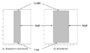
By means of a short pipe section, in order to establish the ra- tionality of this analysis with respect to utilizing the axisym- metric model case on comsol, flow using the properties of wa- ter for an incompressible flow in a stationary pipe, considering a non axisymmetric case – full domain in the solver is modeled and then, flow in a stationary pipe for an axisymmetric – half domain is considered. The resulting velocity profile at varying downstream sections of the pipe is analyzed. No significant differences are seen in the resulting profile and values for this
IJSER © 2014 http://www.ijser.org
International Journal of Scientific & Engineering Research, Volume 5, Issue 7, July-2014 363
ISSN 2229-5518
Fig. 4. Axial velocity at z = 0 – pipe inlet for Rotation
Rates; N= 0, 2, 4, 6
Fig. 5. Tangential velocity at z = 0 – pipe inlet for
Rotation Rates N= 0, 2, 4, 6
Fig. 6. Radial velocity at z = 0 – pipe inlet for Rotation
Rates N= 0, 2, 4, 6
The effect of pipe rotation on velocity profiles is investigat- ed at varying Reynolds numbers, 20, 30, 40, 50 and 60 and ro- tation rate (N=0, 2, 4, 6) at the downstream cross-section, z =
0.2 of a pipe being modelled. When laminar flow is introduced into an axially rotating pipe an adverse or large pressure gra-
dient in the axial direction as a result of swirl or pipe rotation causes a flow reversal near the pipe wall at a section near the inlet. The pressure gradient at the pipe inlet for a rotating pipe is much larger than for a stationary pipe because of the swirl given to the flow by the rotating pipe wall and this increase further with increase in rotation rate. At z = 0.2, as for other downstream sections, the axial velocity increases towards the pipe center and decrease close to the wall as a result of friction at the wall. The viscous boundary layers grow downstream, slowing down the axial flow at the wall and in this manner accelerating the center-core flow.
For each of the Reynolds number considered, increase in
the rotation rate results in an increase in axial velocity, U, at the center. No significant changes is noticed for the axial veloc- ity profile for N = 0 and N = 2 at z = 0.2, because the swirl in- troduced is small at low rotation rates. At the pipe centre the influence of increasing pipe rotation at each Reynolds number employed shows an increasing axial velocity for the flow. Thus pipe rotation causes increased center-core flow compared to stationary pipe flow.
The axial velocity is maximum near the wall at z = 0.2 and
upon increase in rotation rate and also increase in Reynolds
number (figure 7) this phenomenon becomes more pro- nounced. This is traceable to the large vorticity effect at occurs at that section. For N = 0, a stationary pipe case, the maximum axial velocity occurs close to the wall as a result of viscous ef- fect but the ensuing visous boundary layer grows downstream the pipe and retards the axial velocity at the wall resulting in a parabolic axial velocity profile further downstream upon the merging of the boundary layer. At z = 0.2, an investigation of the vorticity field shows a large vorticity effect at this down- stream section and as Reynolds number increases, there is an increase in vorticity in the axial direction.
With increasing rotation rate, the velocity profile changes
with the maximum axial velocity for each considered Reyn- olds number shifting away from the wall. This becomes signif- icant at N = 6 owing to the flow reversal occurring at this sec- tion for Reynolds Numbers, 30, 40, 50 and 60. With an increase in Reynolds number, it is seen that the flow reversal becomes significant for the downstream section considered as a result of the large pressure gradient. The backflow near the wall also increases with increase in rotation rate and this trend also in- creases with increase in Reynolds number as the pressure gra- dient becomes significantly increased under the influence of pipe rotation.This suggests that an increase pipe rotation in- fluences the tendency for flow reversal occurring at down- stream sections along a pipe wall away from the inlet and this becomes significant upon increase in the rotation rate which means the downstream section for which the flow becomes developed also increases.
It can be quickly seen from figure 7d that at N = 6 and for
Reynolds number 20, the backflow recorded very small at z =
0.2. At this low Reynolds number, the influence of rotation has
IJSER © 2014 http://www.ijser.org
International Journal of Scientific & Engineering Research, Volume 5, Issue 7, July-2014 364
ISSN 2229-5518
little effect on the flow because the fluid exhibits a high vis- cous creeping motion where inertia effects are negligible.
(d) N = 6
Fig. 7. Axial velocity at z = 0.2
(a) N = 0
(b) N = 2
(c) N = 4
The swirl component at the pipe inlet is large for a rotating
pipe and a tangential component is given to the flow by the rotating pipe wall. For N = 0, a non rotating pipe case and for all Reynolds number the tangential velocity is zero. The tan- gential velocity, W, of the fluid equals the tangential speed of the wall. There is a gradual decrease of the tangential velocity from the wall to it having a value of zero in the pipe center. This is as a result of the shear imposed on the fluid by the moving pipe wall. For low Reynolds number, increased rota- tion rate causes a large flow displacement. Owing to the low Reynolds number employed, and the nature of the flow mo- tion, for each rotation rate, the shear rate for Reynolds number of 20 is small and gradually increases as the Reynolds number increases.
With increasing rotation rate comes increasing shear rates.
Hence the tangential velocity profile (figure 8(a)~(c)) for reyn-
olds number 20 approaches a linear profile with increasing rotation rates. Since the shear rate is higher at higher reynolds number, the fluid close to the wall experiences deformation easily. This trend is amplified with increasing rotation rate. The rate of shear at this section (z = 0.2) is also higher due to the imposed swirl but decreases downstream the pipe. The decrease of shear rate downstream the pipe, upon an increase in rotation rate influences the tendency of the flow to a forced vortex type downstream the pipe [12].
IJSER © 2014 http://www.ijser.org
International Journal of Scientific & Engineering Research, Volume 5, Issue 7, July-2014 365
ISSN 2229-5518
(a) N = 2
(b) N = 4
(c) N = 6
Fig. 8. Tangential velocity at z = 0.2
ber is small and at larger Reynolds number, the radial velocity is small. It is observed that the minimum radial velocity occurs close to the wall.
The radial velocity is small for N = 0 and upon the intro-
duction of swirl, the radial velocity increases indicating dis- placement of fluid. The increasing rotation rate has a similar effect as increasing Reynolds number in terms of the radial velocity becoming small as the parameters are increased at the downstream section close to the pipe entrance. The Radial velocity decreases with increasing rotation speed. It can be quickly seen from figures 7 and 9 that the radial distance where maximum axial velocity is recorded is approximately the same as where the minimum radial velocity occurs for the same downstream section, Reynolds number and rotation rate.
(a) N = 0
(b) N = 2
The radial velocity becomes smaller as the rotation rate in-
creases for the region close to the pipe entrance (z = 0.2) and is negative everywhere. The radial velocity is negative every- where for N = 0,2,4 and 6 and all Reynolds number considered and with increase in Reynolds number, it is quickly seen from figure 9 that the radial velocity is large when Reynolds num-
IJSER © 2014 http://www.ijser.org
International Journal of Scientific & Engineering Research, Volume 5, Issue 7, July-2014 366
ISSN 2229-5518
(c) N = 4
(d) N = 6
Fig. 9. Radial velocity at z = 0.2
Numerical simulation using comsol multiphysics has been performed to compute the flow in an axially rotating pipe. Velocity profiles at different downstream sections have been analyzed and the influence of increasing Reynolds number and increasing rotation rates have been investigated with re- spect to the distribution of the axial, tangential and radial ve- locity of the flow.
Low Reynolds number was employed and the following conclusions can be drawn.
i. When laminar flow passes through an axially rotating pipe, flow reversal occurs downstream but near the pipe entrance and this trend is amplified with in- crease in rotation rate and Reynolds number. Down- stream the pipe, the axial velocity approaches a para- bolic profile and increases in the center with increased rotation rate and Reynolds number.
ii. Owing to the high swirl at the vicinity of pipe en- trance, the rate of shear for low Reynolds number is small and increases with rotation rate. With increas- ing Reynolds number, this rate of shear becomes large and this increases the tendency of the fluid to ap- proach a forced vortex type further downstream the pipe.
iii. The tangential velocity increases with increase in Reynolds number at the same rotation rate. As the Reynolds number decreases, the rate of rotation that the pipe can be subjected to reduces so as to yield a stable and converged solution. At low Reynolds number higher rotation rate are possible.
[1] Yamada, Y and Imao, S., 1980. Swirling flow in an axially rotating pipe. Trans. Japan of Mechanical Engineers,(in Japanese), Vol. 46, No.409, P.1662
[2] Lavan, Z., Nielsen, H., and Fejer A.A., 1969. Separation
and flow reversal in swirling flows in circular ducts. Phys. Fluids, Vol. 12, No 9, p1747
[3] Pedly, T.J, 1969. On the stability of viscous flow in a rap- idly rotating pipe, J. Fluid Mech., vol. 35.No.1,p. 97
[4] Najib, H. M., Wolf, L., Lavan, Z. and Feger, A.A, 1969.
On the Stability of the Flow in Rotating Pipes. Aerospace
Research Laboratories Report, No.69-9176. P.1
[5] Torii, S and Yang, W.J, 1999, Secondary flow phenomena in an axially rotating flow passage with sudden expan- sion or contraction. International Journal of Rotating Ma- chinery, 1999, Vol. 5 No 2, pp,117-122
[6] Mizutani, M., Nishibori, K., Kikuyama, K and Murakami,
M., 1987. Inlet Length for Laminar flow in an axially ro- tating pipe. Turbomachinery, vol. 15 No.3, p33
[7] Yamada, Y and Imao, S., 1985. Turbulence and its struc-
ture of the flow in an axially rotating pipe. Trans. Japan of Mechanical Engineers, (in Japanese), Vol. 51, No.461, P.34
[8] Lei U., Lin M. J., Sheen., H.J and Lin C. M., 1994. Velocity
measurements of the Laminar flow through a rotating
straight pipe, Phys. Fluids, vol. 6, No 6, June
[9] Imao, S, Zhang, Q and Yamada, Y, 1989. The Laminar
Flow in the developing region of a Rotating Pipe. Japan Society of Mechanical Engineers International Journal, Series II, Vol 32 Page 317- 323
[10] Ayinde, T. F., 2010. A generalized relationship for swirl decay in laminar pipe flow, Indian Academy of Sciences, Sadhana Vol. 35, Part 2, pp.129- 137.
[11] Kikuyama, K., Nishibori, K., and Murakami, M., 1983.
Development of three dimensional turbulent boundary
layer in an axially rotating pipe, trans. ASME, J. fluid
Eng., Vol. 105, p. 154.
IJSER © 2014 http://www.ijser.org