International Journal of Scientific & Engineering Research, Volume 6, Issue 1, January-2015 1242
ISSN 2229-5518
Renewable Sources Grid Interfacing System
Fariha Khan, Hamza Talha, Haroon Rasheed
Abstract— Energy demand throughout the world has been increasing rapidly. The present energy sources such as oil reserves, coal deposits, natural gas are exhaustible and getting limited in supply. Therefore, there is an urgent need to conserve available resources and utilize energy as much as possible. In this paper we propose “Renewable Sources Grid Interfacing System” for effective conservation of renewable energy resources. We exploit multiple energy sources at the same time implying load sharing principle. This investigation explores the aspects of Load Sharing phenomenon of a grid connected Hybrid Energy System (HES). In our model solar and wind energy sources have been considered. The acquired results depict that the performance can be improved by changing the phase angle and modulation index of grid inverter. Hence Renewable energy sources such as solar and wind energy can play an important role in eliminating the energy crisis in our country if utilized properly. Most of the renewable energy systems are operated in stand-alone mode, which only supply power to fixed loads. Interconnection of this system with utility is the current design trend.
Index Terms— Grid Interfacing, Sine Wave Inverter, Load Sharing, Selective Harmonic Elimination, Hybrid Energy System, Renewable
Energy, Boost Converter, Isolated Power Supply
—————————— ——————————
1 INTRODUCTION
HE Renewable energy sources are intermittent in nature hence it is therefore a challenging task to integrate renew-
able energy resources into the power grid. Some of the chal- lenges and issues associated with the grid integration of vari- ous renewable energy sources particularly solar photovoltaic and wind energy conversion systems [10] are: (i) Maintaining power quality (Reduction in harmonics, and control of fre- quency and voltage fluctuations) (ii) Power fluctuation (Elimi- nation/Control of small time power fluctuations and long time or seasonal power fluctuations) (iii) Storage (iv) Protection issues (v) Optimal placement of renewable energy sources [10].
It is more beneficial to use wind/solar hybrid system than single wind or solar power generation since it suppresses rap- id change in the output power of the single source such as the wind turbine system [6].
Grid interface of the hybrid system with battery storage improves system reliability [7], [8]. Power system frequency stability relies on the balance between the active power output of the generators and the active power consumed by the loads. Therefore, it is essential to reduce the renewable energy power fluctuation up to a certain range [5].
The power-electronic technology plays a significant role in
distributed generation and in integration of renewable energy
sources into the electrical grid, and it is rapidly expanding as
these applications become more integrated with the grid-
based systems.
————————————————
Engr. Fariha Khan is currently Lecturer at the Department of Electrical En- gineering, Bahria University Karachi Campus, Pakistan.
E-mail: fariha.khan@bimcs.edu.pk
Engr. Hamza Talha is currently working as the Senior Electronic Engineer at
Mazik Global Inc., Sindh, Pakistan.
E-mail: hamza.talha@gmail.com
Dr. Haroon Rasheed is currently the Head of Electrical Engineering Depart-
ment, Bahria University Karachi Campus, Pakistan.
E-mail: haroon.rasheed@bimcs.edu.pk
During the last few years, there have been major advance- ments in power which are primarily due to two factors. The first one is the development of fast semiconductor switches that are capable of high frequency switching and high power handling capability. The second factor is the introduction of real-time computer controllers that can implement advanced and complex control algorithms effectively. These factors to- gether have led to the development of cost-effective and grid- friendly converters [9].
In this paper solar and wind energy sources have been con- sidered under study. The aim is to develop a system that inte- grates different renewable energy sources together with the grid to deliver power to the load. The system will deliver power primarily from renewable energy sources depending on their availability. Power from each of the source is added to deliver the load. If these sources are not sufficient then the remaining power will be delivered from the grid. If the gener- ation is greater than the demand, the excess power can be fed through a meter back to the grid. Scheme of hybrid energy system and grid interfacing converter as shown in Figure 1 can be defined by the combination of its major components:-
(i) Solar PV array (ii) Wind turbine (iii) Grid
Fig. 1. Pictorial representation of Grid Interfacing Converter
IJSER © 2015 http://www.ijser.org
International Journal of Scientific & Engineering Research, Volume 6, Issue 1, January-2015 1243
ISSN 2229-5518
A system is developed that integrates different power sources and does not switch between different sources but instead it combines all renewable sources as well as grid to deliver power to the load.
Power output of the system can be controlled by control-
ling the real power delivered by each individual source. Hence
the output will be the sum of each individual source. This will
tend to minimize the usage of electricity from the utility com-
pany, at the same time increasing the utilization of renewable energy sources as much as possible.
A high efficiency inverter is developed that would be ca- pable of producing sine wave output to store and convert dif- ferent forms of energy to AC. The inverter developed will vary its power output depending on its input. Thus it is intended to
control the real power delivered by the inverter. This will hence control the amount of renewable energy utilized by the system. The main target will be to utilize the renewable energy as much as possible. If the output of the inverters is greater than the demand than the extra energy will be fed to the grid.
The inverter is made using H-bridge topology with high voltage and low voltage sides isolated from each other. The output of the H-bridge can be made sinusoidal by using selec- tive harmonic elimination technique in addition to a LC filter. The system performance parameters are stated in Table 1.
TABLE 1
PERFORMANCE PARAMETERS
Parameter | Specification |
Input | 24 Volts DC |
Output | 230 Volts RMS |
Frequency | 50 Hertz |
Power | 500 Watts |
2 TYPES OF RENEWABLE ENERGY POWER SYSTEMS
2.1 Stand-Alone System
Stand-alone systems as shown in Fig. 2 are used in remote areas with no access to a utility grid. Conventional power sys- tems used in remote areas often based on manually controlled diesel generators operating continuously or for a few hours. Extended operation of diesel generators at low load levels sig- nificantly increases maintenance costs and reduces their useful life [2].
Fig. 2. Stand-Alone System [2]
2.2 Hybrid Energy System
Renewable energy sources such as photovoltaics (PV) can be added to remote area power systems using diesel and other fossil fuel powered generators to provide 24-hour power eco- nomically and efficiently. Such systems are called “hybrid en- ergy systems.”
The combination of RES, such as PV arrays or wind tur-
bines, with engine-driven generators and battery storage, is
widely recognized as a viable alternative to conventional re- mote area power supplies as shown in Fig. 3. These systems are generally classified as hybrid energy systems (HES). They are used increasingly for electrification in remote areas where the cost of grid extension is prohibitive and the price for fuel increases drastically with the remoteness of the location.
Fig. 3. Photovoltaic diesel Hybrid System [2]
2.3 Grid-Connected System
The utility interactive inverters not only conditions the power output of the PV arrays but ensures that the Renewable energy system output is fully synchronized with the utility power as shown in Fig. 4 [2]. These systems can be battery less or with battery backup. Systems with battery storage provide addi- tional power supply reliability.
The grid connection system is gathering momentum be-
cause of various rebate and incentive schemes. This system allows the consumer to feed its own load utilizing the availa- ble solar energy and the surplus energy can be injected into the grid under the energy by back scheme to reduce the pay- back period. Grid-connected systems can become a part of the utility system. The contribution of solar power depends upon the size of system and the load curve of the house. When the renewable energy system is integrated with the utility grid, a two-way power flow is established. The utility grid will ab- sorb excess PV power and will feed the house during nighttime and at instants while the renewable power is inade- quate. The utility companies are encouraging this scheme in many parts of the world.
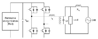
Fig. 4. Grid connected System [2]
IJSER © 2015 http://www.ijser.org
International Journal of Scientific & Engineering Research, Volume 6, Issue 1, January-2015 1244
ISSN 2229-5518
3 SYSTEM DESIGN
The requirement is to design a system which can integrate various forms of renewable energy sources with electrical grid in order to fulfill load demands. Because the system is focused on effective utilization of energy, the system designed should have very high efficiency. In other words great amount of study and research is done in order to prevent losses in the system.
Because the system is designed for domestic utilization,
therefore it must produce a pure sine wave output to supply
harmonic free power to the household load.The size of the
system is to be kept as small as possible so that it can be easily installed inside any house. The cost of the system should also be kept low so to make it as affordable as possible.
For the effective utilization of renewable energies, the sys- tem will deliver power primarily from the renewable energy
sources; if this power is insufficient then the deficient power will be taken from the electrical grid. This will utilize renewa- ble energy sources as much as possible.
Most renewable energy sources produce DC power which should be converted to AC to be delivered to the load. Moreo-
ver, the task of delivering power primarily from the renewable energy sources dictates that the real power delivered to the load from these sources should be controlled. The remaining power will be drawn from the grid by the load. Summarizing the above, an inverter is needed whose output power is to be controlled.
The system is implemented in such a way that the DC power from renewable energy sources is fed directly to the inverter. The inverter’s output is connected to the load while the grid is connected directly to the load. Output power of the inverter is controlled by varying its output phase angle δ with respect to the grid.
3.1 Grid Interfacing System
The system should be capable of converting DC input of 24V to AC output of 230V at 50Hz.The DC power is fed to a DC- DC boost converter with voltage gain. This simply boosts 24V DC to about 350V DC. The output of this converter is then fed to the inverter stage which converts it to 230V AC. The system implementation can be easily understood with Figure 5.
3.2 Battery Boost Converter
Battery boost circuit is design is based on a PWM controller IC
that is TL494. The IC applies a variable duty cycle pulses of
100 kHz to the step up transformer. On the secondary side of the transformer, the AC signal is rectified and filtered to make it a smooth DC. This DC is then fed to the H-bridge.
The transformer also has a low voltage winding for feed- back. The output of this winding is rectified and then fed to a
RC network. The internal error amplifier of the PWM control- ler IC senses the voltage of this RC network and changes the duty cycle accordingly.
Fig. 6. Boost Converter Output
3.3 Ferrite Core Transformer
Unlike the transformers using metallic stampings, where the core area can be adjusted by selecting the proper stack height, ferrite core of a particular size has an unalterable core area. Thus the design procedure for ferrite transformers is modified to suit this restriction [11]. The maximum power handling ca- pacity of a ferrite core transformer can be expressed in terms of the transmissible power P as:

Where
K = Operating waveform constant
f = Operating frequency
Bm = Maximum flux density swing of core material in
Wb/m2
J = Current density of wire in amp/cm2
Kw = Window area utilization factor
Aw = Window area of core in cm2
Ac = Core area in cm2
TABLE 2
TRANSFORMER VOLTAGE COMPARISON
Frequency (kHz) | Output (Volts) |
40 | 190 |
60 | 220 |
100 | 300 |
150 | 270 |
Fig. 5. Block Diagram of the Designed System
IJSER © 2015 http://www.ijser.org
International Journal of Scientific & Engineering Research, Volume 6, Issue 1, January-2015 1245
ISSN 2229-5518
3.4 The H-Bridge
The output of the battery boost converter that is 350V DC is fed to the H-bridge. The H-Bridge design uses 4 IGBTs 25n120. IGBTs are used because high voltages are supplied to the H- Bridge so a device with high reverse blocking voltages is re- quired. Another factor is that the device should be capable of withstanding any possible voltage spikes. 25n120 is capable of blocking 1200 V and has the current rating of 36 A. The pulses for driving the IGBTs are provided from the microcontroller
through an isolated gate-drive circuitry. The H-Bridge needs
to operate at a high frequency for effective harmonic elimina-
Where 𝜶1, 𝜶2, . . ., 𝜶N should satisfy 𝜶1<𝜶2<……..<𝜶N <𝝅/2.
The above equations for the calculation of angles cannot be
solved analytically therefore an alternative approach is re-
quired. An application by the name “Magic Sine Wave” is
used to calculate the firing angles.
Implementing SHE, first 26 harmonics were eliminated. Figure 9 shows the H-bridge output using SHE. Fig. 10 shows the frequency spectrum of the output. A second order low pass filter is added at the output to make the output waveform sinusoidal.
tion.
Fig. 7. Simple H-Bridge Topology [2]
3.5 Selective Harmonic Elimination (SHE)
The angles α1 to αn are calculated for different values of vo/vi. These values are programmed in the microcontroller in the form of lookup tables. The table contains all the delays required for all pulse generations. Depending upon the ratio of vo/vi the values of all the delays are selected from the table.
For elimination of harmonics, timing must be very precise
up to one instruction cycle. Every path of the code must take
exactly the same number of instruction cycles. This also re- stricts to use of interrupts. For the above stated reasons sepa- rate dedicated microcontroller is required for sine wave gen- eration.
To effectively eliminate harmonics and produce a pure sine
wave at the output of the inverter Selective Harmonic Elimina- tion (SHE) technique [12] is applied. In this method notches are created on the square wave at predetermined angles. The AC output voltage of a full-bridge inverter features odd-half and quarter-wave symmetry; therefore even harmonics are not present. To adjust the fundamental component and eliminate N-1 harmonics the output waveform should consist of N puls- es per half-cycle. A large number of harmonic components can be eliminated if the waveform can accommodate additional notch angles. As shown in Figure 8, if it is wished to remove third, fifth and seventh harmonics together with controlling the magnitude of the fundamental component (where N=4) we need to solve the following equations:
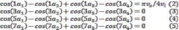
where α1 , α2 , α3 and α4 are the angles to be solved, vo is the output voltage of the full-bridge while vi is its input. The gen- eral expressions to eliminate N-1 harmonics are given by:
Fig. 8. Phase voltage wave for Selective Harmonic Elimination
[1]
Fig. 9. H-Bridge output using Simple Harmonic Elimination
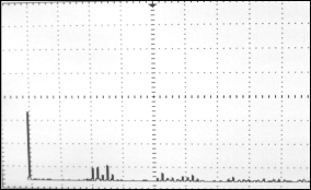
Fig. 10. First 26 Harmonics eliminated
IJSER © 2015 http://www.ijser.org
International Journal of Scientific & Engineering Research, Volume 6, Issue 1, January-2015 1246
ISSN 2229-5518
3.6 Load Sharing
The load sharing principle [3], [13] is used to control the pow- er output of the inverter. The power is varied depending upon the input and load so that the output is made stable. The pow- er output is controlled by changing the phase angle and mod- ulation index of the inverter.
If the power output of the inverter is less than the demand,
then the phase angle is adjusted to make the output of the in-
verter stable thus limiting the output power. The remaining demanded power is fed to the load by the grid. The power delivered by the inverter p is given by:
Where Vinv is the output voltage of the inverter, Vt is the grid voltage and δ is the angle between the grid voltage and inverter voltage. If the output power of the inverter is to be controlled the value of δ is to be varied keeping the inverter output voltage Vinv constant. By adjusting modulation index (M) and phase, the value of δ can be increased or decreased while keeping the value Vinv constant and thus varying the amount of power supplied by the inverter.
4 CONCLUSION
The objective was to utilize renewable energy sources as much as possible and at the same time minimizing electricity con- sumption from the utility company. The inverter was devel- oped using a ferrite core transformer which had the advantage of very low losses, small size and less weight. The designed was developed on the basis of load sharing principle. The an- gle δ, the angle between inverter output voltage and grid volt- age is varied to control the real power output of the inverter.
Selective harmonic elimination technique along with a LC
filter was used to remove the harmonics from the output volt- age. With the growing energy crisis, this will prove to be an effective solution especially for domestic users. The main no- ticeable effect will be the reduction in electricity bills. It will also ease the load on the utility company that provides elec- tricity.
ACKNOWLEDGMENT
Deepest gratitude is owed to Mr. Shehzad Hafeezi (Vice Pres- ident Mazik Global Inc.) for providing us with the ideas and resources also Dr. Haroon Rasheed (Head of Department, Bahria University, Karachi Campus) and Mr. Salman Zaffar (Assistant Professor, DHA Suffa University) for sound guid- ance without which we would never have had the chance to further our technical skills.
REFERENCES
[1] Bimal K. Bose, “Modern Power Electronics and AC Drives,” pp.
218−220, 2002.
[2] Muhammad H. Rashid, “Power Electronics Handbook,” 2nd ed, pp.
360−362.
[3] Muhammad Quamruzzaman and Kazi Mujibur Rahman, “Develop- ment of Control Strategy for Load Sharing in Grid-Connected PV Power System,” 5th International Conference on Electrical and Com- puter Engineering ICECE 2008, 20-22 December 2008, Dhaka, Bang- ladesh, IEEE 2008.
[4] PICREF-1 - Uninterruptible Power Supply - Application Note, http://www.microchip.com/stellent/idcplg?IdcService=SS_GET_P AGE&nodeId=1824&appnote=en010947.
[5] Labed Djamel and Boucetta Abdallah, “Power quality control strate- gy for gridconnected renewable energy sources using PV array, Wind turbine and battery,” 4th International Conference on Power Engineering, Energy and Electrical Drives, Istanbul, Turkey, 13-17
May 2013.
[6] Kurozumi, Kazuhiro et al, “Hybrid system composed of a wind power and a photovoltaic system at NTT Kume-jima radio relay sta- tion,” INTELEC, International Telecommunications Energy Confer- ence 1998, pp. 785-789.
[7] Riad Chedid and Saifur Rahman, “Unit Sizing and Con trol of Hy- brid Wind-Solar Power Systems,” IEEE Trans. Energy Conversion, Vol. 12, No. 1, pp. 79-85, March 1997.
[8] Francois Giraud and Zyiad M. Salameh, “Steady-State Performance of a Grid-Connected Rooftop Hybrid Wind-Photovoltaic Power Sys- tem with Battery Storage,” IEEE Transactions on Energy Conversion, Vol. 16, No.1, pp. 1-7, March 2001.
[9] Juan Manuel Carrasco, Leopoldo Garcia Franquelo, Jan T. Bi- alasiewicz, Eduardo Galván, Ramón C. Portillo Guisadoand, Ma. Ángeles Martín Prats, José Ignacio León and Narciso Moreno- Alfonso, “Power-Electronic Systems for the Grid Integration of Re- newable Energy Sources: A Survey,” IEEE Transactions on Industrial Electronics, Vol. 53, No. 4, August 2006.
[10] Ahmed Sharique Anees, “Grid Integration of Renewable Energy
Sources: Challenges, Issues and Possible Solutions.”
[11] M.C.Sharma, “Designing coils and transformers,” 1st edition, 2003, ISBN 81-7656-796-5.
[12] Raez – Ul - Haque, M. T. Iqbal and John E. Quaicoe, “Sizing, Dynam- ic Modelling and Power Electronics of a Hybrid Energy System,” IEEE CCECE/CCGEI, Ottawa, May 2006.
[13] Ajai Gupta, R P Saini and M P Sharma, “Modeling of Hybrid Energy
System for Off Grid Electrification of Clusters of Villages,” IEEE
2006.
IJSER © 2015 http://www.ijser.org