International Journal of Scientific & Engineering Research, Volume 4, Issue 4, April-2013 1280
ISSN 2229-5518
Reduction of Wingtip Vortices by Using Active
Means
Sangram Keshari Samal, Dr. P. K. Dash
Abstract— W ingtip vortices are strongly associated with induced drag for a three-dimensional wing. So it is important to study the characteristics of wing tip vortices in order to reduce the induced drag. In this paper, Numerical simulations of the tip vortices for an unswept and untwisted rectangular wing (NACA 0012) are carried out at a geometric angle of attack 10° using the commercial Computational Fluid Dynamics code(CFD). And Numerical results are compared with the low speed wind tunnel experimental measurements carried out by Chow at NASA. The numerical results that were obtained by using CFD code shows a good agreement with the experimental results. Few different configurations by using active means rather than wing tip shaping have been evaluated computationally to explore their potential to reduce the wing tip vortex qualitatively. It is shown by numerical calculation that the strength of the vorticity is significantly reduced when suction is applied on the wing tip and along a slot on the bottom surface near to trailing edge.
Index Terms— Active, Circulation, CFD, Drag, Induced, Vortex, W ingtip
——————————·——————————
1 INTRODUCTION
Aerodynamic efficiency is an important factor in the marketing of subsonic, commercial transport aircraft. Efficiency can be improved by increasing the maximum lift- to-drag ratio at the cruise flight condition. Because induced drag is typically 30 percent or more of the total drag on a subsonic transport in cruising flight [1]. A 10% drag reduction on a large military transport aircraft is estimated to save up to 13 million gallons of fuel over its lifetime [2]. The world total jet fleet is estimated to be around 17 thousand aircraft [3]. Such reduction in drag could result in fuel savings in fuel up to 1x10¹⁰ U.S. dollars ($). This drag is even more significant at low speed, during take offconditions, where it can account for 80-90% of the aircraft drag [4]. Reducing the strength of the wingtip vortices, diffusing them, and displacing them outboard will reduce the downwash on the wing at a given angle of attack, thereby resulting in an increase in aerodynamic efficiency (decrease in induced drag).
Besides the advantage of lowering operating costs, reducing wingtip shed vorticity, and therefore induced drag, may also reduce global warming because of the lower fuel consumption. The world’s commercial jet aircraft generate more than 600 million tons of carbon dioxide per year [5].
————————————————
• Sangram Keshari Samal
Research Scholar, Aeronautical Department,
Hindustan Institute of Technology and Science
Padur, Chennai - 603 103, INDIA
• Dr. P. K. Dash
Professor, Dept. of Aerospace Engineering, University of Petroleum and Energy Studies,
Dehradun-248007, INDIA
The intensity or strength of the wingtip vortices is directly proportional to the weight of the airplane and inversely proportional to the wingspan and speed of the airplane. The heavier and slower the airplane, the greater the angle of attack and the stronger the wingtip vortices. Thus, an airplane will create wingtip vortices with maximum strength occurring during the takeoff, climb, and landing phases of flight. The large jet aircraft can generate vortices which are larger than an entire small plane. These vortices can persist for several minutes, drifting with the prevailing wind. If a small plane is immediately preceded by a large aircraft on the runway, there is a high risk that the winds in a vortex will cause uncontrollable and sudden variations in altitude, possibly violently slamming the airplane into the ground without warning. Worse, the circular nature of vortices can flip a small plane upside down. At the low altitudes involved with landing and takeoff, this is completely unrecoverable.
Induced drag is often considered the price one must pay for flying, but in reality, the induced drag can be reduced. New devices, like winglets, vortex diffuser vanes, and wing tip sails have reached reductions in induced drag by up to 30% [2]. Munk[6], using inviscid induced flow analysis, showed how an elliptically loaded wing has the lowest induced drag for a planar configuration. However, in real air, vorticity can be dissipated by viscous effects to reduce induced drag (see non planar wings designed by Whitcomb[7].
In a finite wing, there is an opportunity for the pressures acting on the upper and lower surfaces to interact near the wing tip (Fig.1, [8]). The shorter the distance between the wing tip, the larger the downwash velocity and the induced drag [9]. The trailing vortex system also generates an upwash in the regions beyond the wing span and a
IJSER © 2013 http://www.ijser.org
International Journal of Scientific & Engineering Research, Volume 4, Issue 4, April-2013 1281
ISSN 2229-5518
downwash inside the wing span. This downwash produced by the trailing vortex system adds to the downwash produced by the bound vortex system(Fig.2, [10]).
The techniques for its tip vortices reduction include winglets, wingtip sails, Raked wing tips and Ogee tips. Much of the development work for the winglet was initiated by Whitcomb at NASA [7, 11].
Adding winglets to a wing can reduce and diffuse the vortex structure which originates at the tips [2, 12, 13]. But Winglets can not provide improved performance over all flight phases [14].Flight tests suggest that induced drag can be reduced up to 9% for a single sail and by up to 29% with three sails [15].Raked wing tips have been used on the Boeing 767 and Such wing tips reduce leakage from the high pressure region below to the low pressure region above the wing [16].Ogee tips show reduction in peak tangential velocity [17], reduction is 40 percentage.
Fig.1. Pressure equalization on the wing tip and vortices.
Fig. 12.Downwash due to bound and trailing vortices.
This paper concentrates on investigating different boundary layer suction configurations to reduce wingtip vorticity on subsonic flow. This effort concentrates on Boundary Layer Control (BLC) suction at or near the trailing edge of the wing tips. In this paper the CFD codes
have been validated with the experimental result done at NASA by Chow et al, and shows how BLC by suction can be used to reduce boundary layer vorticity shed at the trailing edge into the wake of the wing.
The methodology for this project is to first validate CFD code against NASA experiments data and then to investigate changes in vorticity using active means rather than wing tip shaping which is a passive means.
2 PROCEDURE
2.1 Overview
This paper presents a comparison between wingtip vortex flow field done by CFD simulations and experimental measurements done at NASA by Chow et al.[18], as a validation of the present numerical CFD simulations and several different configurations have been taken to explore their potential to reduce the wing tip vortex qualitatively.
The present simulations were run in ANSYS 13.0, which models fluid flow and heat transfer problems in complex geometries. This commercial CFD software solves the general transport equations using the finite volume method. Steady-state, transient, incompressible, compressible, inviscid, viscid, laminar, and turbulent flows can be solved with Fluent.
2.2 Complete Geometry Case
The computational domain includes a half-wing inside a wind tunnel (Fig. 3) such as the one used by Chow et al.[18]. The model is a rectangular wing with an aspect ratio of 1.5, 4 ft chord and 3 ft. half span. The airfoil section is a NACA 0012 at 10° angle of attack. The dimensions of the wind tunnel test section are 32x48 in. Free stream velocity is
170 ft/s yielding a chord Reynolds number of 4.6x10⁶.
Here the wing tip used was a rounded wing tip to get the vortex around the wing tip. Rounded wing tip provides better aerodynamic performance compared to squared wing tips. To get attached flow over the wing, strips were used as done by Chow et al.[18].Because at higher angle of attack, the flow is separated at the top of the wing. This separation causes additional drag and also tends to stall. To prevent these, strips was placed across the span of the wing at a distance of 0.1666 ft. ( 2 in.) from the leading edge and it has a width of 0.010416 ft. (0.125 in.).The strip extended around the tip and along the bottom surface of the wing (Fig. 4).
IJSER © 2013 http://www.ijser.org
International Journal of Scientific & Engineering Research, Volume 4, Issue 4, April-2013 1282
ISSN 2229-5518
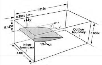
Fig. 3.Domain.
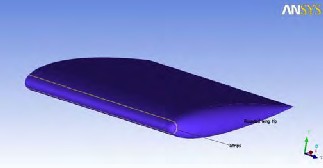
Fig. 4.W ing with strips.
2.3 Mesh generation
The geometry was imported to ANSYS ICEM CFD to generate meshes. ANSYS ICEM CFD provides advanced geometry acquisition, mesh generation, mesh optimization, and post-processing tools to meet the requirement for integrated mesh generation and post processing tools for today’s sophisticated analyses. Maintaining a close relationship with the geometry during mesh generation and post-processing, ANSYS ICEM CFD is used especially in engineering applications such as computational fluid dynamics and structural analysis.
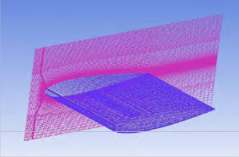
Fig. 5.W ing and wing-root wall surface with structured grids.
2.4 Solver configuration
After generating mesh it was feed to a solver to calculate the flow properties. Here the solver used was a FLUENT. ANSYS FLUENT is a state-of-the-art computer program for modeling fluid flow, heat transfer, and chemical reactions in complex geometries. ANSYS FLUENT uses a client/server architecture, which allows it to run as separate simultaneous processes on client desktop workstations and powerful computer servers. This architecture allows for efficient execution, interactive control, and complete flexibility between different types of machines or operating systems. ANSYS FLUENT provides complete mesh flexibility, including the ability to solve the flow problems using unstructured meshes that can be generated about complex geometries with relative ease. Supported mesh types include 2D triangular/quadrilateral,
3D tetrahedral/hexahedral/pyramid/wedge/polyhedral, and mixed (hybrid) meshes. ANSYS FLUENT also allows to refine or coarsen the mesh based on the flow solution.
2.5 Boundary Conditions
The inlet boundary condition was defined as a uniform inlet velocity =170 ft/s. The outlet boundary condition was based on a pressure outlet condition. The wind tunnel walls were defined as slip walls with a uniform velocity of Voo, except on the wall of symmetry, where the normal velocity component were set equal to zero. The wing surface was defined as a stationary surface.
2.6 Circulation across the Wingtip Vortex
The circulation, denoted by f is defined as [19].
f = - V. ds = - ('J × V). ds
Minus sign appears in above equation to account for
positive-counter clockwise sense of the integral and
positive-counter clockwise sense of the circulation
IJSER © 2013 http://www.ijser.org
International Journal of Scientific & Engineering Research, Volume 4, Issue 4, April-2013 1283
ISSN 2229-5518
For a plane it becomes[20]:
av au
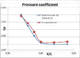
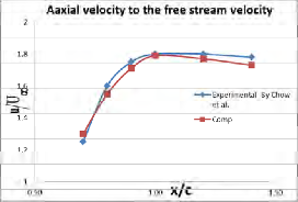
Fig.7 shows a comparison between pressure coefficient and axial velocity (u) to the free stream velocity (U oo ) measurements done by Chow et al. and simulations done in


f = (udx + vdy) = ax - ay dxdy
Where equation of vorticity (�) is
Fluent. The simulations show good agreement with the experimental data done by Chow et al.
av au


ax - ay = �
Where u is the velocity component in the x-direction and v
is the velocity component in the y-direction. The simulation
is obtained at an angle of attack of 10 for different x/c
locations and result is presented in Table -1 (Fig. 18).
3 RESULTS AND DISCUSSION
3.1 Validation of the CFD code
Pressure coefficient contours at vortex for different locations(x/c) are computed at 10° angle of attack and free stream velocity of 170 ft/s and compared with the experimental measurements done at NASA by Chow et al.[18]. Fig. 6 displays at various cross flow planes (x/c =
0.7, 0.8, 0.9, 1.0, 1.2 and 1.4) computed by Fluent code.
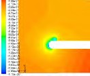
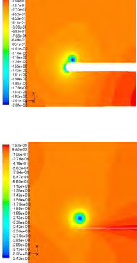
Cp contours at x/c=0.7 Cp contours at x/c=0.8
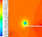
Cp contours at x/c=0.9 Cp contours at x/c=1.0
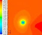
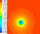
Cp contours at x/c=1.2 Cp contours at x/c=1.4
Fig. 6.Cp contours at different location (looking upstream from back)
Fig.7.Pressure coefficient and axial velocity in the wing tip vortex core in the downstream direction.
3.2 Wing Tip Vortex Reduction by different configurations
Few different configurations have been evaluated computationally to explore their potential to reduce the wing tip vortex. The goal of these simulations is to show that the wing tip vortex can be reduced qualitatively.
The wing model used in these simulations is similar to the one used by Chow. [18]. The model was a rectangular wing with AR=1.5, 4ft. chord, and 3 ft. half-span. The airfoil section was a NACA 0012 at 10° angle of attack. The free- stream velocity was 170 ft/s and the Reynolds number
4.6x10⁶. The computational domain was shown in Fig. 3.
3.2.1 Blowing air at the Wing Tip
Blowing is applied at the wing tip slot by introducing an outlet velocity of magnitude Voo=170 ft/s (Fig.8). Fig.9 shows two separate wing tip vortices is created instead of one wing tip. The inner blue color vortex is produced by the separation of the upper boundary layer, while the outer
IJSER © 2013 http://www.ijser.org
International Journal of Scientific & Engineering Research, Volume 4, Issue 4, April-2013 1284
ISSN 2229-5518
green color vortex (Fig.8) is a result of the separation of the bottom boundary layer.
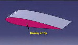
Fig.8. Blowing slots on wingtip
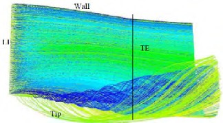
Fig.9.Streamlines on a wing with blowing at Voo through a slot at the wing tip.
Blowing at the wing tip with this slot geometry does not counteract the wing tip vortex; rather, it splits the vortex in two and increases their diameter.
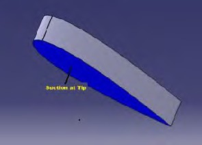
3.2.2 Applying Suction at the Wing Tip
Suction is applied at the wing tip slot by introducing an opening suction inlet velocity equal to Voo (Fig.10). The magnitude of the suction is not enough to cancel the inboard movement of the top streamlines, as can be seen in Fig.11.
Fig.10. Suction slots on wingtip
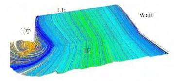
Fig.11.Streamlines on a wing with suction at the wing tip, as viewed from downstream.
Then, the wing tip slot suction velocity is increased to twice of Voo, and now the streamlines on top of the wing are almost straight (Fig.12). Unfortunately, the wingtip vortex is still present as shown by the outboard movement of the bottom streamlines(Fig.13).
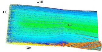
Fig.12.Streamlines on top of the wing when suction is applied at the wing tip.
IJSER © 2013 http://www.ijser.org
International Journal of Scientific & Engineering Research, Volume 4, Issue 4, April-2013 1285
ISSN 2229-5518
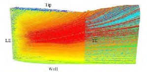
Fig.13.Streamlines on the bottom of the wing when suction is applied.
A suction velocity of twice Voo at the wing tip is enough to avoid the top streamlines from forming a shed wing tip vortex. But another method is required to counteract the bottom streamlines from producing a shed vortex.
3.2.3 Applying Suction on the Wing Tip and on a Slot on the Bottom wing surface
Suction equal to twice of Voo is applied on the wing tip to cancel the inboard movement of the upper surface streamlines, while the outboard movement is avoided by a suction slot along the bottom part of the wing (Fig.14). The suction slot on the bottom surface of the wing is 2 ft long. The magnitude of the suction velocity in this slot is equal to Voo. Fig.15 shows that the wing tip shed vortex was cancelled and the upper surface streamlines are straight. Also the bottom streamlines are straight (Fig. 16). Fig. 17 shows the streamlines when looking from the back.
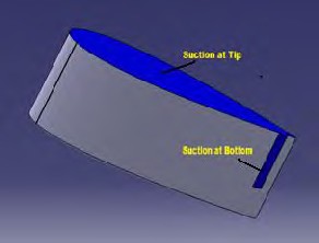
Fig.14. Suction slots on wing
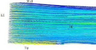
Fig.15. W ing tip vortex cancellation by wing tip suction and suction slot along the bottom
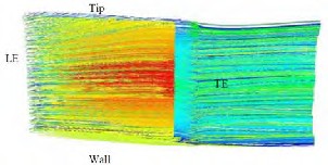
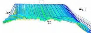
Fig.16. Bottom streamlines when suction is applied at the wing tip and along a slot on the bottom.
Fig.17.Streamlines when suction is applied at the wing tip and along the bottom of the wing.
The surface integral of the vorticity in the x-direction has been computed for two different configurations: the finite wing without suction and the finite wing with suction on the wing tip and on a slot on the bottom wing surface as presented (Fig.14). The integral has been calculated on seven surfaces parallel to the inlet across the computational domain. Fig. 18 shows that the vorticity is significantly reduced when suction is applied on the wing tip and along a slot on the bottom surface.
IJSER © 2013 http://www.ijser.org
International Journal of Scientific & Engineering Research, Volume 4, Issue 4, April-2013 1286
ISSN 2229-5518

TABLE 1.CIRCULATION ALONG THE X/C LOCATION (WITH AND WITHOUT SUCTION).
x/c | Tip Vortex Without Suction | Tip Vortex With Suction | Reduction (%) |
0.00 | 0.80 | 0.32 | 60% |
0.25 | 1.60 | 0.04 | 98% |
0.50 | 2.36 | 0.36 | 85% |
0.75 | 3.60 | 0.32 | 91% |
1.00 | 3.52 | 0.32 | 91% |
1.25 | 3.44 | 0.40 | 88% |
1.42 | 3.72 | 0.56 | 85% |
4
3
Without Suction
REFERENCES
[1] Zimmer, H.: Aerodynamic Optimization of Wings at Subsonic Speeds and the Influence of Wingtip Design. NASA TM-88534, 1983.
[2] Thomas, A. S., “Aircraft Drag Reduction Technology – A Summary,” Advisory Group for Aerospace Research and Development (AGARD), Report 723, Belgium, 1985.
[3] Airguide, “Jet Aircraft World Fleet Summary,” Air Guide
Online. 2006.
<http://www.airguideonline.com/aircr_wfleet.htm> (4
May 2006).
[4] Kroo, I. “Nonplanar Wing Concepts for Increased Aircraft
Efficiency,” VKI Lecture Series on Innovative Configurations and Advanced Concepts for Future Civil Aircraft, Stanford, 2005.
[5] Barnett, A., “Pace hots up in a World forever n the move,” Guardian Unlimited. 2006.
2
1
0
0 0.5 1 1.5
X/C
With Suction
http://observer.guardian.co.uk/carbontrust/story/0,16099,1
511925,00.html> (4 May 2006).
[6] Munk, M., “The Minimum Induced Drag of Aerofoils,” National Advisory Committee for Aeronautics, Report No. 121, pp. 373-390.
[7] Whitcomb, R., “A Design Approach and Selected Wind-
Tunnel Results at High Subsonic Speeds for Wing Tip mounted Winglets,” NASA TN-D-8260, 1976.
[8] Bertin, J. J. and Smith, M. L., Aerodynamics for Engineers
Fig. 18.W ing Tip vortex (with and without suction).
4 CONCLUSIONS
CFD simulations done in the current study to reproduce the experimental measurements done by Chow et al. [18] at NASA has shown very good agreement to predict the formation of wing tip vortices, and to obtain agreement for pressure coefficient and axial velocity values.
BLC to bottom suction slots is effective to straighten the streamlines. The suction slots at the trailing edge are more effective than the chord-wise slots for the cases tested. The optimum suction velocity on the bottom suction slot is Voo. The suction slots at the trailing edge with the combination of tip is more effective than the chord-wise slots for the cases tested. The best configuration is obtained when suction is applied at wing tip with the magnitude of twice the Voo and on the bottom surface of the trailing edge with the magnitude of the suction velocity is equal to Voo.
It is concluded based on the present study that tip-vortices, which are one of the most prominent aspects of lifting surface flows yet have been perceived difficult to tackle numerically, are tractable indeed with modern CFD code and can be predicted with a good accuracy. The wing tip vortex, which is cause of induce drag can be nullified using correct combination of suction and blowing at correct location.
3rd Edition, Prentice Hall, Upper Saddle River, NJ 1998. [9] Stinton, D., The Design of the Aeroplane 2nd Edition,
Blackwell publishing, London, Great Britain 2003. [10]Hoerner, S.F., Fluid Dynamic Drag Theoretical,
Experimental and Statistical Information, Published by the author, Brick Town, N.J. 1965.
[11] Whitcomb, R.T., “Methods for reducing subsonic drag
due to lift,” Special course on concepts for drag reduction, AGARD, France 1977, pp. 2-1 to 2-11.
[12] Webber, G.W. and Dansby, T., “Wing Tip Devices for Energy Conservation and Other Purposes,” Canadian Aeronautics and Space Journal, Vol. 29, No. 2, June 1983, pp. 105-200.
[13] Gerontakos, P., and Lee, T. “Effects of Winglet Dihedral on a Tip Vortex,” AIAA Journal of Aircraft, Vol. 43, No.
1, January,2006.
[14]Wu, J.M. et al., “Wing tip jets aerodynamics performance,” 13th Congress of the International Council of the Aeronautical Sciences/AIAA Aircraft Systems and Technology Conference, ICAS proceedings, Vol. 2, 1982, pp. 1115-1121.
[15]Spillman, J.J., “The Use of Wing Tip Sails to reduce
Vortex Drag,” Aeronautical Journal, September 1978, pp.
387-395.
[16] Aerospace Web, “Boeing 767 Raked Wing tips,” 2006.
<http://www.aerospaceweb.org/question/aerodynamics/q0
148.shtml> (1 Aug.2006).
[17] Dunham, R.E., “Unsuccessful Concepts for Aircraft Wake Vortex Minimization,” NASA SP-409, Wake Vortex Minimization Conference, Washington D.C., February 25-26 1976.
IJSER © 2013 http://www.ijser.org
International Journal of Scientific & Engineering Research, Volume 4, Issue 4, April-2013
ISSN 2229-5518
[18]Chow, J., Zilliac, G., and Bradshaw, P., "Turbulence Measurements in the Nearfield of a Wingtip Vortex," NASA Technical Memorandum 110418, February 1997.
[19]John D Anderson Jr, "Fundamental of Aerodynamics", Fifth Edition. McGraw Hill.
[20] E L Houghton and N B Carruthers, "Aerodynamics for
Engineering Students" Third Edition.
1287
IJSER IS)2013
http:1/www.ijserorg