International Journal of Scientific & Engineering Research, Volume 5, Issue 3, March-2014 990
ISSN 2229-5518
Rectangular Microstrip Patch Antenna for
Wireless Communications at 6.5 GHz
Ms. Neha Patel1, Prof.Jaikaran singh2 , Prof.Mukesh Tiwari3
Abstract—Due to the exis tenc e of growth in developm ent of low c ost, less weight, highly reliable, minimal profile antenn as f or wireless devic es, it pos es a new challeng e f or the des ign of antenna in wireless c ommunic ations . This paper pres ents des ign and simulation of a rec tangular microstrip patc h antenna at 6.5 GHz f or wireless c ommunic ations . This antenna h as 140 MHZ bandwidth, Return loss at c entre frequenc y has less than -16.70dB. T he beauty of this antenna i s the us e of single patc h which mak e it eas y to f abric ate c ons equently c ost of antenna bec om es c heap er. The rectangular mic ros trip patc h antenna is anal yzed us ing High Frequenc y Struc ture s imulator (HFSS) v 11.
Key words: Rec tangular Microstrip Patc h Antenna, Return Loss , VSW R, Bandwidth, High Frequ enc y Structure simulator (HFSS) v 11, W ireless c ommunic ation.
Microstrip patch antennas have drawn the attention of researchers over the past few decades. However, the antennas inherent narrow bandwidth and low gain is one of their major drawbacks [1, 2]. This is one of the problems that researchers around the world have been trying to overcome. Throughout the years, authors have dedicated their investigations to creating new designs or variations to the original antenna that, to some extent, produce wider bandwidths.
The patch antenna has been rapidly used in various
fields like space technology, aircrafts, missiles, mobile communication, GPS system, and broadcasting. Patch antennas are light in weight, small size, low cost, simplicity of manufacture and easy integration to circuits. More important is these can be made out into various shapes like rectangular, triangular, circular, square etc [1].
Many techniques have been suggested for achieving
the high bandwidth. These techniques includes: using
parasitic elements either in same or other layer [7], utilization
of thick substrates with low dielectric constant [4], and slotted
patch [5]. We have used a thick dielectric substrate having a low dielectric constant which provides better efficiency, larger bandwidth and better radiation. However, such a configuration leads to a larger antenna size. In order to design a compact Microstrip patch antenna, higher dielectric constants must be used which are less efficient and result in narrower bandwidth. Hence a compromise must be reached between antenna dimensions and antenna performance.
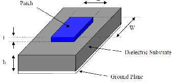
Microstrip patch antenna consists of a radiating patch on one side of a dielectric substrate which has a ground plane on the other side as shown in Figure 1.
————————————————
• Ms .Neha Patel: M.Tech Scholar (Digital Comm.), SSSIST, Sehore (M.P) India
• Prof.Jaikaran singh, Prof.Mukesh Tiwari: Assoc. Professor, ECE, SSSIST, Sehore (M.P)
The patch is generally made of conducting material such as copper or gold and can take any possible shape. The radiating patch and the feed lines are usually photo etched on the dielectric substrate [1, 3]. The patch is selected to be very thin such that t << λo (where t is the patch thickness). The height h of the dielectric substrate is usually 0.003 λo ≤ h ≤ 0.05λo. The dielectric constant of the substrate (εr) is typically in the range
2.2 ≤ εr≤ 12 r. Microstrip patch antennas are increasing in
popularity for use in wireless applications due to their low-
profile structure. Therefore they are extremely compatible for
embedded antennas in hand-held wireless devices such as cellular phones, pagers etc. The telemetry and communication antennas on missiles need to be thin and conformal and are often Microstrip patch antennas. Another area where they have been used successfully is in Satellite communication.
Microstrip patch antennas can be fed by a variety of methods [1, 2]. These methods can be classified into two categories- contacting and non-contacting. In the contacting method, the RF power is fed directly to the radiating patch using a connecting element such as a Microstrip line. In the non-contacting scheme, electromagnetic field coupling is done to transfer power between the microstrip line and the radiating patch. The four most popular feed techniques used are the Microstrip line (fig.2), coaxial probe (fig.3) (both contacting schemes), aperture coupling and proximity coupling (both non-contacting schemes).This paper uses microstrip line feeding technique.
IJSER © 2014 http://www.ijser.org
International Journal of Scientific & Engineering Research, Volume 5, Issue 3, March-2014 991
ISSN 2229-5518
The most popular models for the analysis of Microstrip patch antennas are the transmission line model, cavity model, and full wave model (which include primarily integral equations/Moment Method) [1,3]. The transmission line model is the simplest of all and it gives good physical insight, but it is less accurate. The cavity model is more accurate and gives good physical insight but is complex in nature. The full wave models are extremely accurate, versatile and can treat single elements, finite and infinite arrays, stacked elements, arbitrary shaped elements and coupling. These give less insight as compared to the two models mentioned above and are far more complex in nature. In this paper Transmission line model is used for designing the patch antenna.
This model represents the microstrip antenna by two slots of width W and height h separated by a transmission line of length L. The microstrip is essentially a non homogeneous line of two dielectrics, typically the substrate and air. The formulas used in this model for calculation of the dimensions are discussed in next section.
Design of microstrip patch antenna depends mainly upon three parameters, namely substrate and its dielectric constant, height of the substrate and resonant frequency. In this paper, selected three parameters are: Resonant Frequency (fr) = 6.5 GHz, Dielectric constant (εr) = 4.5, Height of the dielectric substrate (h) = 1.50 mm.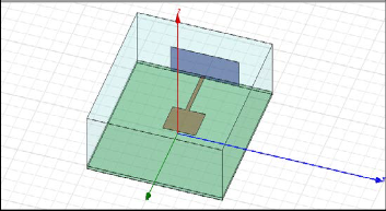
IJSER © 2014 http://www.ijser.org
INTERNATIONAL JOURNAL OF SCIENTIFIC & ENGINEERING RESEARCH, VOLUME 5, ISSUE 3, MARCH-2014 992
ISSN 2229-5518
The width of the Microstrip patch antenna is given by equation (1) [1, 2]:
It integrates simulation, visualization, solid modeling, and automation in an easy-to-learn environment where solutions to your 3D EM problems are quickly and accurately obtained. Ansoft HFSS employs the Finite Element Method (FEM), adaptive meshing, and brilliant graphics to give you unparalleled performance and insight to all of your 3D EM problems. Ansoft HFSS can be used to calculate parameters such as S-Parameters, Resonant Frequency, and Fields [6].
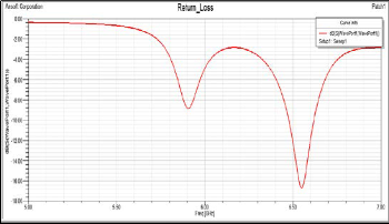
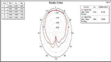
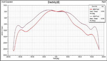
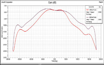
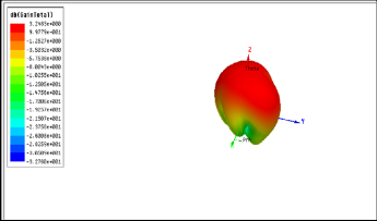
The Microstrip Rectangular patch antenna is simulated using Ansoft HFSS. The parameters evaluated were Return loss, VSWR, Radiation pattern, Directivity, Gain, 3D polar plot.
![]()
Leff = c / 2 f 0
ξ reff
L = Leff – 2 ΔL
Resonating frequency fr | 6.5GHZ |
Patch Width W | 24mm |
Patch Length L | 22mm |
Branch line length qw | 24.05mm |
Substrate height H | 1.50mm |
Relative permittivity Ԑr | 4.4 |
Feed line length | 15mm |
Feed line width | 2.75mm |
The software used to model and simulate the microstrip patch antenna is HFSS. HFSS is a high-performance full- wave electromagnetic (EM) field simulator for arbitrary 3D volumetric passive device modeling that takes advantage of the familiar Microsoft Windows graphical user interface.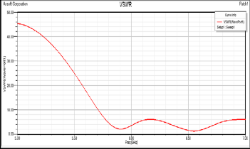
IJSER © 2014 http://www.ijser.org
INTERNATIONAL JOURNAL OF SCIENTIFIC & ENGINEERING RESEARCH, VOLUME 5, ISSUE 3, MARCH-2014 993
ISSN 2229-5518
Parameters Rectangular patch |
Resonant frequency 6.5GHz |
Bandwidth 140MHz |
Return loss(dB) -16.70 |
VSWR 1.34 |
Gain(dB) 2.65 |
Directivity(dB) 6.24 |
Thus the design and simulation of Microstrip rectangular patch antenna was successfully designed and analyzed using Ansoft HFSS. The performance parameters were achieved with Return loss -16.70dB, gain 2.65 dB and bandwidth 140 MHz for rectangular patch antenna. The use of slotted patch reduces the size of antenna and higher bandwidth, which is the area that can be improved with the proposed design.
[1] J Constantine A. Balanis; Antenna Theory, Analysis and
Design, John Wiley & Sons Inc. 2nd edition. 1997.
[2] Garg, R and Ittipiboon, A; “Micro strip Antenna Design
Handbook”, Artech House, 2001.
[3] D.M. Pozar, ―Microstrip Antennas, Proc.IEEE, vol.80, No.1, January 1992.
[4] Neeraj Rao, Gain and Bandwidth Enhancement of a Microstrip Antenna using Partial substrate removal in multiple layer dielectric substrate, PIER proceedings,
Suzhou, China, Sept.12-16, 2011.
[5] Isha Puri, Bandwidth and Gain increment of microstrip patch Antenna with Shifted elliptic‖al , SIlJoEtST ,
vol.3No.7, July, 2011.
[6] www.AnsoftHFSS.com
[7] Wood.C, Improved Bandwidth of Microstrip Antenna using parasitic elements, IEEE vol.127, Issue4, 11Nov, 2008, pp.-231-234
IJSER © 2014 http://www.ijser.org