Here in real time applications we have in built wheatstones bridge within a signal conditioner. Hence we describe the
same as a signal conditioner
International Journal of Scientific & Engineering Research, Volume 4, Issue 4, April-2013 417
ISSN 2229-5518
Lince Mathew
Abstract— The objectives of this paper is to deploy a wireless sensory network using strain gauges and analyze the perfor- mance of it, at different conditions and make the communication from those sensors in an optimized way so that sensing can be done in an economical way. As the name suggests, the deployment of a WSN including strain gauge sensors can be done, and the performance analysis is also done to know the behavior of the bridge at various site conditions. This paper is concentrating on different modules, and it deals with a complete sensing mechanism that can send the monitored data to all over the world, so that anyone can access and analyze at any time. The efforts of this study have been chiefly focused upon two aspects; how effi- ciently the bridge behavior can be studied if the sensors are placed wirelessly and how the sensor performance varies with dif- ferent conditions applied to it.
Index Terms: W ireless sensor networks, real time analysis, temperature effects, strain gauge, prediction mechanism, health monitoring, strain response
—————————— ——————————
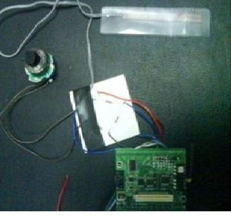
The objective of this paper was to deploy a wireless sensor network using sensors (strain gauges) for a highway infra- structure and analyze the performance of the bridge. The communication between the nodes and between base station is wireless. The first step was to connect the nodes and check for network activity. After successfully implementing that, the gauges are attached with DAQ boards and the sensor data has acquired in lab.The real time implementation was done on the bridge and the strain values were acquired over a period of time. The strain gauge response was studied and the bridge behavior is studied over a period of time with different condi- tions. The experimental set up for the real time deployment with warning system using WSN is shown in figure 1. The prototype consists of
1. Sensor
2. Wheatstones bridge
3. MDA 300 DAQ board
A sensor is a device to convert energy from one form to a
measurable electrical form and hence differ from a transducer
[1]. A strain gauge PL 60 is used for our application. 300MPa.
It can produce strain outputs in the compensation range 10 to
80oc. The gauge length is 60 mm and width is 1 mm. The pol- yester resin backing’s length is 74 mm and width is 8mm. the
lead wire resistance is 0.32Ω/m. Quarter bridge strain gauge is made for the project to avoid an unexpected resistance change due to temperature [4]. Maximum stress it can withstand is nearly 300MPa. The selected sensor is shown in figure 1.1
1.2 Wheatstone’s bridge
The use of Wheatstones Bridge is a conventional approach.
Here in real time applications we have in built wheatstones bridge within a signal conditioner. Hence we describe the
same as a signal conditioner
Fig 1 prototype of real-time warning system using WSN
1.2. 1 CIC SG 71 signal conditioner
The signal conditioning circuit used was CIC SG 71. The
output from the gauge is given to condioner which can be giv-
en to the MDA 300 as inputs. The inputs to MDA 300 should be in the range 0- 2.5 volts for further processing. So signal conditioning is achieved by this circuit. The CIC-SG71 and the new SG78 are DIN Rail Mountable Strain Gauge Signal Conditioners. It produces a non linearity and hysteresis effect within a small range of .05 % at full span. The CIC-SG71 can be used to condition the signal from any transducer with an output of 0.2 mV/V up to 15.0 mV/V.
IJSER © 2013 http://www.ijser.org
International Journal of Scientific & Engineering Research, Volume 4, Issue 4, April-2013 418
ISSN 2229-5518
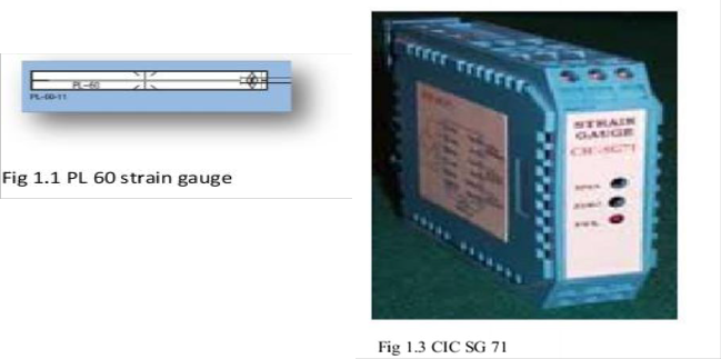
The CIC-SG71 provided a very precise excitation voltage to the transducer at 2.5, 5.0 or 10.0 VDC up to 100 mA. Outputs from the CIC-SG71 are selectable at 0 to 10, +/-
5, +/- 10, or 4-20 mA and are filtered at 1 kHz. High frequen-
cy response is optional up to 10 kHz. The CIC- SG71 also has an externally activated shunt calibration circuit as well as pro- visions for bridge completion resistors. It produces excellent linear output with high input impedance. It has a wide gain range 0.2 mV/v to 15.0 mV/V. The figure for signal condition- er is shown in figure 1.3
Analog sensors can be attached to different channels
based on the expected precision and dynamic range. Digital sensors can be attached to the provided digital or counter
channels. There are three excitation voltages—5.0 V, 3.3 V, and 2.5 V— available for exciting external sensors. They can be used for turning on active external sensors or they can be used in half bridge or full bridge sensors such as strain gauge, force or pressure measurement.
2. Working methodology
The PL 60 sensor is connected to the signal conditioning cir- cuit (CIC SG 71). The analogue signal can be amplified & given to the DAQ board (MDA 300) and can be send wireless- ly to the destination.The flow diagram is as shown in fig 1.2
. 3. Real time application
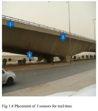
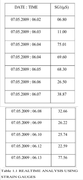
Here we have placed three sensors over the gulf bridge and a
real time analysis using strain gauges has been done. The
Graph thus obtained is plotted as time VS strain gauge. A warning can be given by real time monitoring of heavy vehi- cles over the infrastructure. Thus we can prevent any type of damages to the proposed system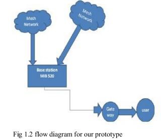
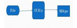
Fig 1.5 Flow diagram
IJSER © 2013 http://www.ijser.org
International Journal of Scientific & Engineering Research, Volume 4, Issue 4, April-2013 419
ISSN 2229-5518
.
4. Results & Conclusion
.
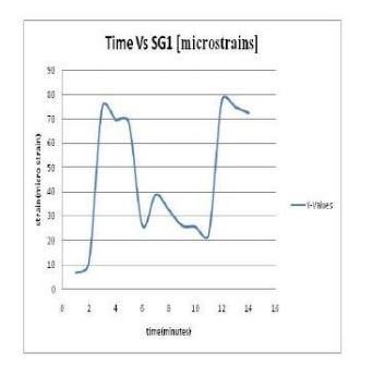
At present, comparative investigation of bridge be-
Fig 2 output analysis using a strain gauge on a bridge
havior with this level of detail and control of variables has been limited [2], [3]. This study presents a unique opportunity to develop a better understanding of local concrete bridge be- haviors and load paths through the substructure. Researchers and departments of transportation alike will benefit from this better and alternate method of understanding a bridge’s per- formance under vehicle loading and varying, long-term weather conditions. Application of this knowledge will lead to better planning for infrastructure health as well as improved
IJSER © 2013 http://www.ijser.org
International Journal of Scientific & Engineering Research, Volume 4, Issue 4, April-2013 420
ISSN 2229-5518
bridge design and hopefully this method will be used in near future with much awaited enhancements.
[1] A backup routing with wireless sensor network for bridge monitoring system by Ren-Guey Lee,Kuei-Chien Chen,
Chien-Chih Lai, Shao-Shan Chiang, Hsin- Sheng Liu, Ming- Shyan Wei
[2] . Fatigue analysis and life prediction of bridges with struc- tural health monitoring data by T.H.T. Chan, Z.X. Li *, J.M. Ko
[3] Statistical analysis of online strain response and its appli- cation in fatigue assessment of a long-span steel bridge by
Z.X. Li, T.H.T. Chan
[4] Developing strain gauges and instruments by TML
[5] Wireless Sensor Networks for Structural Health Monitor- ing: A Multi-Scale Approach by Tracy Kijewski-Correa, Mar-
tin Haenggi
IJSER © 2013 http://www.ijser.org