International Journal of Scientific & Engineering Research, Volume 6, Issue 3, March-2015
ISSN 2229-5518
125
Real Time Driver’s Drowsiness Detection System
Based on Eye Conditions
Asad Ullah, Sameed Ahmed, Lubna Siddiqui, Nabiha Faisal
Abstract— This paper presents a design of a unique solution for detecting driver drowsiness state in real time, based on eye conditions. Man y ap- proaches have been used to address this issue in the past. But this paper presents a simple algorithm based solution with min imum hardware require- ments. Under the controlled environment, the proposed system is successfully operated to generate results with approximately 90% accuracy. The sys- tem tends to use a web camera to capture a series of images. These captured images may fur ther be stored as individual frames in our system. The frames so formed, are provided as input to face detection software. In terms, our required feature (eye) is extracted from th e image. Individually working
on each eye, the system establishes a condition and suggests a specific number of frames with the same eye condition that may be registered. The result of these images may be taken as input to obtain the level of drowsiness that a driver may encounter at any certain sta ge while driving a vehicle.
Index Terms— Driver’s drowsiness, face detection, eye detection, eye condition, intensity values
—————————— ——————————
1 INTRODUCTION
Driver drowsiness is one of the biggest safety issues facing the road transport industry today and the most dangerous aspect of driver fatigue is falling asleep at the wheel [1]. Fatigue leads to sleep, it reduces reaction time (a critical element of safe driving). It also reduces vigilance, alertness and concentration so that the ability to perform attention-based activities (such as driving) is impaired. The speed at which information is pro- cessed is also reduced by sleepiness. The quality of decision- making may also be affected [2].
Driver falls in micro sleep, results in collision with object or
vehicle, or they can not recognize that he or she has drifted
into a wrong lane. The consequences of a drowsy driver are very dangerous and lead to loss of lives, casualties and vehicle damage.
The spectra of injuries are insidiously taking a greater toll on
human life and property worldwide. Overall 10-15 million
people are injured every year in road traffic collisions. It is projected that globally by 2020 RTCs (Road Traffic Crashes) will account for about 23 million deaths and RTIs (Road Traf- fic Injuries) will be the third leading cause of death and disa- bility as compared to their present ranking of ninth. In Paki- stan there are about 26 deaths from road traffic accidents per
100,000 populations, compared to Europe where the death rate
averages is 14.5 per 100,000 [2].
As the most important safety factor, it is necessary to make
some serious measures, in order to improve working condi-
tions of drivers, so that negative consequences subjected by a drowsy driver can be minimized.
Computer Science and Engineering contributes their responsi- ble role for development and betterment of society by provid- ing their valuable services in various fields belong to different aspects of life. Driver drowsiness detection system is such an example that can be used as a security measure that alerts the
drowsy driver while driving, in order to safeguard himself as well as others.
In this paper we proposed a real time driver drowsiness detection
system-RDDDS. It is non-intrusive system for monitoring driver drowsiness based on open and close conditions of eyes. Eye behaviors provide significant information about driver’s alert- ness and that if visual behavior can be measured then it will be feasible to predict driver’s state of drowsiness, vigilance or attentiveness [3]. The acronym RDDDS is used for a proposed system throughout the paper.
The paper describes the related work in section 2, proposed
architecture in Section 3, Implementation in Section 4. Experi- mental results in Section 5 and conclusion in Section 6.
2 RELATED WORK
The techniques of drowsiness/fatigue detection can be broadly classified into three major categories: Physiological measures, indirect vehicle behavior and directly observable visual behav- iors [4], [5].The best detection accurate techniques are based on physiological phenomena like brain waves, heart rate, pulse rate and respiration. These techniques are intrusive, since they need to attach some electrodes to the drivers, caus- ing annoyance to them. Some representative projects in this line are the MIT Smart Car [6], and the ASV (Advanced Safety Vehicle) project performed by Toyota, Nissan [7].
The electroencephalographic (EEG) algorithm, which is a
physiological sleepiness measure, has been studied to detect
drowsiness as well. Most of these studies have used EEG to validate the existence of drowsiness when other measures are being evaluated rather than as a fatigue detection measure [8], [9].
IJSER © 2015
http://www.ijser.org
International Journal of Scientific & Engineering Research, Volume 6, Issue 3, March-2015
ISSN 2229-5518
126
Ji and Yang propose a real-time prototype computer vision system for monitoring driver vigilance [10]. The main compo- nents of the system consist of a remotely located video CCD
camera, a specially designed hardware system for real-time image acquisition and for controlling the illuminator and the alarm system, and various computer vision algorithms for simultaneously, real-time and non-intrusively monitoring var- ious visual bio behaviors that typically characterize a driver’s level of vigilance. The visual behaviors include eyelid move- ment, face orientation, and gaze movement (pupil movement) [3].
Eriksson and Papanikolopoulos present a system to locate and
track eyes of the driver. They use symmetry-based approach
to locate the face in a gray image, and then eyes are found and tracked. Template matching is used to determine if the eyes are open or closed [11]. Singh and Papanikolopoulos propose a non-intrusive vision-based system for the detection of driver fatigue [12]. The system uses a color video camera that points directly towards the driver’s face and monitors the driver’s eyes in order to detect micro-sleeps.
Smith, Shah, and Lobo present a system for analyzing human driver alertness [13], [14]. The system relies on an estimation of global motion and color statistics to robustly track a per- son’s head and facial features.
PERCLOS (Percent Eye Closure) methodology, a video based
method that measures eye closure, is a reliable and valid de- termination of a driver’s alertness level. PERCLOS is the pro- portion of total time that the driver’s eyelids are closed 80% or more and reflects slow eyelid closures rather than blinks [15]. Liu, Xu and Fujimura present a real-time eye detection and tracking method that works under variable and realistic light- ing conditions [16].
Face LAB is a tool that can be used to measure driver visual
behavior, including fatigue and inattention [17]. It is different from most other measures f eyes closure and gaze direction [3].
The head position sensor system MINDS (Micro-Nod Detec- tion System) proposed by ASCI is conceptually designed to detect micro-sleep events occurring in association with head nodding through assessing the x, y, and z coordinates of the head through conductivity measurements [18].
3 PROPOSED SYSTEM- RDDDS
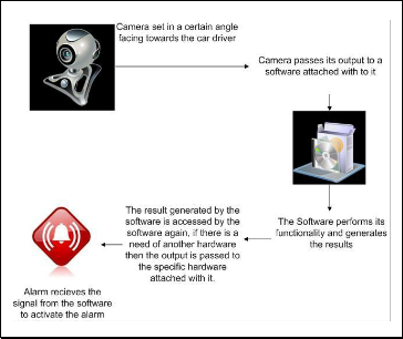
Fig 1. Presents the basic architecture for the proposed RDDDS. A web camera capable of capturing a video without blurring them with a resolution of six mega pixel minimum is used. Speakers are used for the proposed system as it generates the output in terms of an alarm.
Fig 1. Architecture of RDDDS.

Following subsections illustrates the series of steps organized for the proposed system – RDDDS
3.1 Camera settings and initialization
The camera must be placed at a distance of 40 cm to 50 cm from a driver. This distance is approximately equal to the dis- tance between the car steering and the driving seat. The cam- era must be placed at an angle of 45 degrees from the driver’s face. At an angle between 35-50 degrees the face can be cap- tured with perfection and ease.
The first step is initialization of a camera and video processing unit, it acquires an image of the driver's face. Therefore, it is
assumed that the eye is a plane Perpendicular to the optical axis of the camera, which is a photo eye 'in the central part of the frame.
3.2 Video Frames
When the system is initiated a delay of two to three seconds is experienced for capturing the image for the first time. This results in losing the data from the first three frames. The seg- ment of video thus obtained from the camera is then used to extract each segment of video frame i.e. 30 frames per second.
3.3 Face Detection
The RDDDS actually starts its execution once the face has been detected. The images obtained from the frames are now subjected to face detection part of the system. The most commonly used algorithm for face detection is the Viola Jones algorithm [19].
IJSER © 2015
http://www.ijser.org
International Journal of Scientific & Engineering Research, Volume 6, Issue 3, March-2015
ISSN 2229-5518
127
3.4 Eye Detection
Each face detected is stored for half a second to crop the image in order to detect the eye. Our proposed algorithm CropEye is used for eye detection. CropEye algorithm divides the face horizontally into two segments i.e. upper segment and a lower segment. Upper segment contains the image between the forehead to the eyes, and lower segment contains the image between the nose to the chin. We take into account the upper segment and lower segment is discarded. The upper segment again is divided horizontally into 2 segments, this time upper up segment from the forehead to an eyebrow and the upper lower segment from eyebrow to a lower eyelash. After the eyes have been extracted from the image it is then that the current frame is replaced by a new one. The eyes extracted are now categorized in two parts through vertical calibration - the left eye and the right eye.
I=Face segment/2
A=Upper segment B=Lower segment A/2
Now we get, A1=Upper_up segment A2=Upper_low segment A2/2
Now we get,
R=Right eye and L= Left eye
3.5 Check condition for open and closed eyes
After the eye has been detected, the next step is to detect the eyes condition either they are open or close, so for this pur- pose intensity values are used. A graph is plotted which calcu- lates the intensity distance in the eye separately through the eye lashes and eye brow and check the state of an eye on this intensity distance. If distance is large, eye is close and when distance is less, eye is open. The distance can be evaluated by analyzing the samples of images. Both the eyes are binarized to determine the threshold value and then the results are pro- duced. If the system encounters five consecutive frames with the eyes closed the alarm is triggered for the next five frames.
4 IMPLEMENTATION
The work under discussion is implemented in Matlab2012a. The RDDDS minimally uses six mega pixel webcam mounted on the dashboard of a car, without blurring them. The flow model depicted in Fig 2 shows the stepwise execution of RDDDS and will be discussed in the following subsections.
————————————————
Asad Ullah is a software engineer at Agilosoft,Karachi Pakistan
Sameed Ahmed is a Software Engineer at Access Group Pvt Ltd,Pakistan

Lubna Siddiqui is a lecturer at department of Computer Science of Bahria
University Karchi campus,Pakistan PH+92 21-111-111-028
E-mail: luna.siddiqui@bimcs.edu.pk

Nabiha Faisal is an Assistant Professor at Department of Computer and Sof t-
ware Engineerinf of Bahria University PH+92 21-99240002-6
E-mail: nabiha_faisal@bimcs.edu.pk
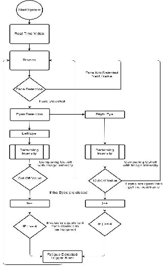
Fig 2. The Process flow of RDDDS. .
When the system is initiated a delay of two to three seconds is experienced for capturing the image for the first time. This results in losing the data from the first three frames. The sys- tem actually starts its execution once the face has been detect- ed. Each face detected is stored for half a second to crop the image in order to detect the eye. After the eyes have been ex- tracted from an image, the current frame is replaced by a new one. The eyes extracted are now categorized in two parts - the left eye and the right eye. Both the eyes are binarized to de- termine the threshold value and then the results are produced. If the system encounters five consecutive frames with the eyes closed the alarm is triggered for the next five frames.
Creating a real time system means high speed processing.
Thus it was decided after generating several results that our
proposed system will not be storing the old results as they had
no significance and consumed a lot of space therefore slowing
down the whole system. So we have taken each frame, gener-
ating and saving the results and replacing the previous frame
with the current new frame.
Once an image is obtained from a real time detection camera
its analysis takes a couple of seconds to generate the results
and the accumulation of many frames together will only result
IJSER © 2015
http://www.ijser.org
International Journal of Scientific & Engineering Research, Volume 6, Issue 3, March-2015
ISSN 2229-5518
128
in a degraded real time system, so it was concluded that for each second a frame rate should be decided. A frame rate on the average of four frames per second is taken in for pr o- cessing.
The algorithm implemented for object detection of this system
is Viola–Jones [19] algorithm. It is successfully implemented for the face(s) within a frame. This algorithm is also the most popular and most widely used algorithm for face detection. OpenCV library is used for the detection of a face.
This algorithm has the power of searching 60 frame and image
in just 0.09 seconds, so it can search approximately 5940 frames in an image in one second. Fig 3 shows how frames are formed.
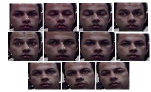

Fig 3. Series of images captured from a webcam and converted to frames.
Viola-Jones [19] algorithm is not only significantly used in face detection, but is as useful for facial feature extraction, in our case detecting the eye portion. Initially OpenCV was used to extract the eye portion in a face using the EYEPAIRBIG func- tion [20]. The portion of eyes were successfully detected but we also needed both the eyes identified separately. Even after repeated runs we were not able to get our desired results. Sometimes the eyes were not detected individually, at times any black spot in an image was identified as eyes. Thus it was concluded that even while being one of the most frequently used algorithm for face detection, these algorithms were not able to gather the results we wanted for our calculations. It was then that we designed a new algorithm for eye detection to serve our purpose significantly.
The Algorithm thus designed was named as cropper algo- rithm. The name thus given was on the basis of the fact that this algorithm performed our necessary cropping in an image. The algorithm proceeds in the following steps.
4.1 Selective Cropping of the face
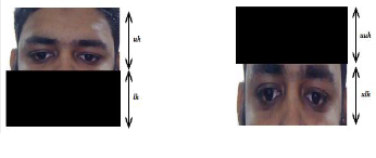
Initially the algorithm crops the face horizontally into two por- tions as shown in Fig 5(a). The upper half (uh) from head to nose and the lower half (lh) from nose to the chin. The same process is repeated on uh as shown in Fig 5(b), this time the two horizontal regions being upper-upper half (uuh) – from head to lower forehead and the upper-lower half (ulh) – from eyes to upper nose.
(a) (b)
Fig 5. (a) Detected face horizontally divided into 2 halves namely upper half uh and lower half lh , and (b) The upper half selected portion of the image is further horizontally divided into 2 halves namely upper upper half uuh and upper lower half ulh.
4.2 Disseminiating two eyes
The region selected from Fig 5(b) is ulh which contains the eyes, this portion is now divided vertically into two equal halves i.e the lefteye and the righteye regions. This gives us sufficient information for applying our proposed algorithm RDDDS. A function CropEye() is developed which is applied on Fig 6 to give us threshold values.
(a)
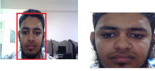
Fig 4. (a) Face detected in a frame (b) the facial area is separated us- ing Viola Jones algorithm.
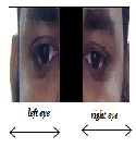
Fig 6. Eyes are extracted by vertical division of ulh and are termed as a left eye and a right eye.
4.3 Threshold Values

The test sample set thus obtained, comprised of 50 random subjects. The proposed algorithm was implemented to find the threshold value of each eye. These threshold values actually played a very important role in identifying the condition of the eye either as completely open or closed. In Table 1 we have included the largely varying values of the threshold of 10 ran- dom subjects. As we studied the patterns obtained from Table
IJSER © 2015
http://www.ijser.org
International Journal of Scientific & Engineering Research, Volume 6, Issue 3, March-2015
ISSN 2229-5518
129
1, it was observed that a threshold value of greater than 43
was identified as the absolute condition of drowsiness for a Pakistani face. This value may vary as facial features vary from region to region.
TABLE 1
Threshold Values of 10 Random Persons
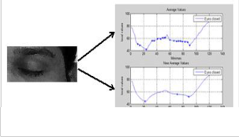
Fig 7(b). An average intensity variation on the face when eyes are closed.
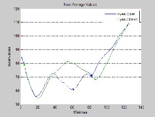
Once we have the average values individually for an open eye and a closed eye state, the final step executed is to find the comparative analysis between the two states. For this purpose we plotted two graphs, Fig 8 (a) with the average values for both the open eye and closed eye states, similarly Fig 8(b) de- picts the new average values for both open eye and closed eye.
4.4 Filtered Result
Once the threshold values have been specified, the next task is to filter the results. This is achieved first by converting the col- ored image into grayscale. A noise ‘salt & pepper’ of density
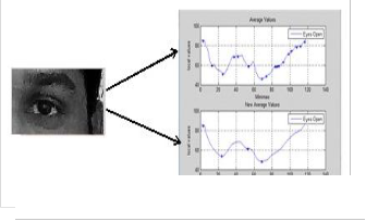
0.08 is added to filter the image appropriately. Finally, a medi- an filter of frame size 3x3 is applied to finally obtain a filtered image of the results and remove any insignificant data from the image. Fig 7 depicts two graphs for each state (open eye and closed eye). The first graph gives the average values for all the points identifying the eyes as open/close, whereas the se- cond graph, further averages the values to find the peaks of variations in the curves.
Fig 7(a). An average intensity variation on the face when eyes are open.
(a)


(b)
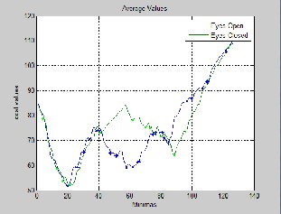
Fig 8. (a) The average values between minima and local values for both open and closed eye, (b) The new average values b e- tween minima and local values for both open and closed eye.
IJSER © 2015
http://www.ijser.org
International Journal of Scientific & Engineering Research, Volume 6, Issue 3, March-2015
ISSN 2229-5518
130
5 RESULT
The system is tested on a PC of Dual Core 1.0 GHz processor with 512 MB RAM. The system can process 15 frames for each second of size 280x140. The system is tested on 1500 sample frames and for 1442 correct result were achieved. The system has got only 58 error frames which were due to a wrong pic- ture capture under the extreme conditions which will be men- tioned in conclusion. The system is tested on 50 people and it generates more than 90% accurate results.
Step by step process is already mentioned in implementation
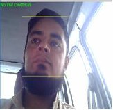
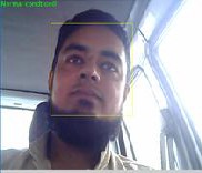
section. Fig 9 (a) – (f) depicts the test results of RDDDS with different eye conditions.


(a) (b)


(c) (d)


(e) (f)
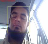
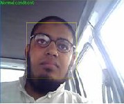
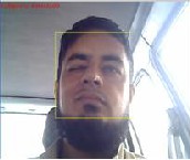
Fig 9. Test cases for different eye conditions (a) W ith ambient light and eyes open, (b) Face titled towards right and eyes open, (c) Eyes open wearing glasses, (d) Driver’s eyes closed, (e) Eyes closed in partial light and (f) One eye closed.
A data set of more than 25 eye conditions have been tested
with 90% accuracy. The system detects drowsiness at different levels. These levels may include complete eyes closed, partial closed eyes, one eye closed, right facing imaging, left facing images and many other states.
6 CONCLUSION
The proposed system can be used for driver’s safety and its consequences. The system detects drowsiness of driver through eye conditions. It based on face detection using well known Viola Jones algorithm, eyes are detected through pro- posed crop Eye algorithm which segments the face in different segments in order to get left and right eye. Conditions of open and close eye are determined by intensity values, distance between eye brow and eye lash is calculated. If calculated dis- tance is greater than threshold value, eyes are closed other- wise open. The threshold 43 and above is set for Pakistani eye feature, it can vary from region to region. An alarm is trig- gered if eyes are found to be closed for consecutive five frames. The system produces 90% accurate results for 50 dif- ferent faces. However, its limitation is detecting the eyes of person wearing glasses. Also it does not produce accurate re- sults if any reflective object is found behind the driver.
REFRENCES
[1] Ullah, I., & Szpytko, J. (2010). “Human fatigue model at road transport”. Journal of
KONES, 17, 467-474.
[2] NCSDR/NHTSA “Expert Panel on Driver Fatigue & Sleepiness; Drowsy Driving and Automobile Crashes”, Report HS 808 707, 1998
[3] Wang, Q., Yang, J., Ren, M., & Zheng, Y. (2006, June). “Driver fatigue detection: a survey. In Intelligent Control and Automation", 2006. WCICA 2006. The Sixth World Congress on (Vol. 2, pp. 8587-8591). IEEE
[4] Luis M. Bergasa, Jesus Nuevo, Miguel A.Soteli, Rafeal Barea, Maria Elena Lopez, “Real time system for monitoring driver Vigilance”, in IEEE Transactions on Intelligent Transportation Systems,Vol7, No.1, March’ 2006
[5] Qiang Ji, Xiaojie Yang, “Real-Time Eye, Gaze, and Face Pose Tracking for Monitoring
Driver vigilance”, Real Time Imaging, Vol8, no.5, pp 357-377, Oct’ 2002
[6] J. Healey, and R. Picard, “SmartCar: detecting driver stress”, in Proc. 15th Int. Conf.
Pattern Recognition, Barcelona, Spain, vol. 4, pp. 218- 221, 2000.
[7] A. Kircher, M.Uddman, and J.Sandin, “Vehicle Control and drowsiness,” Swedish
National Road and Transport Research Institute, 2002.
[8] M. Rimini-Doering, D. Manstetten, T. Altmueller, U. Lasdstaetter, and M. Mah- ler, “Monitoring driver drowsiness and stress in a driving simulator”, in Proc. Int. Driving Symp. Human Factors in Driver Assessment, Training and Vehicle Design, 2001.
[9] U. Svensson, “Blink behaviour based drowsiness detection”, Linkoping University, Swedish National Road and Transport Research Institute, 2004.
[10] Q. Ji, and X.J. Yang, “Real-time eye, gaze, and face pose tracking for monitoring driver vigilance”, Real-Time Imaging 8, pp. 357-377, 2002.
[11] Eriksson, M., & Papanikotopoulos, N. P. (1997, November). “Eye-tracking for detection of driver fatigue. In Intelligent Transportation System”, 1997. ITSC'97., IEEE Conference on (pp. 314-319). IEEE.
[12] Singh, S., & Papanikolopoulos, N. P. (1999). “Monitoring driver fatigue using facial
IJSER © 2015
http://www.ijser.org
International Journal of Scientific & Engineering Research, Volume 6, Issue 3, March-2015
ISSN 2229-5518
131
analysis techniques. In Intelligent Transportation Systems”, 1999. Proceedings.
1999 IEEE/IEEJ/JSAI International Conference on (pp. 314-318). IEEE.
[13] Smith, P., Shah, M., & da Vitoria Lobo, N. (2000, September). “Monitoring head/eye motion for driver alertness with one camera”. In Pattern Recognition, In- ternational Conference on (Vol. 4, pp. 4636-4636). IEEE Computer Society.
[14] P. Smith, M. Shah, and N. da Vitoria Lobo, “Determine driver visual attention with one camera”, Intelligent Transportation Systems, vol. 4, pp. 205-218, December
2003.
[15] D.F. Dinges, and R. Grace, “PERCLOS: A valid psychophysiological measure of alertness as assessed by psychomotor vigilance”, US Department of Transportation, Federal highway Administration. Publication Number FHWA-MCRT-98-
006.
[16] X. Liu, F.L. Xu, and K. Fujimura, “Real-time eye detection and tracking for driver observation under various light conditions”, in Proc. Intelligent Vehicle Symp., Versailles, France, pp. 344-351, 2002.
[17] G. Longhurst, “Understanding driver visual behaviour”, Seeing Machine Pty
Limited, 2002
[18] P.W. Kithil, R.D. Jones, and M. Jone, “Development of driver alertness detection
systems using overhead capacitive sensor array”, SAE Technical Paper Series,
982292, SAE International, 1998.
[19] Viola, P., & Jones, M. (2001). “Robust real-time object detection”. International
Journal of Computer Vision, 4, 34-47.
[20] Prajapati, J., Patel, A., & Raninga, P. “Facial Age Group Classification.Children”, 3,
16.
IJSER © 2015
http://www.ijser.org