
International Journal of Scientific & Engineering Research, Volume 4, Issue 1, January-2013
ISSN 2229-5518
RF MEMS Double Beam Lateral Switch
Characteristics Analysis Using Neural Network
S.Suganthi, K.Murugesan and S.Raghavan
Abstract— This paper presents Artificial Neural Network (ANN) implementation for Mechanical modeling of Radio Frequency Micro Electro Mechanical System (RF MEMS) lateral double beam switch. We propose an efficient approach based on ANN for analyzing the static and dynamic characteristics of RF MEMS lateral switch by calculating its characteristics parameters. ANN model were trained with five learning algorithms and the results from the neural model trained by Levenberg-Marquardt back propagation algorithm are highly agreed with theo- retical results. The neural network shows better results with highest correlation coefficient (0.5844) along with lowest root mean square er- ror (0.0539).
—————————— • ——————————
Micro Electro Mechanical System (MEMS) is the integration of mechanical elements, sensors, actuators and electronics on common silicon substrate by micromachining process [1]. The advancements in the field of designing sensors, micro ma- chines and control elements have facilitated much attention in the rapid developments of radio frequency (RF) MEMS. The first MEMS switch was demonstrated in 1971 using electrostat- ic actuation used to switch low frequency electrical signals [2]. When compared to the performance of MEMS switches, tradi- tional integration of PIN diode and GaAs FET in switching circuits is degraded because of high insertion and low isola- tion losses in high frequency (GHz) [3]. They are suffering from high power consumption and significant inter modula- tion product due to nonlinear characteristics [4].
On the other hand, the recently developed RF MEMS switches exhibit excellent switching characteristics over wide- band from RF to mm–wave frequencies (0.1 to 100GHz) with the following remarkable advantages such as extremely low insertion loss (0.1dB) and very high isolation upto 100GHz, near zero power consumption (10-200nJ/switching cycles), simple biasing circuit, potential for low cost and no inter modulation product (30-50dB better than PIN or FET switches) [4, 5].
Based on direction of motion, MEMS switches can be classi- fied as vertical and lateral switches. Most of the reported works are based on vertical switch which performs in wafer plane displacement and surface contact [6]. But the lateral switch performs in wafer plane displacement and side wall contact. The vertical switches have the drawbacks of stiction problem during the moveable structure release. But in the case
————————————————
• S.Suganthi is currently doing her research in the firled of RF MEMS in
Anna University, Chennai, India. E-mail:sugi19770@yahoo.com
• Dr.K.Murugesan is currently working as Professor in Sree Sastha Institute
of Engineering and Technology, Chennai, India.
• Dr.S.Raghavan is currently working as Professor in National Institute of
Technology, Trichy, India.
of lateral switches, the actuators, contacts, support structures and conducting paths can be fabricated in a single step and hence have the benefit of co-fabrication. Besides, it is easy to get mechanical force in opposing direction even when elec- trostatic designs are used [6, 7].
The superior qualities of RF MEMS switches make them as viable structure for various applications such as signal routing in transceivers applications [8], phase shifters in phase array antenna [3], impedance matching networks [6], wide band tuning networks, reconfigurable antennas, filters and related circuits [9]. MEMS concepts have been successfully applied in the development of RF switches to be used in the phase shif- ters which are having the benefits of low loss, low parasitic capacitance and high linearity [10]. In order to analyze and optimize the design of these complex structures, several tech- niques have been proposed in the past decade. Softwares based on Electromagnetic and Electromechanical [11] prin- ciples are also developed for commercial use. But these tech- niques are not much suitable for modeling of RF MEMS devic- es due to much computational time and efforts involved.
An accurate device characterization and efficient prediction of general input-output relationship can be achieved based on nonlinear mapping capabilities of Artificial Neural Network (ANN) [12]. ANNs have been utilized for modeling of inte- grated circuits in RF and millimeter wave frequency range [13]. In this work, threshold voltage and frequency response of a cantilever bean used in the double beam lateral switch which find application in high frequency transmitting and receiving signal routing has been analyzed using neural networks. Gen- eration of training and testing datasets are realized from MATLAB simulation. The cantilever beam used in the switch has been analyzed in terms of it static threshold voltage and dynamic frequency response and effective mass. Due to the optimization of generalized dimension of actuation part, the datasets for the mechanical design of the switch are obtained. The resultant input and output relationship are mapped using the neural model. Based on valid range of input parameters, neural networks are trained and tested. The neural models are trained with Levenberg-Marquart (LM), Bayesian Regulariza- tion (BR), Quasi – Newton (QN), Scaled Conjugate Gradient
IJSER © 2013 http://www.ijser.org
International Journal of Scientific & Engineering Research Volume 4, Issue 1, January-2013
ISSN 2229-5518
(SCG) and Conjugate Gradient of Fletcher – Powell (CGF) training algorithms. Although extensive time and effort are required for preparing the dataset, once the network is trained, the proposed model accurately predicts the device responses for arbitrary inputs within the desired range.
The low actuation voltage can be achieved through the opti- mization of the geometrical dimensions of the actuation part. The top view of the electrostatic actuator used in the modeling is shown in fig.2.
The actuator consists of four components: a suspended can- tilever beam serving as a movable electrode, an anchor on the substrate to support the cantilever beam, a fixed electrode op- posite to the cantilever beam and a contact tip. The cantilever beam OC is a beam-mass structure. For the beam part OA, the
width is
w1 and the length is
l1 . For the mass part AC, the
The detailed loss analysis of single beam lateral switch was
width is w2 and the length is (l 2 l3 ) in which l2 is the length
discussed with ON and OFF states in our previous work [13].
of the electrode section AB and l3
is the length of BC. The
In this paper, double beam RF lateral switch consisting of a Si- core finite ground coplanar waveguide (FGCPW) and an elec-
mass width w2
beam width w1
is designed to be relatively wider than the
so that low threshold voltage can be main-
trostatic actuator is designed as shown in fig.1 for ANN im- plementation since it provides low insertion loss and high power handling. FGCPW is formed by thick single-crystal- silicon plate that has been coated with thin layer of aluminum to make the RF signal propagation not only along the metal on the top surface, but also on the sidewalls of the transmission line. In this switch, two cantilever beams are employed and can be used as signal lines together to propagate RF signal [14]. Both the fixed connections of the two cantilever beams are from the same port and the two contact tips are on the oth- er port. At the free-end of the two cantilever beams, both ground lines extend towards the nearby cantilever beams to serve as their fixed electrodes respectively.
When sufficient DC bias voltage is applied between the can- tilever beam and the ground line, the cantilever beam is pulled toward the fixed electrode by electrostatic force until its free end hits the contact tip, resulting in the on-state of the switch. When DC bias voltage is removed, the mechanical stress of the beam overcomes the stiction forces and pulls the cantilever beam away, resulting in the off-state of the switch. Due to the asymmetrical layout of the two ports, the S-parameters ob-
tained and greater deformation of the electrode section may be
avoided.
2.2 Static Threshold Voltage
Assuming the electrode part of the cantilever beam is sub- jected to a uniform load, the equivalent stiffness k of the can- tilever beam can be derived by the expression [15]

Fig. 2. Top view of the electrostatic actuator
tained from the two ports are not reciprocal [3].

k 1 2 1 2
(1)
T 3 3 2
![]()
2 l 2 2l 2 l 3 E1 I1
(4l 3 9l l 2 6l l 2 6l 2 l
6l l l )E I
L 1 2 1
1 2 1 3
1 2 3 2 2 J
and E1 and E2 are the Young’s moduli of the narrow and wide part of the beam respectively. I1 and I 2 are the moments of inertia of the cross sectional area of the narrow and wide part of the beam respectively .We assume that
E1 E2 Esi 140GPa . (2)
I 1 w3 t
![]()
1 12 1
I 1 w3 t
(3)
Fig. 1. Schematics top view of Double beam RF lateral switch.
![]()
2 12 2
Where E si
is the Young’s modulus of the single-crystal-silicon
When a micro machined circuit is designed, it is important to consider the switching voltage required for its operation.
(140 GPa) and t is the height of the cantilever beam. After the deposition of aluminium on the top surface of the beam, it becomes the beam made of single crystal silicon partially cov-
IJSER © 2013 http://www.ijser.org
International Journal of Scientific & Engineering Research Volume 4, Issue 1, January-2013
ISSN 2229-5518
ered with aluminium. Therefore en by
E1 , E2 , I1 and
I 2 can be giv-
switching time calculation.
where m and b are the effective mass and damping coefficient of the simplified system . The quality factor Q of the cantilev-
E E si w1
2E Al w Al
er beam is determined by several variables such as the pres-
![]()
1 w 2w (4)
1 Al
1 3
sure, the temperature and the intrinsic material dissipation. The quality factor is also an important component for the switching time calculation.
![]()
I1 (w1
12
2w Al ) t
(5)
2.4 Dynamic effective mass
It is noted that the effective mass of the cantilever beam is not equal to the actual mass of the cantilever beam since only
E E si w1
2E Al w Al
the end portion of the cantilever beam is moving [14]. Assume
![]()
2 (6)
w2 2w Al
the cantilever beam is subjected to a concentrated load P at
the center of the electrode section of the cantilever beam.
1 3 Based on fig.2, we can consider the displacement yk
and ki-
![]()
I 2 (w2
12
2w Al ) t
(7)
netic energy Ek
spectively.
of the cantilever beam at three portions, re-
where
E Al
is the Young’s modulus of aluminium coated por-
The first part is the length of the beam ranging kinetic energy Ek1 is given by
0 5 x 5 l1 . Its
tion of beam (70GPa),
w Al
the thickness of aluminium depo-
1 P 2 4l 4
25l 3l
10l 2 l 2
sited at sidewalls of the silicon beam. Distance between the
ends of two electrodes g and the threshold voltage V can be
Ek1
![]()
2 m1
![]()
2E1 I1
1 1 2 1 2
30
(13)
related by solving the equation Fe (g )
2
Fr (g ) where
Fe (g )
0 I 2 tV
![]()
2g 2
(8)
Where m1
(p si w1
2p m wm )l1t
(14)
Fr (g )
k (g 0 g )
(9)
The second part is from the beginning of the electrode to the center of the electrode of the cantilever beam
![]()
are the electrostatic and restoring forces respectively with 0
is the permittivity of the air 8.854 X 10 12 F m .
(l1 x 5 ( l1
![]()
l2 2)) . The kinetic energy Ek 2 is given by
P 2 l 2 (l
l2 )
![]()
P 2 l l 2 (l
l2 )
The frequency response of the cantilever beam is useful to determine the switching time and the mechanical bandwidth of the lateral switch [14]. Using Laplace transform, the fre- quency response of the cantilever beam with small vibration
E k 2
1
![]()
2 m 2
L
E1 I1
![]()
8 E1 I1 E 2 I 2
P
![]()
E 2 I 2
24
2
2
![]()
5760 J
(15)
amplitude can be obtained as
Where m2
(p si w2
2p m wm )l2 t
(16)![]()
Y ( j ) 1 k
(10)
The third part is from the center of the electrode to the end of
![]()
F ( j )
1 ( 0 )
j (Q 0 )
the cantilever beam (l1
energy Ek 3 is given by
![]()
l 2 2 x 5 l1
l2 l3 ). The kinetic
where Y is the lateral displacement of the cantilever beam
1 P (l 2
l1l 2 )
Pl 2
2
1 l3
relative to the origin of the fixed electrode, F is the electros- tatic force, is the working angular frequency, k is the effec-
E k 3
![]()
m2
2 2E1 I1
![]()
8E 2 I 2
![]()
2 l 2
(17)
tive stiffness, 0
is the natural resonant angular frequency
and Q is the quality factor of the cantilever beam. 0 and Q
are expressed as
Therefore, the total kinetic energy
Ek is given by
![]()
0 k m
(11)
1 2
![]()
Q k ( 0 b)
(12)
E k E k1
Ek 2
E k 3
mym
2
(18)
where m and b are the effective mass and damping coefficient of the simplified system . The quality factor Q of the cantilev-
where the velocity
ym at the end of the cantilever beam is
er beam is determined by several variables such as the pres-
P(l 2
ym
l1l2 )
Pl 2
(19)
sure, the temperature and the intrinsic material dissipation.
The quality factor is also an important component for the
![]()
2E1 I1
![]()
8E2 I 2
IJSER © 2013 http://www.ijser.org
International Journal of Scientific & Engineering Research Volume 4, Issue 1, January-2013
ISSN 2229-5518
ANNs are biologically inspired computer programs to si- mulate the way in which the human brain process informa- tion. It is a very powerful approach for building complex and nonlinear relationship between a set of input and output data. The recent work by researchers demonstrated the ability of neural networks to learn and model a variety of microwave components, such as micro strip interconnects, spiral conduc- tors, CPW components and packing and interconnects [16]. Neural models can be much faster than original detailed EM/physics models, more accurate than polynomial and em- pirical models, allow more dimensions than table lookup models and are easier to develop when a new device
/technology is introduced [17]. The cost for developing neural models is mainly depending on data collection and training.
The power of computation is determined from connections in a network. Each neuron has weighted inputs, simulation function, transfer function and output. The weighted sum of inputs constitutes the activation function of the neurons. The activation signal is passed through a transfer function which introduces non-linearity and produces the output. During training process, the inter-unit connections are optimized until the error in prediction is minimized. Once the network is trained, new unseen input information is entered into the network to calculate the test output. Many types of neural networks developed for various applications are available in the literature.
The class of neural network and its architecture for a partic- ular model implementation depend on the nature of problem to be solved. The neural network architecture used in this pa- per is the MultiLayer Perceptron Neural Network (MLPNN). These networks having multilayer feed forward architecture composed of layers of computing nodes called neurons [16]. The MLPNN is one of the most extensively used ANN due to its well-known general approximation capabilities and limited complexity.
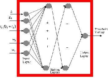
The MLPNN model used in this work consists of three lay-
ers: an input layer, an output layer and two intermediate or hidden layers. Each neuron in the input layer is acting only as a buffer for distributing the input signals xi to neurons in the
hidden layer. Each neuron j in the hidden layer sums up its
input signals xi after weighting them with the strengths of the
This is a least –square estimation method based on the max- imum neighborhood idea [20]. The LM method combines the best features of the Gauss-Newton technique and the steepest- descent method, but avoids many of their limitations. In par- ticular, it generally does not suffer from the problem of slow convergence.
This algorithm updates the weight and bias values accord- ing to their LM optimization and minimizes a linear combina- tion of squared errors and weights, and then determines the correct combination so as to produce a well generalized net- work. This algorithm can train any network as long as its weight, inputs and transfer functions have derivative func- tions [21].
This is based on Newton’s method but doesn’t require calcu- lation of second derivatives. An approximate Hessian matrix is updated. At each iteration of the algorithm, the update is computed as a function of the gradient. The line search func- tion is used to locate the minimum [22]. The first search direc- tion is the negative of the gradient of performance. In succeed- ing iterations the search direction is computed according to the gradient.
This method updates weights and bias values according to the conjugate gradient with Fletcher-Reeves. Each variable is adjusted to minimize the performance along the search direc- tion. The line search is used to locate the minimum point. Fletcher-Reeves version of conjugate gradient uses the norm square of previous gradient and the norm square of the cur- rent gradient to calculate the weights and biases [22].
This algorithm can train any network as long as its weights, net inputs and transfer functions have derivative function. This algorithm is based on conjugate directions but does not perform line search at each iteration. This was designed to avoid the time consuming line search.
respective connections
wij
from the input layer and compute
its output
y j as a function of the summation and hence
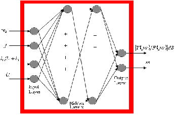
Two back propagation feed forward ANN architectures
y j f (I wij xi )
(20)
(ANN-S for static threshold voltage and ANN-D for dynamic
where f can be a simple threshold function, a sigmoidal [17]
or hyperbolic tangent function [18]. The output of neurons in the last (output) layer is computed similarly.
Training a network consists of adjusting weights of the net-
work using learning algorithms. During learning process, neural network adjusts the weights and thresholds so that the error between neural predicted output and sampled output is minimized. All learning algorithms used in this work are based on multilayer correction [19] learning algorithm called
frequency response and mass analysis) are proposed for anal-
ysis in this paper and are shown in fig 3(a) & (b). All model parameters are allowed to vary and MATLAB simulation is used to generate the datasets for ANN models. The circuit pa- rameters and dimension of actuated part are selected as input and threshold voltage is the output for ANN-S while length ratio, w2 , Q and frequency of operation are input and frequen-
cy response and effective mass are the outputs for ANN-D.
The selected ranges of input parameters used in the netwrok
back propagation. The five different training algorithms we![]()
for training are given as follows: 0.1 5 (l1 l1
l2 ) 5 0.95 ,
used in this work are described briefly as below.
4 m 5 g 0 5 10 m ,
2 m 5 w1 5 5 m
and
2.5 m 5 w2 5 20 m
for ANN-S and
01. 5 Q 5 3 ,
0.1KHz 5 f 5 100KHz
and
IJSER © 2013 http://www.ijser.org
International Journal of Scientific & Engineering Research Volume 4, Issue 1, January-2013
ISSN 2229-5518
440
m 5 (l1
l2 ) 5 540 m
for ANN-D respectively. The ratio
models, the mean square error (MSE) and the correlation coef-
of training to test data records employed in the experiment is
60:20. This means that with 468 data records, there are 280 records for the training set and 94 records for the test set. The
ficient (R 2 )as defined below are calculated in terms of the dif-
ference between the output of ANNs and training datasets:
chosen best trained Levenberg-Marquardt algorithm uses in-
put vectors and corresponding target vectors to train the neur-
MSE
![]()
I (xˆi xi )
(22)
al networks. The number of hidden units directly affects the performance of the network. Therefore, many experimental investigations are conducted. The number of hidden nodes determined to provide the optimal result are 10 for first and 6
N x 1
I (xˆ i
x )2
for second hidden layers respectively. R 2
i 1
N
(23)
I (x i
i 1
![]()
x i )
where N is the total number of data sets,
xˆi is input dataset, xi
![]()
is trained ANN output and xi is mean of xi .
where N is the total number of data sets, xˆi is input dataset,
![]()
xi is trained ANN output and xi is mean of xi .
(a)
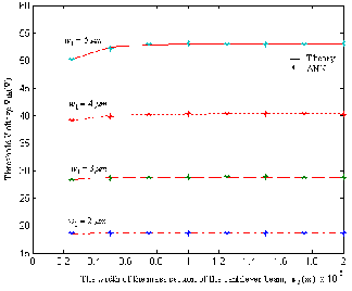
In order to obtain better performance, faster convergence and a simpler structure, the proposed ANN as shown in fig.3 was trained with five different training algorithms. To prove the efficiency and accuracy of the developed ANN models, the selected range of input values are used and the networks are validated. The comparison of threshold voltage Vth as a func-
tion of original gap between two electrodes, g 0 and the beam
width w1 are depicted in fig.4 (a) and (b) for ANN model and
simulation .
It is obvious from fig 4 (a) that the threshold voltage Vth
creases when the original gap between the two electrodes
de-
g 0
decreases or the length sum (l1 l2 )increases. When the canti-
![]()
lever beam length ratio l 2
(l1
l 2 ) is within the range of 30–
75 %, Vth only changes within 10% of the minimum value of
Vth which is referred to as
Vth
(min). The corresponding
![]()
length ratio [ l 2
(l1
l 2 ) min1 +l2)](min) to
Vth (min) is 50%
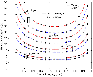
when w1
2.4
m, w2
5 m and w Al 0 .
(b)
Fig.3. Feed forward ANN architecture for (a) Static (b) Dynamic behavior of double beam switch
Thus the architecture of network obtained is 5-10-10-1 for
ANN-S and 4-6-6-2 for ANN-D. The number of input nodes is
5 and 4 for ANN-S and ANN-D respectively, representing the geometrical parameters of the switch that affect outputs. The numbers of output nodes are 1 and 2 for ANN-S and ANN-D respectively. In order to evaluate the performance of the ANN
(a)
IJSER © 2013 http://www.ijser.org
International Journal of Scientific & Engineering Research Volume 4, Issue 1, January-2013
ISSN 2229-5518
Two parameters namely correlation coefficient and Mean Square Error (MSE) values are used for the performance eval- uation of the models and comparison of the results for predic- tion of S-parameters. The higher value of correlation coeffi- cient and a smaller value MSE mean a better performance of the model. The results of the neural network based modeling of S-parameter calculation of different combination of input parameters with the used data set are provided in Tables 1 in terms of the correlation coefficient and mean square errors. From fig.4 &5 and the table 1, it is observed that there is an excellent agreement between the ANN & theory result.
TABLE.1
CALCULATED MEAN SQUARE ERROR (MSE) &CORRELATION COEF- FICIENT R 2 OF MASS & RESONANT FREQUENCY CALCULATION
(b)
Fig.4.Comparision of ANN and simulation results of calculated threshold
![]()
voltage Vth
(a) with various lengths (l1
l2 ), l2
(l1
l2 ) ratio, and initial
gap distance g 0 l3
10 m, wm
0 , w 2
5 m and w1
2.4
m (b)
with various cantilever beam widths (w1 , w2 )
(l1
275
m, l2
165
m) .
It also shows that l 2
![]()
(l1
l 2 ) (min) is almost independent of
the initial gap
g 0 and the length sum (l1 l2 ). Figure 4 (b)
shows that the threshold voltage Vth is more dependent on the beam width w1 than the mass width w2 . The effect of the mass
The above table shows that the neural network provides bet- ter results in terms of the higher correlation coefficient, which
width
w2 is negligible. The threshold voltage Vth
increases
measures the strength and direction of the linear relation be-
with beam width w1 .
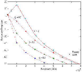
In the fig 5 (a), the variation in the frequency response of
the cantilever beam is simulated with different quality factors. It shows that the response amplitude at 15 kHz is increased when the quality factor ranges from 0.2 to 2.0. When Q 5 0.5 ,
it has a slow switching time; when Q � 2, it has a long settling
time. In practice, it is beneficial for the switching time that the quality factor of the cantilever beam is designed by 0.5 5 Q 5 2 .
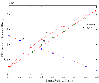
Figure 5(b) reveals the portion mass m1 , m2 and the effective mass m of a cantilever beam changes with the ratio of
tween two variables (actual and predicted values) of R2=0.2446 (0.5844) with minimum mean square error (MSE) of the model of 1.2087e-020 (0.0539) for threshold voltage calculation in terms of various length ratios and beam widths.![]()
l 2 (l1
l 2 )
when l3
10 m and l1 l2
440
m . It is found
that the effective mass m is mainly determined by the mass of
the electrode part m2 . The effective mass m is 5–85% of the
actual total mass of the cantilever beam
![]()
[m1
m2 (1
l3 l2 )]
![]()
when the ratio of l 2
(l1
l 2 ) is within the range of 30–75%.
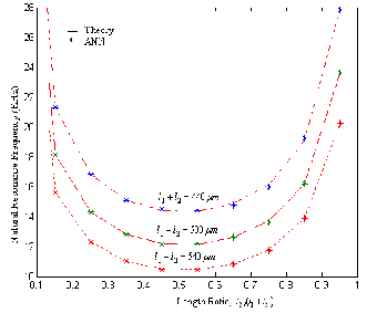
Figure 5(c) shows that the natural resonant frequency of the
cantilever beam changes with the ratio of l2 ![]()
(l1
l2 ) and the
sum of (l1 l2 ). It shows that the natural resonant frequency of
the cantilever beam does not changes significantly when
![]()
l 2 (l1
l 2 ) is within the range of 30–75%. For example, with
l3 10
m and l1 l2
440
m , the resonant frequency is 15 ±
![]()
0.5 kHz when l 2
(l1
l 2 ) is varying in the range of 0.3–0.75.
The natural resonant frequency of the cantilever beam de- creases with the increase of (l1 l2 ) due to the increase of the
effective mass and the decrease of the stiffness of the cantilev- er beam.
(a)
IJSER © 2013 http://www.ijser.org
International Journal of Scientific & Engineering Research Volume 4, Issue 1, January-2013
ISSN 2229-5518
cal results reveals that our proposed neural model is much useful for the behavior study of RF lateral double beam switches. Since the neural models presented in this work have good accuracy, require no tremendous computational efforts and less background information about bridges, they can be very useful for the development of fast CAD algorithms. A distinct advantage of neural computation is that, after proper training, a neural network completely bypasses the repeated iterative processes when new cases are presented to it. Since the training and testing time is less than few microseconds, the proposed neural model is quite fast in the design and loss analysis of lateral MEMS series switch.
(b)
(c)
Fig5. Comparison of ANN and simulated results of (a) Frequency re-
[1] Muldavin J B and Rebeiz G M, High isolation MEMS shunt switches part 1: Modeling, IEEE Trans Microwave Theory Tech (2000), 1045-
1052.
[2] C.Goldsmith, J.Ramtall, S.Eshelman, T.H.Lin and D.Demision, Cha- racteristics of micro machined switches at microwave frequencies, Proceedings of the IEEE MTT-S Dig (1996), 1141–1144.
[3] M. Tang, A.-Q. Liu, A. Agarwal and Z.-S. Liu, C. Lu, single-pole double-throw (SPDT) circuit using lateral metal-contact micro ma- chined switches, IEEE Trans Sensors and Actuators (2005), 187–196.
[4] Mohammad N. Mollah and Nema1 C. Karmakar, RF- MEMS Switch- es: Paradigms of Microwave Switching, Proc of APMC200 1, Taipei, Taiwan (2001), 1024-1027.
[5] Gabriel M. Rebeiz, RF MEMS Switches: Status of the Technology, Proc of the 12th Int Conf on Solid State Sensors, Actuators and Mi- crosystems, Boston (2003) 1726-1729.
[6] A Q Liu1, M Tang, A Agarwal and A Alphones, Low-loss lateral mi- cro machined switches for high frequency applications, J Microme- chanics and Micro engineering (2005), 157–167.
[7] Hah D, Yoon E and Hong S, A low-voltage actuated micro machined microwave switch using torsion springs and leverage, IEEE Trans. Microwave Theory Tech (2000), 2540–2545.
[8] G. M. Rebeiz, RF MEMS- Theory, Design and Technology (2003), John Wiley and Sons, Hoboken.
[9] Elliot R. Brown, RF-MEMS switches for reconfigurable integrated circuits, IEEE Trans. Microwave Theory Tech (1998), 1868-1880.
[10] B.Lakshanarayana and T.Weller, Distributed MEMS phase shifters on silicon using tapered impedance unit cells, IEEE MTT-S Digest
(2002) 1237-1240.
sponse of a cantilever beam with resonant frequency
f 15KHz and
k 0.94 (b) Effective mass and portion mass of the cantilever beam ver-
[11] Shyh-Chiang, Low actuation voltage RF MEMS switches with signal
sus the ratio of
![]()
l 2 (l1
l 2 )
for
w1 2.4
m , w2
5 m ,
frequencies from 0.25 GHz to 40 GHz, IEDM Technical Digest, Elec-
l1 l2
440
m , l3
10 m , w Al
0.6
m and
h 35
m . (c) Natu-
tron Devices Meeting (1999), 689-692.
![]()
ral resonant frequency versus the ratio of l 2
(l1
l 2 )
for
[12] Yongjae lce,Yonghwa Park,Feng Niu and Dejan Filipovic, Artificial
w2 5
m , h 35
m and w1
2.4
m , w Al
0.6 m .
neural network based macro modeling approach for two port RF MEMS resonating structures, IEEE Trans. Microwave Theory and
We have made a comprehensive analytical model based on MLP neural network for the design of static and dynamic lat- eral RF MEMS switch. The developed neural model matches closely with the literature results. The proposed ANN struc- ture can be effectively used for analyzing the characteristics of lateral RF MEMS switch based on static and dynamic beha- vior. The comparison between the neural model and theoreti-
Tech (2005), 261-266.
[13] S.Suganthi, K.Murugesan and S.Raghavan, Neural network based realization and circuit analysis of lateral RF MEMS series switch, Proc. of IEEE International Conference on Computer, Communica- tion and Electrical Technology (2011), 260-265.
[14] Ai Qun Liu, Aibin YuMing Tang, Muhammad Faeyz Karim and Selin Teo Hwee Gee, RF MEMS switches and integrated switching circuits- Design, fabrication and test (2010), Springer MEMS reference shelf.
IJSER © 2013 http://www.ijser.org
International Journal of Scientific & Engineering Research Volume 4, Issue 1, January-2013
ISSN 2229-5518
[15] Gere J M and Timoshenko S P, Mechanics of material (1997), 4th edition.
[16] Gregory L. Creech, Bradley J. Paul, Christopher D. Lesniak, Thomas J. Jenkins and Mark C. Calcatera, Artificial neural networks for fast and accurate EM-CAD of microwave Circuits, IEEE Trans. Micro- wave theory Tech (1997), 1794 -802.
[17] Younjae Lee and dejan S Filipovic, ANN based electromagnetic models for the design of RF MEMS switches, IEEE Microwave and Wireless components Letters (2005), 823-825.
[18] Zaabab, Q. Zhang, and M. Nakhla, Analysis and optimizations of microwave circuits and devices using neural networks models, IEEE MTT-S Dig, San Diego, CA (1994), 393 -396.
[19] S. Haykin, Neural Networks, A comprehensive foundation (1994), Macmillan College Publishing Comp.
[20] K. Levenberg, Method for the solution of certain nonlinear problems in least squares, Quart. Appl (2004), 164-168.
[21] D.J.C. MacKay, Bayesian interpolation - Neural Computation (1992),
415-447.
[22] C. Yildiz and M. Turkmen, A CAD approach based on artificial neural networks for shielded multilayered coplanar waveguides, AEU Int J of Elect. And Com (2004), 284-292.
IJSER © 2013 http://www.ijser.org