International Journal of Scientific & Engineering Research, Volume 2, Issue 12, December-2011 1
ISSN 2229-5518
Productivity Improvement on a CNC Lathe by Automatic Loading and Unloading of Throttle Valve Component
Rohan Kulkarni, S. Shivakumar and Roopa K rao
and unloading methods.
—————————— ——————————
Present techno economic scenario is marked by increasing competition in almost every sector of economy. The expecta- tions of the customers are on rise and the manufacturers have to design, and produce goods in as many varieties as possible to cater to demands of the customers. Thus there is a challenge before the industries to manufacture goods of right quality and quantity at right time and at minimum cost for their sur- vival and growth. This demands the increase in productive efficiency of the organization. Automation techniques play a pivotal role in increasing the productivity. Various automation techniques are used to analyze and improve the work me- thods, to eliminate waste and proper allocation and utilization of resources. Automation is concerned with the development, improvement, implementation and evaluation of integrated systems of people, knowledge, equipment, energy, material and process. Automation draws upon the principles and me- thods of engineering analysis and synthesis, as well as ma- thematical, physical sciences together with the principles and methods of engineering analysis and design to specify, predict and evaluate the results to be obtained from such systems. Engineers work to eliminate wastes of time, money, material, energy and other resources. Automation is an engineering approach to the detailed analysis of the use and cost of the resources of an organization. The objective of increasing prod- uctivity, reducing time, reducing cost and improvement in efficiency can be achieved using Automation Techniques. The
philosophy and motivation of the Automation profession is to find the most efficient and effective methods, procedures, and processes for an operating system, and to seek continuous im- provement. Thus, automation helps companies grow and ex- pand
SPM Tools, Ichalkaranji, has been serving a wide spectrum of Indian Industries for the past few decades. SPM Tools has developed wide range of CNC and Special purpose machines for different applications with a strong presence in the domes- tic market. SPM Tools has now moved on to compete in the market in line with its vision to move ahead with continual improvement in its product quality maintaining its highly competitive price.
A recent survey could reveal that there is a scope for prod- uctivity improvement by using these machines by using some automation techniques at much lower rates.
The various operations, loading, and unloading methods were studied and the following problems were identified
Sequence of performing the operations was not proper.
Production rate was meeting by taking extra ma- chines.
Labor fatigue was more.
IJSER © 2011
International Journal of Scientific & Engineering Research, Volume 2, Issue 12, December-2011 2
ISSN 2229-5518
Cycle time was higher because of manual load- ing and unloading of the components.
Cutting time was higher because of turret index-
ing.
SPM Tools produce several assemblies of various machines which include CNC, VMC, and Broaching Ma- chines etc. This paper concerns product KWAG throttle valve- which is produced on Safal Turn 4 CNC machine. There are eight types of throttle valve components with different de- mand from the customer.
Throttle valve is the fast moving component in Cli-
max Enterprises. Various sized throttle valves are routed
through several machines. . Throttle valve component has four operations on one side namely facing, chamfering, drill- ing, and grooving. These all operations are carried out on CNC Turning centre (Safal 4 make). The monthly requirement of this component is 3, 00,000 pieces.
The machine has an eight station turret on which three tools are posted. The various tools used are: Carbide form tool for grooving, Carbide form Tool of 6mm for facing and Com- bination drill 0f size 3.06mm/3.20mm.
The loading and unloading of these components is
done manually.
To meet the required demand, company is using Saf- al 4 and Safal 5 CNC machines. These machines operate for two shifts per day of 8 hours each. Company operates 26 days per month.
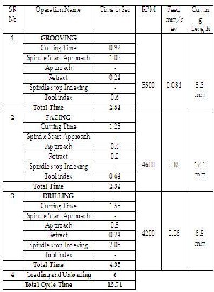
Time required to complete one component on CNC machine is calculated and it is tabulated in table
3.1.Taking that as ideal cycle time, ideal production
rates are calculated. By considering operators overall effi- ciency the actual production rate is also calculated
TABLE1
CYCLE TIME CALCULATION
From above table the ideal production rate is calculated as follows
Per hour Production rate on each machine is 3600/24.1 = 150 components/hour.
Per shift production rate on each machine is 150 x 8 = 1200
components/shift.
For two shifts, the production rate on each machine is 1280 x 2
= 2400 components/day.
Monthly production rate of each machine is 2400 X 26 = 62,400 components per month.
Required demand is 3, 00,000 components per month. There- fore total no. of machines required are 3, 00,000/62,400= 4.8 i.e.
5 machines.
Therefore 5 machines can produce 2400 X 5 X 26 = 3, 12,000 components per month
Total no of operators required per day is 10 (for two shifts, on
5 machines)
The production rate is highest during the early hours of each shift. This is because the operator is fresh and has highest efficiency.
Considering operator’s overall efficiency to be 85%, the per hour actual production rate becomes
150 x 0.85 = 128 components.
Per shift production rate is 128 x 8 = 1024 components
IJSER © 2011
International Journal of Scientific & Engineering Research, Volume 2, Issue 12, December-2011 3
ISSN 2229-5518
Per day production rate is 1024 x 2 = 2048 components.
On 5 machines, the production rate is 2048 x 5 = 10,240 com- ponents.
Monthly production rate is 10,240 x 26 = 2, 62,240 components
The company is falling short by 33,760 components to meet the required demand.
To fulfill this demand company has installed sixth machine. Because of which production rate achieved is 3, 19,488 com- ponents per month. The installation of sixth machine has add- ed two more operators. So the total no. of operators required is
12 to fulfill the demand.
The existing study shows the different operations that are to be carried out on throttle valve component and asso- ciated time calculations. It is observed that tool indexing time is bit high. It is analyzed as follows.
i) Tool has to travel from its home position to
cutting position
ii) Tool has to approach the job
iii) Tool has to perform the cutting
iv) Tool has to retract
v) Tool change for next operation
A significant amount of time is wasted in tool indexing.
Since loading and unloading operations are done ma- nually on the machine the time required to perform those op- erations may also vary. This is because the operator cannot perform the task with same frequency all the time. So there is a scope for development of such a method which can reduce the efforts of operator by keeping the loading and unloading time constant all the time.
From the study of existing scenario it is seen that the
company is not meeting its monthly demand. The company is making use of extra machines and operators. To fulfill the de- mand company is taking extra time which is not feasible. It is adding extra cost to the company. The detailed study of cycle time and loading and unloading methods it seen that there is a scope for improvement of productivity. The total cycle time can be brought down.
Table 1 shows total cycle time in detail. Based on this
table current production rate is calculated and it is found that company is not meeting the required demand. Still there is a scope for bringing this cycle time down.
Pneumatic type of automation is selected for the de- velopment of automatic loading and unloading method. The main reason behind selecting pneumatic system over hydrau- lics is liquids exhibit greater inertia than do gases. Therefore, in hydraulic systems the weight of oil is a potential problem when accelerating and decelerating actuators and when sud-
denly opening and closing valves. Liquids also exhibit greater viscosity than do gases. This results in larger frictional pres- sure. Since the weight of the component is only 30 grams the pressure required to handle the component is less. For this application, pneumatics is much more suited since it is fast in actuating and deactivating and economical compared to hy- draulic systems.
From Festo Catalogue
a) Conditions at conveyor usage
b) Movement of Components : By Gravity c) No. of parts on the tray, n: 22
d) Weight of each part, m : 30 grams e) Angle, a : 13
f) Distance between the fingers, h : 18.24 mm (Diameter
of the job)
The selection of angle is a critical parameter. The ideal condition would be zero degrees. With zero degree, some ex- ternal force is required to push the components into the chute. Therefore the tray has to be inclined at some angle so that gra- vitational force should help in moving the jobs into the chute. If the inclination is more, load coming on the separator will also be more. On the other hand, if the inclination is too less then also parts cannot slide. This is because the job is having some burrs. Due to this parts cannot slide that easily. The in- clination is obtained by trail and error method. At a certain angle these parts move very easily without any obstacles. The angle obtained by trial and error method is 130.
g) Geometry of the feed separator:
h) Horizontal distance between part and reference line, L
: 57.5 mm
i) Vertical distance between part and reference line, R : 0 mm
j) Pressure, p : 4 bars
Based on these inputs software provides us different
type of separators available and which one is suitable
for the mentioned working condition. The Separator selected is HPV-14-20-A b) Gripper
Selection of the gripper with respect to weight of the compo- nent:
Although conditions differ according to the work piece shape and the coefficient of friction between the attachments and the work piece, select a model that can provide a gripping force of
10 to 20 times the work piece weight, or more. If high accelera-
tion, deceleration or impact forces are encountered during motion, a further margin of safety should be considered.
IJSER © 2011
International Journal of Scientific & Engineering Research, Volume 2, Issue 12, December-2011 4
ISSN 2229-5518
Now let us assume the gripping force to be at least 20 times the work piece weight.
The weight of the work piece is = 30gm = 0.030kg
Required gripping force,
F = 0.030 kg x 20 x 9.8 m/s² = 5.88 N
Thus minimum gripping force on the work piece = 5.88 N
a) Information about object and gripper finger b) Application : Gripping without eccentricity c) Information about the object:
d) Distance 0-line -> centre of gravity: 47 mm e) Weight of the object: 30 grams
f) Required stroke: 5 mm
g) Data for a single gripper finger:
h) Weight of one finger gripper: 2.5 x 1.3 x 1.3 x 2.7 = 11
grams 1000
i) Distance 0-line -> centre of gravity: 13 mm
j) Distance 0-line -> gripping point: 47 mm
k) Acceleration in: Z direction
l) Maximum linear acceleration: 1 m/s2
m) Mounting position
n) Gripper position: Horizontal
o) Gripping direction: Closing
p) Gripping with: Positive engagement
q) Gripping inclination: 300
r) Working pressure: 4 bars
s) Co efficient of friction: 0.25
t) Safety factor: 1.5
u) Device temperature: 300 C
The Gripper selected is HGR-1-A radial gripper.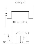
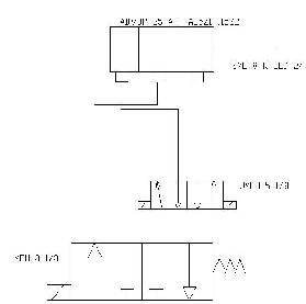
b) For Gripper
Fig 1 Cylinder Working
The selection of pneumatic cylinder is done based the follow- ing analysis.
We know that,
Force = Pressure x Area
Area = (Force/ Pressure) x Factor of safety
(π/4) x d2 = (0.030/4) x 2
d2 = (2 x 4x 0.030)/ (4 x π)
d = 0.138 cm
d = 1.38 mm
Required Piston Rod Diameter = 1.38mm
Therefore, we have to select cylinder with
minimum available diameter i.e 25 mm.The selected cylinder is ADVUP-25-A-P-A85Z1-115Z2.
c) For Separator
Fig 2 Gripper Workng
a) For Cylinder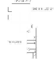
Fig 3 Separator Working
It is seen from the table 4.5.1 a significant amount of time is consumed in tool indexing when a turret is used. The turret used in Safal 4 Turning centre can accommodate 8 tools. The process of metal cutting is as follows. Tool from its home position comes near the work piece i.e. tool index. Then the tool approaches the work piece. Then it performs the cutting
IJSER © 2011
International Journal of Scientific & Engineering Research, Volume 2, Issue 12, December-2011 5
ISSN 2229-5518
operation. Once cutting has been taken place the tool retracts back. Then spindle stops. The next tool for next operation is indexed. To perform operations there has to be three times indexing.
Fig 4 Linear Tooling Arrangements
On throttle valve component the number of opera- tions those have to be performed are fixed. Therefore the tool movement can be done linear instead of circular indexing type. In linear tooling arrangement tools are placed on a block in a straight line as shown in figure 4.9.1. This makes the tool advancement and retraction quick. A significant amount of time can be saved which is lost in tool indexing.
The advantages of linear tooling arrangement are as
follows:
i) Cycle time drastically comes down. Since the cycle time goes
down, productivity obviously improves. From cycle time cal-
culations it is seen that by using turret type of tool indexing total cutting time was 9.6 seconds (2.7 sec for grooving, 3.6 sec for facing, 3.3 sec for drilling). Total cycle time including tool change time, tool approach time, tool retract time was 24.1 seconds. By making use of the linear tooling arrangement the tool approach time, tool indexing time can be brought down.
ii) Increased efficiency.
iii) Weight on the machine reduced. The total weight of the
turret used in Safal 4 turning centre was 40 kilo grams. This heavy weight leads to some inertia problems. The weight of linear tooling system along with the sleeves is only 4 kilo grams.
iv) Improvement in the quality of the product.v
v) Easy maintenance. Turret type of tool indexing has its own maintenance problems. The turret used in Safal 4 was PRA- GATI BTP-6. It has 18 oil seals which have to be replaced when they get damaged. Also turret oil has to be replaced af- ter every six months. The turret torque motor has to be re- placed after every three months. If any short circuit takes place it has to be rewind.
vi) Skilled operator not required. If any breakdown takes place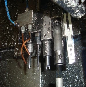
to identify that a skilled person is needed when turret is used. Unless and until the problem is attended machine is kept off. That is not a case with linear tooling arrangement.
The complete assembly is as shown in the figure 4. The
working of the system is as follows. The components are
loaded in the chute. The chute is inclined at an angle. The
parts move by gravity force. The chute guides the components into loading tube. The loading tube houses these components. One end of the cylinder is connected to the loading tube. The cylinder used here is multi-stroke cylinder. Total stroke length is 115mm. It is devided into two strokes. In the first stroke piston moves to 85 mm and in the second stroke it moves 30 mm. In first stroke it pushes the component to 85 mm. It means the componet just comes out of the loading tube. In second stroke the component moves further 30mm. During this stroke the component is admitted into the chuck. Separator blades holds the components and discharges one by one into the loading tube. Once the part gets machined the pneumatic gripper holds the machined component and unloades it from chuck and finally drops it down.
A new program has been developed for linear toolin
with little modifications to old program.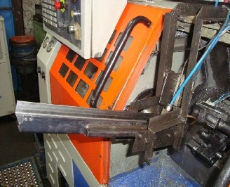
IJSER © 2011
International Journal of Scientific & Engineering Research, Volume 2, Issue 12, December-2011 6
ISSN 2229-5518
Earlier 12 operators were required to fulfill the demand. Operator wages are as follows: Rupees 4500 per month per operator.
For 12 operators, 12 X 4500 = 54,000 Rupees per month
For one year, 12 X 54,000 = 6, 48,000 Rupees
Since loading and unloading is done automatically, operator
only has to feed the parts on chute. Therefore two machines
can be easily handled by one single operator. Hence total number of operators required is 4.
But now company requires only 4 operators to fulfill the de-
mand. Therefore annual salary of 4 operators = 4500 X 4 X 12 =
2, 16,000. Rupees
Net savings to the company 6, 48,000 –2, 16,000 = 4, 32,000
Rupees per year.
Development of automatic loading and unloading methods along with linear tooling arrangement in the manu- facturing of throttle valve components resulted in streamlin- ing of the activities by employing the appropriate sequence for the machining throttle valves. The total cycle time is mini- mized.
From above table the ideal production rate is calculated as follows
Per hour Production rate on each machine is 3600/15.71 = 225
components/hour.
Per shift production rate on each machine is 225 x 8 = 1800
components/shift.
For two shifts, the production rate on each machine is 1800 x 2
= 3600 components/day.
Monthly production rate of each machine is 3600 X 26 = 93600
components per month.
Required demand is 3, 00,000 components per month. There-
fore total no. of machines required are 3, 00,000/93600 = 3.2 i.e. 4 machines.
Therefore 4 machines can produce 3600 X 4 X 26 = 3, 74,400
components per month
Total no of operators required per day is 8 (for two shifts, on 4
machines)
Since loading and unloading are done automatically, loading and unloading time remains constant. Also linear tooling ar- rangement drastically reduced the cutting time. Operator only has to load the parts into the chute. It hardly requires any ef- fort. Considering operator’s overall efficiency to be 95%, the per hour actual production rate becomes
225 x 0.95 = 213 components.
Per shift production rate is 213 x 8 = 1704 components
Per day production rate is 1704 x 2 = 3408 components.
On 5 machines, the production rate is 3408 x 4 = 13,632 com-
ponents.
Monthly production rate is 13,632 x 26 = 3, 54,432 components.
For KWAG type throttle valves, by using the pro-
posed method, the total cycle time gets reduced to 15.71 seconds. Hence by using automatic loading and unloading methods along with linear tooling arrangements the unpro- ductive elements can be eliminated. Also the use of additional labors can be minimized since a single operator can handle two machines.
For all kinds of throttle valves, by using the proposed
method of automatic loading and unloading with linear tool-
ing arrangement, the total cycle time can be reduced. Since the efficiency of all the operators will increase, it results into in- creased productivity. Operator fatigue is minimized. Annually Rs. 4, 32,000 of labor cost can be saved.
[2] Anthony Esposito, Fluid power with Applications, 6th edition Prentice
Hall of India, Delhi, 2007.
[3] S.R. Majumdar, Pneumatic Systems - Principles and Maintenance, 21st
edition, Tata McGraw Hill Education Private Limited.
[4] Andrew Parr, Hydraulics and Pneumatics, 9th edition, Jaico Publishing
House, Delhi.
[5] S. K. Hajra Chodhury, S. K. Bose, A. K. Hajra Chodhury, Ninjhar Roy, Elements of Workshop Technology – Volume II, Media Promoters and Publishers Pvt. Ltd.
[6] B. L. Juneja, G. S. Sekhon, Fundamentals of Metal Cutting and Machine Tools, 3rd edition, New Age International (P) Limited Publishers, New Del- hi.
IJSER © 2011
International Journal of Scientific & Engineering Research, Volume 2, Issue 12, December-2011 7
ISSN 2229-5518
IJSER © 2011
http //www 11ser org