International Journal of Scientific & Engineering Research Volume 2, Issue 12, December-2011 1
ISSN 2229-5518
Power Quality Improvement by UPQC device in Doubly Fed Induction Generator Wind Farm to Weak-Grid Connection
Miss Sobha rani Injeti, K. Ratna Raju
Abstract: This paper mainly deals with the regulation of voltage at wind farm (WF) terminals and the improvement of power quality and WF stability in a WF to Weak-Grid connection. In facilities with moderated power generation, the WF are connected through medium voltage (MV) distribution headlines. A situation commonly found in such scheme is that the power generated is comparable to the trans port capacity of the grid. This case is known as Wind Farm to Weak Grid Connection, and its main problem is the poor voltage regulation at the point of common coupling (PCC). Thus, the combination of weak grids, wind power fluctuation and system load changes produce disturbances in the PCC voltage, worsening the Power Quality and WF stability. This situation can be improved using Custom power devices technology (CUPS), the Unified Power Quality Compensator (UPQC). The internal control strategy is based on the managem ent of active and reactive power in the series and shunt converters of the UPQC, and the exchange of power between converters through UPQC DC–Link. Simulations results show the effectiveness of the proposed compensation strategy for the enhancement of Power Quality and Wind Farm stability.
Index Terms— Wind Energy, Doubly Fed Induction Generator, UPQC, Power Quality, voltage fluctuation, Wind Farm stability, weak grid.
1 INTRODUCTION
—————————— ——————————
The location of generation facilities for wind energy is determined by wind energy resource availability, often far from high voltage (HV) power transmission grids and major consumption centers [1]. In case of facilities with medium power ratings, the WF is connected through medium voltage (MV) distribution headlines. A situation commonly found in such scheme is that the power generated is comparable to the transport power capacity of the power grid to which the WF is connected, also known as weak grid connection. The main feature of this type of connections is the increased voltage regulation sensitivity to changes in load [2].
So, the system’s ability to regulate voltage at the point of common coupling (PCC) to the electrical system is a key factor for the successful operation of the WF. Also, is well known that given the random nature of wind resources, the WF generates fluctuating electric power. These fluctuations have a negative impact on stability and power quality in electric power systems. [3] Moreover, in exploitation of wind resources, turbines employing doubly fed induction generators (DFIG) have been used since the beginnings. The operation of DFIG demands reactive power, usually provided from the mains and/or by local generation in capacitor banks [4], [5]. In the event that changes occur in its mechanical speed, i.e. due to wind disturbances, so will the WF active (reactive) power injected (demanded) into the power grid, leading to variations of WF terminal voltage because of system impedance. These power disturbances
propagate into the power system, and can produce a phenomenon known as ―flicker‖, which consists of fluctuations in the illumination level caused by voltage variations. Also, the normal operation of WF is impaired due to such disturbances. In particular for the case of ―weak grids‖, the impact is even greater. In order to reduce the voltage fluctuations that may cause ―flicker‖, and improve WF terminal voltage regulation, several solutions have been posed.
The most common one is to upgrade the power grid,
increasing the short circuit power level at the point of
common coupling PCC, thus reducing the impact of power
fluctuations and voltage regulation problems [5]. In recent
years, the technological development of high power electronics devices has led to implementation of electronic equipment suited for electric power systems, with fast response compared to the line frequency.
These active compensators allow great flexibility in: a) controlling the power flow in transmission systems using Flexible AC Transmission System (FACTS) devices, and b) enhancing the power quality in distribution systems employing Custom Power System (CUPS) devices [6] [9]. The use of these active compensators to improve integration of wind energy in weak grids is the approach adopted in this work. In this paper we propose and analyze a compensation strategy using an UPQC, for the case of SCIG–based WF, connected to a weak distribution power grid. This system is taken from a real case [7].
IJSER © 2011 http://www.ijser.org
International Journal of Scientific & Engineering Research Volume 2, Issue 12, December-2011 2
ISSN 2229-5518
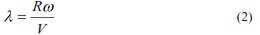
energy that is converted into mechanical energy by the wind turbine. It is a function of the tip speed ratio λ and depends on the blade pitch angle for pitch-controlled turbines. The tip speed ratio may be defined as the ratio of turbine blade linear speed and the wind speed
Substituting (2) in (1), we have:

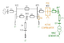
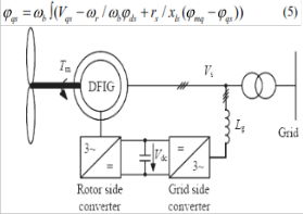
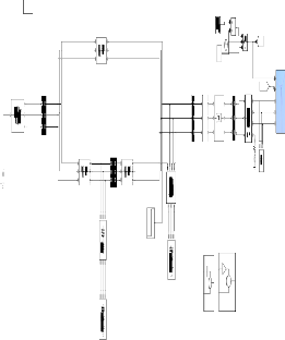
Fig. 1. Study case power system
The UPQC is controlled to regulate the WF terminal voltage, and to mitigate voltage fluctuations at the point of common coupling (PCC), caused by system load change and pulsating WF generated power, respectively. The voltage regulation at WF terminal is conducted using the UPQC series converter, by voltage injection ―in phase‖ with PCC voltage. On the other hand, the shunt converter is used to filter the WF generated power to prevent voltage fluctuations, requiring active and reactive power handling capability. The sharing of active power between converters is managed through the common DC link.
2 SYSTEM DESCRIPTION AND MODELING
A. System description:
Fig.1 depicts the power system under consideration in this study. The WF is composed by 36 wind turbines using squirrel cage induction generators, adding up to 21.6MW electric power. Each turbine has attached fixed reactive compensation capacitor banks (175kVAr), and is connected to the power grid via 630KVA
0.69/33kV transformer. This system is taken from [7], and represents a real case.
The ratio between short circuit power and rated WF power, give us an idea of the ―connection weakness‖. Thus considering that the value of short circuit power in MV6 is SSC≃ 120MV A this ratio can be calculated:
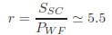
Values of r < 20 are considered as a ―weak grid‖ connection
[2].
B. Turbine rotor and associated disturbances model: The wind power developed by the turbine is given by the
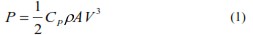
equation (1)
Where Cp is the Power Co-efficient, ρ is the air density in kg/m3,
A is the area of the turbine blades in m2 and
V is the wind velocity in m/sec.
The power coefficient Cp gives the fraction of the kinetic
The output torque of the wind turbine Tturbine is calculated by the following equation (4).
Where R is the radius of the wind turbine rotor (m)
There is a value of the tip speed ratio at which the power
coefficient is maximum [2]. Variable speed turbines can be made to capture this maximum energy in the wind by
operating them at a blade speed that gives the optimum tip speed ratio. This may be done by changing the speed of the turbine in proportion to the change in wind speed.
C. Model of induction generator:
A commonly used model for induction generator converting power from the wind to serve the electric grid is shown in figure 3.The stator of the wound rotor induction machine is connected to the low voltage balanced three- phase grid and the rotor side is fed via the back-to-back PWM voltage-source inverters with a common DC link. Grid side converter controls the power flow between the DC bus and the AC side and allows the system to be operated in sub-synchronous and super synchronous speed. The proper rotor excitation is provided by the machine side power converter and also it provides active and reactive power control on stator and rotor sides respectively by employing vector control. DFIG can be operated as a generator as well as a motor in both sub- Synchronous and super synchronous speeds, thus giving four possible operating modes. Only the two generating modes at sub-synchronous and super synchronous speeds are of interest for wind power generation. To exploit the advantages of variable speed operation, the tracking of optimum torque-speed curve is essential. Speed can be adjusted to the desired value by controlling torque. So, an approach of using active power set point from the instantaneous value of rotor speed and controlling the rotor current in stator flux-oriented reference frame to get the desired active power will result in obtaining the desired values of speed and torque according to the optimum torque speed curve. The reactive power set point can also be calculated from active power set point using a desired power factor.
In the stator flux-oriented reference frame, reactive power can be controlled by controlling the d-axis rotor current. In stator flux-oriented control, both stator and rotor
IJSER © 2011 http://www.ijser.org
International Journal of Scientific & Engineering Research Volume 2, Issue 12, December-2011 3
ISSN 2229-5518
quantities are transformed to a special reference frame that rotates at an angular frequency identical to the stator flux linkage space phasor with the real axis (x-axis) of the reference frame aligned to the stator flux vector. At steady state, the reference frame speed equals the synchronous speed. This model is called dynamic vectorized model.
The main variables of the machine in rotating
frame are flux linkages Ψqs , Ψds, Ψ’qr, Ψ’dr in state space form are derived and given in [8-9]. Substituting the conditions ω =ωr and Vqr=Vdr=0 in the flux linkage equation, we get:

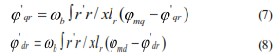
Fig.2 Wind turbine driven DFIG From Wind turbine driven DFIG
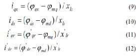
The currents can now be calculated

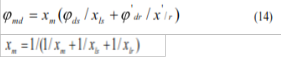
Solving equations (8-11), the Ψmq , Ψmd are obtained as
For maintaining proper flow of variables and for convenience of simulating, the above equations are separated into the q-axis, the d-axis and the rotor circuits. In the q-axis circuit, the Equations (6), (8), (10), (12) and (14) are used to calculate, Ψqs ,Ψ’qr ,iqs and i’qr respectively and Ψqs , iqs are used in the calculation of electromagnetic torque. In the q-axis circuit, the Equations (7), (9), (11), (13) and (15) are used to calculate, Ψds, Ψ׳dr , ids and i ׳dr respectively and Ψds, iqs are used in the calculation of electromagnetic torque. The rotor circuit makes use of the Ψds, iqs obtained from the q-axis circuit and Ψds, iqs obtained from the d-axis circuit and calculates
the electromagnetic torque using equation (16).The rotor circuit also takes the input mechanical torque values supplied to it and computes Wr/Wb from equation (16).

Now that we know Ψqs, iqs and Ψds, ids the electromagnetic torque can be calculated by;

The equation that governs the motion of rotor is obtained by equating the inertia torque to the accelerating torque [8]:
Expressed in per unit values, equation (13) becomes:

In equations (15) & (16), the flux linkages are 2-phase d-q axes rotating reference frame.
D. Dynamic compensator model
The dynamic compensation of voltage variations is performed by injecting voltage in series and active–reactive power in the MV6 (PCC) bus bar; this is accomplished by using an unified type compensator UPQC [9]. In Fig.3 we see the basic outline of this compensator; the bus bars and impedances numbering is referred to Fig.1.
The operation is based on the generation of three phase
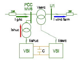
voltages, using electronic converters either voltage source type (VSI–Voltage Source Inverter) or current source type (CSI–Current Source Inverter). VSI converter is preferred because of lower DC link losses and faster response in the system than CSI [9]. The shunt converter of UPQC is responsible for injecting current at PCC, while the series converter generates voltages between PCC and U1, as illustrated in the phasor diagram of Fig.3. An important feature of this compensator is the operation of both VSI converters (series and shunt) sharing the same DC–bus, which enables the active power exchange between them.
IJSER © 2011 http://www.ijser.org
International Journal of Scientific & Engineering Research Volume 2, Issue 12, December-2011 4
ISSN 2229-5518
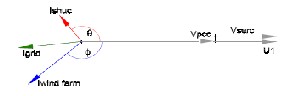
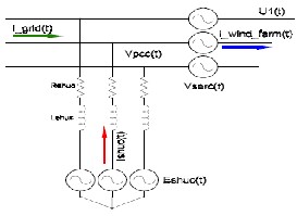
Fig.3 Block diagram and phasor diagram of UPQC
Fig. 4 Power stage compensator model on AC side
We have developed a simulation model for the UPQC
based on the ideas taken from [10]. Since switching control
of converters is out of the scope of this work, and
considering that higher order harmonics generated by VSI
converters are outside the bandwidth of significance in the
simulation study, the converters are modeled using ideal
controlled voltage sources. Fig.4 shows the adopted model
of power side of UPQC.
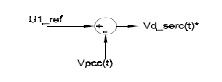
Fig.5 Series compensator controller
The control of the UPQC, will be implemented in a rotating
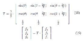
frame dq0 using Park’s transformation (eq.18-19)
―instantaneous power theory‖ based PLL has been
implemented [11].
Under balance steady-state conditions, voltage and currents
vectors in this synchronous reference frame are constant quantities. This feature is useful for analysis and decoupled
control.
3 UPQC CONTROL STRATEGY
The UPQC serial converter is controlled to maintain the WF terminal voltage at nominal value (see U1 bus-bar in Fig.4), thus compensating the PCC voltage variations. In this way, the voltage disturbances coming from the grid cannot spread to the WF facilities. As a side effect, this control action may increase the low voltage ride–through (LVRT) capability in the occurrence of voltage sags in the WF terminals [4], [9].
Fig.5 shows a block diagram of the series converter controller. The injected voltage is obtained subtracting the PCC voltage from the reference voltage, and is phase– aligned with the PCC voltage (see Fig.3).On the other hand, the shunt converter of UPQC is used to filter the active and reactive power pulsations generated by the WF. Thus, the power injected into the grid from the WF compensator set will be free from pulsations, which are the origin of voltage fluctuation that can propagate into the system. This task is achieved by appropriate electrical currents injection in PCC. Also, the regulation of the DC bus voltage has been assigned to this converter.
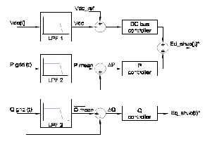
Fig.6 shows a block diagram of the shunt converter
controller. This controller generates both voltages
commands Ed shuC* and Eq shuC* based on power
fluctuations ∆P and ∆Q, respectively. Such deviations are calculated subtracting the mean power from the instantaneous power measured in PCC.
The mean values of active and reactive power are obtained
by low–pass filtering, and the bandwidth of such filters are
chosen so that the power fluctuation components selected for compensation, fall into the flicker band as stated in IEC61000-4-15 standard.
In turn, Ed shuC* also contains the control action for the DC–bus voltage loop. This control loop will not interact with the fluctuating power compensation, because its components are lower in frequency than the flicker–band.
Where fi=a,b,c represents either phase voltage or currents, and fi=d,q,0 represents that magnitudes transformed to the dqo space.
This transformation allows the alignment of a rotating reference frame with the positive sequence of the PCC voltages space vector. To accomplish this, a reference angle θ synchronized with the PCC positive sequence fundamental voltage space vector is calculated using a Phase Locked Loop (PLL) system. In this work, an
IJSER © 2011 http://www.ijser.org
Fig. 6 Shunt compensator controller
International Journal of Scientific & Engineering Research Volume 2, Issue 12, December-2011 5
ISSN 2229-5518
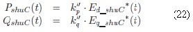
The powers PshuC and QshuC are calculated in the rotating reference frame, as follows:
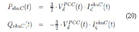
Ignoring PCC voltage variation, these equations can be written as follows.
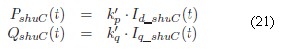
Taking in consideration that the shunt converter is based on a VSI, we need to generate adequate voltages to obtain the currents in (6). This is achieved using the VSI model proposed in [10], leading to a linear relationship between the generated power and the controller voltages. The resultant equations are:
4 SIMULATION RESULTS AND DISCUSSION
The model of the power system scheme illustrated in Fig.1, including the controllers with the control strategy detailed in section III, was implemented using Matlab/Simulink software.
Numerical simulations were performed to determine and then compensate voltage fluctuation due to wind power
variation, and voltage regulation problems due to a sudden load connection. The simulation was conducted with the following chronology:
• at t = 0.0‖ the simulation starts with the series converter
and the DC–bus voltage controllers in operation.
• at t = 0.5‖ the tower shadow effect starts;
• at t = 3.0‖ Q and P control loops(see Fig.6) are enabled;
• at t = 6.0‖ L3 load is connected.
• at t = 10.0‖ L3 load is disconnected
Discrete,
= 5e-005 powergui
P and Q control loops comprise proportional controllers, while DC–bus loop, a PI controller.
A aA
A A B B C C
Three-Phase
Series RLC Branch
aA A1 A2
Sine Wave
12
Constant
A A
Clock
Add
aA
Switch
A a
b
wind1
[Trip_WT1]
wind (m/s)
Ttrip
AA
BB
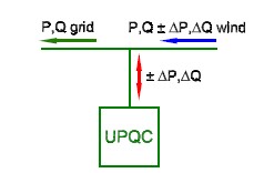
In summary, in the proposed strategy the UPQC can be
N B bB
C cC
bB B1 B2 B B bB B
c CC
seen as a ―power buffer‖, leveling the power injected into
Three-Phase
Three-Phase
cC C1 C2 C C cC
C n2
Wind Turbine 1
the power system grid. The Fig.7 illustrates a conceptual diagram of this mode of operation.
Programmable
Voltage Source
V-I Measurement2
A A Aa A A B B Bb B B C C Cc C C
Three-Phase UPQC
V-I Measurement
1 km line 1
B575_1 (575 V)
0.69/33e3
630KVA
170 kvar
Induction Generator
(PhasorType)
Three-Phase
Series RLC Branch2
Three-Phase Three-Phase
V-I MeasuremenSte1ries RLC Branch1
Three-Phase Breaker
Three-Phase
Series RLC Branch3
Timer
Three-Phase
Series RLC Load1
Three-Phase
Series RLC Load
Fig.7 Power Buffer
It must be remarked that the absence of an external DC source in the UPQC bus, forces to maintain zero–average power in the storage element installed in that bus. This is accomplished by a proper design of DC voltage controller. Also, it is necessary to note that the proposed strategy cannot be implemented using other CUPS devices like D– Statcom or DVR. The power buffer concept may be implemented using a DStatcom, but not using a DVR. On the other hand, voltage regulation during relatively large disturbances cannot be easily coped using reactive power only from DStatcom; in this case, a DVR device is more suitable.
Fig. 8 Simulink of a power system scheme illustrated in fig.
1
A. Compensation of voltage fluctuation
Simulation results for 0 < t < 6 are shown in Fig.9
At t = 0.5‖ begins the cyclical power pulsation produced by the tower shadow effect. As was mentioned, the tower shadow produces variation in torque, and hence in the active and reactive WF generated power. For nominal wind speed condition, the power fluctuation frequency is f =
3.4Hz, and the amplitude of the resulting voltage variation
at PCC, expressed as a percentage is:
This voltage fluctuation is seen in middle curve of Fig.9 for
0.5 < t < 3.
IJSER © 2011 http://www.ijser.org
International Journal of Scientific & Engineering Research Volume 2, Issue 12, December-2011 6
ISSN 2229-5518
In our case, we have considered a capacitor size C = 0.42 F. This high value can be easily obtained by using emerging technologies based capacitors, such as double–layer capacitors, also known as ultra capacitors.
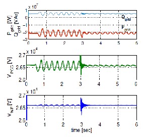
Fig. 9
Upper curve: active and reactive power demand at power
grid side. Middle curve: PCC voltage. Lower curve: WF
terminal voltages.
The fluctuation value is higher than the maximum allowed
by the IEC61000-4-15 standard [12]. This means that even in normal operation, the WF impacts negatively on the System Power Quality.
At t = 3.0‖ the active and reactive power pulsations are attenuated because the P and Q controllers come into action.
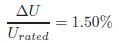
The amplitude of the PCC voltage fluctuation is reduced
from its original value of 1.6% (without compensation) to this new value:
This value agrees with IEC standard [12], since is lower than the specified permissible maximum limit, 0.5% at
3.4Hz.
In the lower curve of Fig.9 (c), WF terminal voltage
behavior is shown; the series converter action maintains WF terminal voltage constant, regardless of the PCC voltage behavior. The pulsation of active power and voltage at the UPQC DC–side, are shown in Fig.10
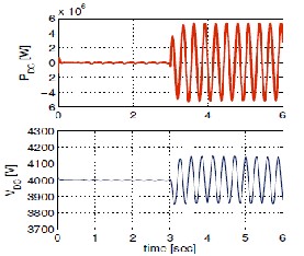
As can be observed in the upper curve, the series converter requires negligible power to operate, while the shunt converter demands a high instantaneous power level from the capacitor when compensating active power fluctuation. Compensation of reactive powers has no influence on the DC side power [13].
The DC-bus has voltage level limitations in accordance with the VSI’s operational characteristics. As the fluctuating active power is handled by the capacitor, its value needs to be selected so that the ―ripple‖ in the DC voltage is kept within a narrow range.
Fig. 10 Power and voltage of the capacitor in the DC-Bus
The compensation action can also be seen by observing the
trajectory of the power grid current space vector in the dq plane. It is necessary to note that the sign of the measured grid current is considered positive when it flows towards the park.
B. Voltage regulation
As been stated in Secc.III, the UPQC is also operated to maintain the WF terminal voltage constant, rejecting PCC voltage variations, due to events like sudden connection/disconnection of loads, power system faults, etc. A sudden connection of load is performed at t = 6‖, by closing L3 switch (SW) in Fig.1. This load is rated at PL3 =
9.2MW and Q L3 = 9.25MW. Such load is then disconnected
at t = 10‖.
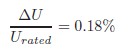
Fig.11 shows the PCC and WF terminal voltages, and series injected voltage at ―a‖ phase. In this figure is clearly seen a sudden change in PCC voltage, while WF terminal voltage remains almost constant due to series converter action.
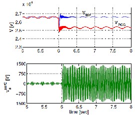
Fig. 11 Voltage at Wind Farm, at PCC and Series injected
voltage at ―a‖ phase
IJSER © 2011 http://www.ijser.org
International Journal of Scientific & Engineering Research Volume 2, Issue 12, December-2011 7
ISSN 2229-5518
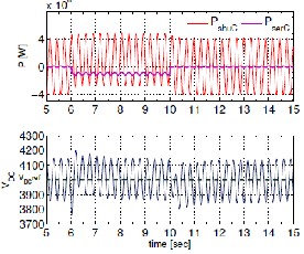
In the upper curve of Fig.12 seen shunt and series converter active–power behavior. The mean power injected (absorbed) by series converter is absorbed (injected) by shunt converter, because of DC voltage regulation loop action (Fig.6). So, the step in series converter active power is the same but opposite sign, which is shunt converter power. Fig.12 (b) also shows DC–bus voltage, and is clearly seen the VDC control action.
Fig.12 Shunt and series converter active -power and DC bus voltage
5 CONCLUSION
In this paper, a new compensation strategy implemented using an UPQC type compensator was presented, to connect SCIG based wind farms to weak distribution power grid. The proposed compensation scheme enhances the system power quality, exploiting fully DC–bus energy storage and active power sharing between UPQC converters, features not present in DVR and D–Statcom compensators. The simulation results show a good performance in the rejection of power fluctuation due to
―tower shadow effect‖ and the regulation of voltage due to a sudden load connection. So, the effectiveness of the proposed compensation approach is demonstrated in the study case. In future work, performance comparison between different compensator types will be made.
REFERENCES
[1] M.F. Farias, P.E. Battaiotto and M.G. Cendoya ―Wind Farm to
Weak-Grid Connection using UPQC Custom Power Device‖ ; IEEE
2010. p.p.1745-1750.
[2] B.Chitti Babu , K.B.Mohanty, ―Doubly-Fed Induction Generator for Variable Speed Wind Energy Conversion Systems- Modeling & Simulation ―International Journal of Computer and Electrical Engineering, February, 2010. P.P. 1793-8163.
[3] M.P. P´alsson, K. Uhlen, J.O.G. Tande. ―Large-scale Wind Power
Integration and Voltage Stability Limits in Regional Networks‖;
IEEE 2002. p.p. 762–769
[4] P. Ledesma, J. Usaola, J.L. Rodriguez ―Transient stability of a fixed speed wind farm‖ Renewable Energy 28, 2003 pp.1341–1355
[5] P. Rosas ―Dynamic influences of wind power on the power system‖.
Technical report RISØR-1408. Ørsted Institute. March 2003.
[6] R.C. Dugan, M.F. McGranahan, S. Santoso, H.W. Beaty ―Electrical
Power Systems Quality‖ 2nd Edition McGraw–Hill, 2002. ISBN 0-
07-138622-X
[7] P. Kundur ―Power System Stability and Control‖ McGraw-Hill,
1994. ISBN 0-07-035958-X
[8] N. G. Hingorani y L. Gyugyi. ―Understanding FACTS‖. IEEE Press;
2000.
[9] Z. Saad-Saoud, M.L. Lisboa, J.B. Ekanayake, N. Jenkins and G.
Strbac ―Application of STATCOM’s to wind farms‖ IEE Proc. Gen. Trans. Distrib. vol. 145, No. 5; Sept. 1998
[10] T. Burton, D. Sharpe, N. Jenkins, E. Bossanyi ―Wind Energy
Handbook‖ John Wiley & Sons, 2001. ISBN 0-471-48997-2.
[11] A. Ghosh, G. Ledwich ―Power Quality Enhancement Using Custom
Power Devices‖ Kluwer Academic Publisher, 2002. ISBN 1-4020-
7180-9
[12] C. Schauder, H. Mehta ―Vector analysis and control of advanced static VAR compensators‖ IEE PROCEEDINGS-C, Vol.140, No.4, July 1993.
[13] E.M. Sasso, G.G. Sotelo, A.A. Ferreira, E.H. Watanabe, M. Aredes, P.G. Barbosa, ―Investigac¸ ˜ao dos Modelos de Circuitos de Sincronismo Trif´asicos Baseados na Teoria das Potˆencias Real e Imagin´aria Instant ˆaneas (p–PLL e q–PLL)‖, In: Proc. (CDROM) of the CBA 2002 – XIV Congresso Brasileiro de Automtica, pp. 480-485, Natal RN, Brasil, 1-4, Sep. 2002
[14] International Electrotechnical Commission ‖INTERNATIONAL
STANDARD IEC 61000-4-15: Electromagnetic compatibility (EMC) Part 4: Testing and measurement techniques Section 15: Flickermeter Functional and design specifications.‖ Edition 1.1 2003
[15] H. Akagi, E. H. Watanabe, M. Aredes ―Instantaneous power theory
and applications to power conditioning‖, John Wiley & Sons, 2007.
978-0-470-10761-4.
IJSER © 2011 http://www.ijser.org