International Journal of Scientific & Engineering Research, Volume 5, Issue 7, July-2014 654
ISSN 2229-5518
Power Flow Control and Voltage Management of Distribution Grid Supported With Renewable Generation
1Mr. Pradeep Maheshwari, 2Dr. Sushma Gupta
1,2Electrical Engg. Department
MANIT, Bhopal
Abstract: In late years, hybrid solar wind energy has become one of the most significant and promising sources of renewable energy, which requires an additional transmission capability and safer means of maintaining system voltages and reliability. W ith a large number of distributed generation access, the impact of distributed generations of the grids’ security, reliability and stability cannot be ignored. The purpose of this work is the development of a solar-wind hybrid power system that harnesses the renewable energies in the Sun and W ind to generate electricity. This report makes the hybrid distribution system, solar generation, asynchronous wind turbine and the micro-grid model based on Matlab/Simulink simulation platform.
Keywords: Renewable Energy, PV-solar, W ind Generation, W ind Turbine, Hybrid generation, Micro-grid, Distribution Grid.
Energy is playing an important role in human and economic development. Ace of the driving forces of social and economic development and a basic requirement of the nation is energy. Most of the energy production methods are one-way, which cries for an alteration of form for the push. In parallel to developing technology, demand for more energy makes us seek new energy sources. In parallel to developing technology, demand for more energy makes us seek new energy sources. Researches for renewable energies have been initiated first for wind power and then for solar power. The efficiency of solar power conversion systems is ca. 18%, whilst that of wind power is ca. 55%.
Wen Shao, Buhan Zhang, Chenxiong Mao, Yizhe Chen, Biao Mao, Yi Chen, Jie Zeng, Xun Chen [1], presented With a large number of distributed generations’ access, the impact of distributed generations of the grids ’ security and stability cannot be ignored. The micro-grid is a good solution to the approach. This paper makes the asynchronous wind turbine and the microgrid model based on Matlab/Simulink simulation platform.
Arjun A. K., Athul S., Mohamed Ayub, Neethu Ramesh, and Anith Krishnan [2], presented one of the primary needs of socioeconomic development in any nation in the creation is the provision of reliable electricity supply systems with lower carbon footprint levels. The aim of this study is the maturation of a Solar-Wind hybrid Power system that harnesses the renewable energies in the Sun and Wind to generate electricity.
Ghassan Halasa [3], presented the electrical power generation using solar- and wind-energy for the country of
Jordan. Presently, with the oil prices are on the ascent, the cost of electrical power output is really gamey. The prospect of a large wind and solar hybrid power production is being explored. Sights are chosen to produce electricity using, the wind in the Mountains.
Ugur Fesli, Raif BAYIR, Mahmut OZER [4], presented the
most important application field of this search is renewable
energy resources. Wind and solar energy have being popular ones owing to abundant, ease of availability and convertibility to the electric energy. This work covers realization of a hybrid renewable energy system for a domestic application, which runs under a microcontroller to utilize the solar and wind power.
Chaitanya Marisarla, K. Ravi Kumar [5], presented paper
proposes a hybrid energy system consisting of wind, photovoltaic and fuel cell. Battery storage is designed to supply continuous power and to provide the deficit power when the combined wind and photovoltaic sources cannot meet the net load demand.
Ch. Breyer, S. Rieke, M. Sterner, J. Schmid [6], presented Solar and wind resources are abundantly available on earth, enabling the usage of photovoltaic (PV) and wind energy technologies on a large plate in most neighborhoods in the Earth. This paper aims at investigating a global energy supply scenario based of PV and wind power supported by an appropriate energy.
Saeed Jahdi, Loi Lei Lai, Daneil Nankoo, [7] given the role of Renewable Energy power sources is the best possible solution today to reduce the increased danger of global warming and the most important type of renewable is Wind and Solar energies which are the most effective. The green power generation resources use power generators in
IJSER © 2014 http://www.ijser.org
International Journal of Scientific & Engineering Research, Volume 5, Issue 7, July-2014 655
ISSN 2229-5518
Distributed Generation (DGs) sauces that are in direct relation with the function of micro capacity power generating units of power arrangement that are installed in distribution level of power systems or all segments that loads and energy consumers are placed.
Balamurugan T., Manoharan S., [8] reported the Optimal Power Flow Management control for Grid Connected Photovoltaic/Wind turbine/ Diesel generator (GCPWD) Hybrid System with hybrid storage system. The energy system having a photo voltaic (PV) panel, wind turbine (WT) and diesel generator (DG) for continuous power flow management. A diesel generator is added to ensure uninterrupted power supply due to the discontinuous nature of solar and wind resources. The developed Grid Connected Photovoltaic/Wind turbine/ Diesel generator (GCPWD) Hybrid System has been used to provide continuous power to the AC/DC loads. A Grid Connected Photovoltaic/Wind turbine/ Diesel generator (GCPWD) hybrid systems three power sources (PV, wind turbine and diesel generator) and two power sink (AC&DC loads). Boucetta. Abdallah, Labed. Djamel [9], presented an effective use of renewable energy attracts a great deal of attention globally to cope with the environmental and resource problems, especially, to reduce CO2 emission, an inappropriate application of distributed generators can be a cause of insecure power supply for example. However, these renewable energy sources suffer from some deficiencies when used as standalone energy sources. The power generated by WT and PV systems is highly dependent on weather conditions. Natural variations in wind speed and sunlight causes power fluctuations in WT and PV systems, respectively. In addition, it is difficult to store the power generated by a PV or WT system for future use. In This paper deals with power control of a wind and solar hybrid generation system for interconnected operation with an electric distribution system.
Wind energy is the kinetic energy associated with the motion of atmospheric air. It has been practiced for hundreds of years for sailing, grinding grain and for irrigation. Current of air energy systems convert this kinetic energy into more useful patterns of force. Current of air energy systems for irrigation and milling have been in use since ancient times and at the outset of the 20th century it is being applied to generate electric power. Windmills for water pumping have been installed in many countries, particularly in the rural areas. Wind turbines transform the energy in the wind into mechanical force, which can then be applied directly for grinding, etc. or further converting to electric power to get electricity. Wind turbines can be employed individually or in clusters called ’wind farms [7,
9, 10].
Solar energy is directly from the Sun. It is renewable, inexhaustible and environmental pollution free. Solar charged battery systems provide power supply for a complete 24 hours a day regardless of bad conditions. By taking the appropriate technology for the concerned geographical location, we can take out a heavy measure of power from solar radiations. Moreover solar energy is required to be the most promising alternate source of vitality. The global search and the rise in the price of conventional fossil fuel is creating supply-demand of the electricity product almost impossible particularly in some remote regions. Generators, which are frequently employed as an option to conventional power supply schemes, are known to be run alone during certain hours of the day, and the cost of felling them is more and more getting difficult if they are to be used for commercial uses. There is a growing awareness that renewable energy such as photovoltaic system and Wind power have an important role to play in order to save the situation [5, 9]. Hybrid power system consist of a combination of renewable energy source such as wind generators, solar, etc. of charge, batteries and provide power to fulfil the energy demand, taking the local geography and other details of the place of initiation. These types of systems are not plugged in to the main utility power system. They are too utilized in stand-alone applications and work independently and reliably. The best applications for these types of systems are in remote situations, such as rural villages, in telecommunications, etc. The importance of hybrid systems has grown as they appear to be the correct answer for a clean and distributed energy production. As an initial step towards the development, we shall extend the street lighting around the main blocks of the college, which presently draw power from the electricity board supply lines.
The speedy development of solar and wind powers is due in part to favorable global political climate towards these energies, efforts to reduce carbon dioxide (CO2) and greenhouse gases (GHG) and other power plant pollutants, global awareness of mood changes, and the urgency to acquire renewable energy sources. Other ingredients such as lucrative tax incentives and legislation mandating national renewable energy standards have accelerated the march towards solar and wind energies. For instance in the US, some nations have enacted “renewable portfolio standard (RPS)” legal philosophy that calls for utilities to sell a certain percent of the energy from sustainable energy sources within reasonable stipulated times. Even though Europe and North America have the largest installed capacity of wind turbine capacity, China, India, and developing world bear the largest potential for wind power [5, 7, 9].
IJSER © 2014 http://www.ijser.org
International Journal of Scientific & Engineering Research, Volume 5, Issue 7, July-2014 656
ISSN 2229-5518
The work reported in this work has been carried out with the objective of studying the effect of voltages and power flow capability enhancement in power system.
The objectives of the work are as given below:
• The main focus is given to modelling,
validation and control for PV-solar, and wind
generation with grid-connected systems.
• The goal of this work is to model a multi-
source alternative DG system consisting of
wind turbine(s), PV arrays, and to manage the voltage profile and power flows among the different energy resources in the system.
• Comparing simulation results between
different resources connected to the grid.
• Energy management and control of the hybrid
system.
• The site is abundant in renewable energy and
the hybrid nature increases the reliability and reduces the dependence on one single source.
PV is the most promising materials in nowadays; it is one of the commonly used renewable energy sources to the grid power system. Solar panels are the medium to convert solar power into the electrical power. Solar panels can convert the energy directly or heat the water with the induced energy [7]. PV (Photo-voltaic) cells are made up from semiconductor structures as in the computer technologies. A sun beam is absorbed with this material and electrons are emitted from the atoms that they are bounded, this release activates a current. Photovoltaic is known as the process between beam absorbed and the electricity induced. With a common principle and individual components, solar power is converted into the electric power [4-7].
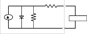
Solar Cell
Rs
+
Fig. 1: Equivalent circuit diagram of a solar PV cell [7]
The photovoltaic cell output voltage is basically a function of the photocurrent which is mainly determined by load current depending on the solar irradiation level during the operation [6, 7].
Vc = (A*k*Tc/e) ln((Iph+I0-Ic)/I0) - Rs*Ic (1) The symbols used are described below
Vc: cell output voltage, V.
Tc: reference cell operating temperature (20 °C).
Rs: series resistance of cell (0.001 Ω).
Iph: photocurrent, function of irradiation level and junction temperature (5 A).
I0: reverse saturation current of the diode (2*10^-4 A).
Ic: cell output current, A.
k: Boltzmann constant (1.38 × 10^-23 J/K).
e: electron charge (1.602 × 10^-19 C).
Wind power systems convert the kinetic energy of the wind into other forms of energy such as electricity. Although wind energy conversion is relatively simple in concept, turbine design can be rather complex. Most commercially available wind turbine uses a horizontal – axis configuration with two or three blades, a drive train, including a gear box and a generator and a tower to hold the rotor. Typical sizes for a wind turbine range from 200-
750 KW, with electricity produce within a specific scope of
wind velocity. Wind energy involves the conversion of the
kinetic energy present in the wind into mechanical energy [1]. The extraction of the wind’s kinetic energy is accomplished by a blade-rotor system. The mechanical energy which is in a form of rotation of a shaft connected to the rotor system is then converted to electricity using a generator. Normally a gearbox (planetary or parallel design) is employed between the main shaft and the generator to step-up the shaft’s speed to the electric generator [1]. As applied to the solar resource, the wind energy available around the planet at any instant is quite vast. The doubly fed induction machine is the most widely machine in these days. The induction machine can be used as a generator or motor. With the use of power of the wind, wind turbines produce electricity to drive an electrical generator. Usually wind passes over the blades, generating lift and exerting a turning force. Inside the nacelle the rotating blades turn a shaft, then goes into a gearbox. The
Rsh
DC equivalent circuit
Load
-
gearbox helps in increasing the rotational speed for the operation of the generator and utilizes magnetic fields to convert the rotational energy into electrical energy, then the output electrical power goes to a transformer, which converts the electricity to the appropriate voltage for the
IJSER © 2014 http://www.ijser.org
International Journal of Scientific & Engineering Research, Volume 5, Issue 7, July-2014 657
ISSN 2229-5518
power collection system. A wind turbine extracts kinetic
energy from the swept area of the blades [1,5, 9]. With the use of power of the wind, wind turbines produce electricity to drive an electrical generator. Usually wind passes over the blades, generating lift and exerting a turning force.
Pi =
Qi =
n
∑ ![]() Vi
Vi ![]() Vk
Vk ![]() Yik
Yik ![]()
k =1
n
∑ ![]() Vi
Vi ![]() Vk
Vk ![]() Yik
Yik ![]()
k =1
cos(δi − δ k + θik ) = PGi − PDi
sin(δi − δ k + θik ) = QGi − QDi
(9 ) (10 )
Inside the nacelle the rotating blades turn a shaft then goes into a gearbox. The gearbox helps in increasing the rotational speed of the operation of the generator and
The basic power balance equations:
PGi = PDi + PL
Q = Q + Q
(11) (12 )
utilizes magnetic fields to convert the rotational energy into
electrical energy. Then the output electrical power goes to a
transformer, which converts the electricity to the
Gi Di L
The power flow equations considering losses with Hybrid
generations for the practical distribution grid are given as:
appropriate voltage for the power collection system. A
wind turbine extracts kinetic energy from the swept area of
Pi + PHybrid
Q + Q
= PDi + PL
= Q + Q
(13) (14)
the blades [1, 5, 9].
The power contained in the wind is given by the kinetic
energy of the flowing air mass per unit time [5, 7, 8]. The equation for the power contained in the wind can then be
i Hybrid Di L
The PV-solar is the active power (PPV-solar) source only; so
Qhybrid=0.
written as:
P + P
= P + P
(15)
![]()
P = 1 (air mass per unit time) * (V )2
(2)
i PV Di L
Qi = QDi + QL
(16)
air
![]()
= 1
2
( ρ AV
) * (V )2
∞
(3)
n
∑ ![]() Vi
Vi ![]() Vk
Vk ![]() Yik
Yik ![]()
k =1
cos(δi − δk + θik ) + PPV = PDi + PL
(17)
2 ∞ ∞![]()
= 1 ρ A(V )3
(4)
n
∑ ![]() Vi
Vi ![]() Vk
Vk ![]() Yik
Yik ![]()
k =1
sin(δi − δk + θik ) = QDi + QL
(18)
2 ∞
The wind generation is the source of both active powers
Although above equations describe the availability of
power in the wind, power transferred to the wind turbine
(PW) and reactive power (QW).
rotor is reduced by the power coefficient Cp.
P
Pi + PW
Qi + QW
= PDi + PL
= QDi + QL
(19) (20)
C p =
wind turbine
![]()
Pair
(5)
n
∑ ![]() Vi
Vi ![]() Vk
Vk
k =1
![]() Yik
Yik ![]()
cos(δi − δ k + θik ) + PW = PDi + PL
(21)
Pwind turbine
= C p
* Pair
(6)
n
∑ ![]() Vi
Vi ![]() Vk
Vk
k =1
![]() Yik
Yik ![]()
sin(δi − δ k + θik ) + QW = QDi + QL
(22)
The problem formulation for total power flow management and voltage enhancement with hybrid (Wind and PV-solar) generation. To determine the maximum power flow that can flow from a specific set of generators in the source area
The final power flow equations with hybrid wind and pv- solar in the distribution system are:
n
∑ ![]() Vi
Vi ![]() Vk
Vk ![]() Yik
Yik ![]() cos(δi − δk + θik ) + PPV + PW = PDi + PL (23)
cos(δi − δk + θik ) + PPV + PW = PDi + PL (23)
k =1
n
to load in the sink area within real and reactive power
generation limits, line flow limits, voltage limits, and
∑ ![]() Vi
Vi ![]() Vk
Vk ![]() Yik
Yik ![]() sin(δi − δk + θik ) + QW = QDi + QL
sin(δi − δk + θik ) + QW = QDi + QL
k =1
n
(24)
operating limits. In order to analyze the operation of the
system a model has been developed which takes into
account the characteristics and efficiencies of the devices
and performs all necessary internal power loops.
∑ ![]() Vi
Vi ![]() Vk
Vk ![]() Yik
Yik ![]() cos(δi − δ k + θik ) + PPV + PW − PDi − PL = 0 (25)
cos(δi − δ k + θik ) + PPV + PW − PDi − PL = 0 (25)
k =1
n
∑ ![]() Vi
Vi ![]() Vk
Vk ![]() Yik
Yik ![]() sin(δi − δ k + θik ) + QW − QDi − QL = 0 (26)
sin(δi − δ k + θik ) + QW − QDi − QL = 0 (26)
k =1
The well known basic load flow equations are:
min
i
min
≤ Pi ≤ Pmax
max
(27)
Si =
Pi + jQi =Vi .Ii*
(7)
Qi ≤ Qi ≤ Pi
(28)
min ≤ Vi ≤ Vmax (29)
= Vi
n n
Y *V * =
![]()
Vi ![]() Vk
Vk ![]() Yik
Yik ![]()
∠(δi − δk + θik ) (8)
Vi i
∑ ik k ∑
min ≤ P
≤ Pmax (30)
k =1
k =1
PPV
PV PV
Resolving into the real and imaginary parts, then the power flow equations with-out Hybrid generations are given as:
min
W
≤ PW ≤ Pmax
(31)
IJSER © 2014 http://www.ijser.org
International Journal of Scientific & Engineering Research, Volume 5, Issue 7, July-2014 658
ISSN 2229-5518
min
W
Where,
≤ PW ≤ Pmax
(32)
Now, after installing renewable distributed generation voltage is:
Pi, Qi : real and reactive power flow at bus i. PDi, QDi : real and reactive loads at bus i.
Vi , Vk : voltage magnitudes at bus i and k.
PPV: real power of PV-solar.
V3 =V2 +Vr ; So, V3 > V2
Hence
|V1||V3|
PW: real power of wind generation.
QW: reactive power of wind generation.
N: total number of buses.
δi , δk : voltage angles of bus i and k.![]()
P′ =
Q′ =
sinδ (36)
X
![]()
|V1||V3 | (1 − sinδ) (37)
X
Yik : magnitude of the ikth element in bus admittance
matrix.
That is, P′
> P ; and Q′ > Q
θik : angle of the ikth element in bus admittance matrix.
For example the simple distribution system is analyzed, let
the voltage magnitude and angles areV1, V2 and δ1 , δ2 as
shown.
The active power, reactive power transfer and voltage
enhanced after installing renewable distributed
generation in the distribution system.

The general schematic diagram of the planned hybrid system is shown in Fig. 4. The system consists of turbine generators system, electrical phenomenon. The ability provided to the load is that the add of output powers from turbine generator and PV system. For this different cases are given as:
Fig. 2: Representation of simple distribution system
The active and reactive power transfer before installing renewable distributed generation from one to another of the line is given by:
Let δ = δ1 − δ2 (33)![]()
P = |V1 ||V2 | sinδ (34)
X
PV Solar
Wind
Generation
C o nt ro lle r
Storage
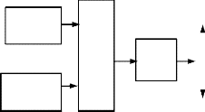
To Loads
![]()
![]()
![]()
![]()
To Loads
Grid
![]()
Q = |V1 ||V2 | (1 − sinδ) (35)
X
By the above equations we can say that, active and reactive
power transfer mainly depends on voltage magnitude and
angles.![]()
Fig 4: The schematic of the hybrid system
5.1 Case-1: Grid With-out Renewable Generation
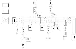
The modeling of grid With-out renewable Generation is given below.The distribution grid connected with grid supply and different loads has been proposed.

Measurements
Discrete,
Ts = 5e-005 s.
powergui
apartment building1
RL1
R10
RLC
RL2
R11
A
A A
B
a Aa c
A B B C
C
Aa Aa
b
N B Bb
C C n2 C c
Bb Bb
C c C c
10kv
Three-Phase M0
M1 M2
Transformer
(Two Windings)
r
R1 R9
RL3
R6 R8
RL5
RL
Fig. 3: Representation of simple distribution system with
renewable distributed generation (DG)
R
R7
A Subsystem1
The active and reactive power transfer after installing renewable distributed generation (DG) from one to another
B
C
Three-Phase
Series RLC Load1
group of 4R
of the line is given by:
Fig 5: The micro-grid simulation diagram With-out
renewable Generation
IJSER © 2014 http://www.ijser.org
International Journal of Scientific & Engineering Research, Volume 5, Issue 7, July-2014 659
ISSN 2229-5518
350
Votage profile of system with-out renewable generation
Pul se
Generator
Pul se
Generator1
Pul se
Generator3
300
250
200
150
+
- v
1000 Constant
Di spl ay2
Scope2
Di spl ay4
IGBT/Diode
+ v
-
/Diode1
Diode2 a
1
b
2
c
3
100
IGBT/Diode3
BT/Diode4 I iode5
50 Pul se
Pul se
Pul se
Generator4
Generator5 Generator6
0
0 0.05 0.1 0.15 0.2 0.25 0.3 0.35 0.4 0.45 0.5
Time (sec)
Fig 9: PV Solar simulation diagram
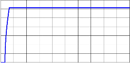
Fig 6: Voltage profile of system without renewable
Generation
1 w_Wind
4
x 10

15
Active Power profile without renewable generation
2 -K-
Bus M0
Bus M1
Bus M2
10
-C-
Switch
Tm
Gain
w_ASM
5
0
0 0.05 0.1 0.15 0.2 0.25 0.3 0.35 0.4 0.45 0.5
Time (sec)
Fig 7: Active power profile of system without renewable
Generation
Reactive power profile without renewable Generation
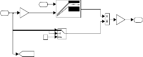
Fig 10: Wind Turbine simulation diagram
5.2 Case-2: Grid with Wind Generation
The modeling of grid with wind Generation is given below. The wind turbine’s rated capability, voltage, and wind speed are 75kVA, 400V and 10m/s severally. The output
3500
3000
2500
2000
1500
1000
500
0

0 0.05 0.1 0.15 0.2 0.25 0.3 0.35 0.4 0.45 0.5
Time (sec)
port of the asynchronous turbine is in parallel with a
capacitance for the employment of reactive power compensation.
Fig 8: Reactive power profile of system without renewable
Generation
Table 1: Voltages and Power of grid Without renewable
Generation
Fig 11: The micro-grid simulation diagram with Wind generation
350
300
250
200
150
100
50
0
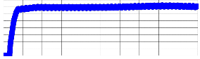
Voltage profile with wind Generation
0 0.05 0.1 0.15 0.2 0.25 0.3 0.35 0.4 0.45 0.5
Time (sec)
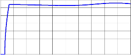
Fig 12: Voltage profile of system with wind Generation
IJSER © 2014 http://www.ijser.org
International Journal of Scientific & Engineering Research, Volume 5, Issue 7, July-2014 660
ISSN 2229-5518

350
5
x 10
2.5
2
1.5
Active power profile with wind Generation
M0
M1
M2
Bus | With PV-solar Generation | ||
Bus | V (volts) | P (kw) | Q (kvar) |
M0 | 335.2 | 563.9 | 515.9 |
M1 | 335.2 | 527.8 | 516.5 |
M2 | 335.2 | 539 | 516.8 |
Voltage profile of system with PV Generation
300
250
200
150
100
50
0
Fig
16:
0 0.05
5
x 10
8
1
7
Ac tive power profile with PV Generation
6
0.5
5
4
0 M0
0 0.05 0.1 0.15 0.2 0.25 0.3 0.35 0.4 0.45 0.5
M1
Time (sec) 3 M2
Fig 13: Active power profile of system with wind
Generation
2
1
0
0 0.05 0.1 0.15 0.2 0.25 0.3 0.35 0.4 0.45 0.5
Time (s ec )
4
x 10
9
Reactive power profile with wind Generation
Fig 17: Active power profile of system with PV Generation
8
7
M0
6 M1
M2
5
4
5
x 10
12
10
8
Reactive power profile with PV Generation
M0
M1
M2
3 6
2
4
1
0
0 0.05 0.1 0.15 0.2 0.25 0.3 0.35 0.4 0.45 0.5
Time (sec)
2
0
0 0.05 0.1 0.15 0.2 0.25 0.3 0.35 0.4 0.45 0.5
Fig 14: Reactive power profile of system with wind
Generation
Table 2: Voltages and Power of grid with wind Generation
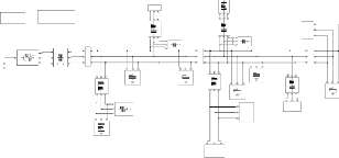
5.3 Case-3: Grid with PV solar
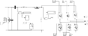
The modeling of grid With PV solar Generation is given below. The proposed system which is a connected with a
300 W and 125 DC voltage solar is used for simulations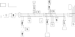
system at bus M2. This system consists with AC inverter to system with a DC photovoltaic circuit system connected with a converter and an inverter to the system.
Time (sec)
Fig 18: Reactive power profile of system with PV Generation
Table 3: Voltages and Power of grid With PV-solar
Generation
apartment bui l di ng1
RLC
Discrete,
Ts = 5e-005 s. powergui
SYST EM MEASUREMENT
Measurement
RL1
R10
A
RL2
R11
A B
PV sol ar
a1 b1 c1
5.4 Case-4: Grid with Hybrid Wind (constant) and
A A a Aa
N B B b
C C c C c
10kv
B C
C
Aa Aa
b Bb
C c C c
M1 M2
The modeling of grid with hybrid Generation is given
below. The hybrid system operation under the wind
Three-Phase M0
Transformer
(Two Windings)
RL
R1
R A
B C
R9
RL3
R8
R6
RL5
bui l di ng 2
R7
generation and solar generation condition has been reported.
Three-Phase
Series RLC Load1
group of 4R
Fig 15: The micro-grid simulation diagram with PV solar
IJSER © 2014 http://www.ijser.org
International Journal of Scientific & Engineering Research, Volume 5, Issue 7, July-2014 661

ISSN 2229-5518
Discrete,
Ts = 5e-005 s.
SYST EM
M EASUREM ENT
apartm ent bui l di ng1
RLC
PV sol ar
360
Voltage With-out
powergui
M easurem ent
RL1
R10
A
RL2
a1
b1
R11 c1
A
B
340
Hybrid
A a Aa
N B B b Bb
B C
C
Aa Aa
Bb Bb
320
Generation
A
C C c C c
10kv
C c C c
M1 M2
Three-Phase M0
Transformer
(Two Windings)
R1
RL
R A
B C
R9
RL3
R8
R6
a b
RL5
bui l di ng 2
R7
300
280
Voltage With
Wind Generation
Three-Phase
Series RLC Load1
c 1
wi nd turbi ne
group of 4R
Fig 19: The micro-grid simulation diagram with Hybrid
(wind and solar) Generation
800
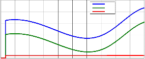
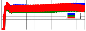
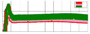
Fig 23: The Voltages in different cases
400
350
300
250
200
150
100
50
0
Voltage profile with hybrid Generation
0 0. 05 0. 1 0. 15 0. 2 0. 25 0. 3 0. 35 0. 4 0. 45 0. 5
Time (s ec )
600
400
200
Voltage With- out Hybrid Generation
Voltage With
Wind
Fig 20: Voltage profile of system with hybrid Generation
0
M0 M1 M2
Generation
5
x 10
9
Active power profile with hybrid Generation
8
7
6
5
M0
4 M1
M2
3
2
1
0
0 0.05 0.1 0.15 0.2 0.25 0.3 0.35 0.4 0.45 0.5
Time (s ec )
Fig 21: Active power profile of system with hybrid
Generation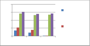
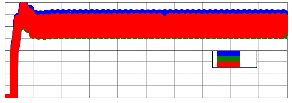
Fig 24: The Active power in different cases
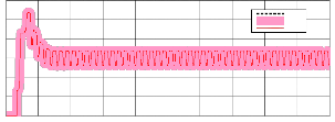
5.5 Case-5: Grid with Hybrid Variable Wind and Solar
The basic wind velocity rate is 10m/s, the wind speed waveform combined with the basic wind and also the impulse wind is shown in Fig. 27, the Impulse wind with a maximum wind velocity 5m/s starts at time 0.1s, ends at time 0.3s. The wind speed waveform combined with the basic wind and the ramp wind is shown in Fig. 26, the ramp
5
x 10
12
10
8
6
4
2
Reactive power profile with hybrid Generation
M0
M1
M2
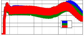
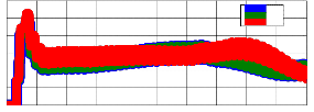
wind velocity slope 25m/s starts at time 0.1s, ends at time
0.3s. The voltage and power waveforms of the varable wind speed turbine are shown in Fig. 28, Fig. 29 and Fig. 30. The real and reactive power has varied smoothly compared to wind speed changes. The results for the impulse wind speed is given.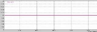
0
0 0.05 0.1 0.15 0.2 0.25 0.3 0.35 0.4 0.45 0.5
Time (sec)
Fig 22: Reactive power profile of system with hybrid
Generation
Table 4: Voltages and Power of grid With Hybrid
Generation
With Hybrid Generation
Bus
V (volts) P (kw) Q (kvar)
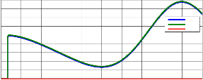
Fig. 25. Basic (constant) wind speed waveform
M0 354.8 608.2 387.2
M1 354.8 557.8 388.2
M2 354.8 570.5 473.1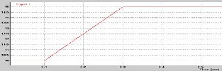
Fig. 26. Ramped wind speed waveform
IJSER © 2014 http://www.ijser.org
International Journal of Scientific & Engineering Research, Volume 5, Issue 7, July-2014 662
ISSN 2229-5518
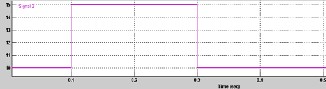
Fig 30: Reactive power profile of system with hybrid variable wind and solar Generation
400
350
300
250
200
150
100
50
0
Fig 27: Impuse wind speed waveform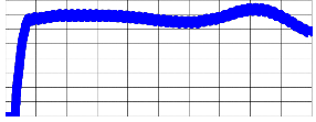
Voltage profile with hybrid variable wind and solar Generation
0 0.05 0.1 0.15 0.2 0.25 0.3 0.35 0.4 0.45 0.5
Time (sec)
Feasibility study on power management of grid-connected wind/PV hybrid generation. The modeling and simulation study was meted out supported MATLAB. The simulation results showed the wonderful performance of the wind/PV hybrid management in response to severe changes in wind speed.
1. The modelling of hybrid generation, system grid for power system configuration is done in MATLAB/SIMULINK environment. The present work mainly includes the grid tied operation of
Fig 28: Voltage profile of system with hybrid variable wind
and solar Generation
5
hybrid generation.
2. The result shows the voltage improved from 306.4
volts to 325.9 volts with wind generation and 335.2
x 10
9
8
7
6
5
4
3
2
1
Active power profile with hybrid variable wind and solar Generation
M0
M1
M2
volts with solar PV, which are given in fig. 11.
3. The active power flow also enhanced from 142.7
KW to 216.5 KW with wind generation, in different cases which are given in fig. 12.
4. The hybrid generation with a grid can provide a
reliable, high quality and more efficient power to consumer.
0
0 0.05 0.1 0.15 0.2 0.25 0.3 0.35 0.4 0.45 0.5
Time (sec)
Fig 29: Active power profile of system with hybrid variable wind and solar Generation
5. The variable speed effects to the system performances, such as more harmonics and fluctuations in voltage, real power and reactive powers.
5
x 10
12
10
Reactive power profile with hybrid variable wind and solar Generation
M0
M1
M2
8
6
4
2
0
0 0.05 0.1 0.15 0.2 0.25 0.3 0.35 0.4 0.45 0.5
Time (s ec )

Table 5: Voltages and Powers of grid at buses
With-out renewable
Generation
With Wind Generation With Solar PV With Hybrid (wind
and solar)
Bus
V (volt) P (kw) Q (kvar)
V (volt)
P (kw) Q (kvar)
V (volt) P (kw) Q (kvar)
V (volt) P (kw) Q (kvar)
M0 | 306.4 | 142.7 | 3.036 | 325.9 | 216.5 | 73.61 | 335.2 | 563.9 | 515.9 | 354.8 | 608.2 | 387.2 |
M1 | 306.4 | 87.55 | 2.269 | 325.9 | 154.4 | 74.44 | 335.2 | 527.8 | 516.5 | 354.8 | 557.8 | 388.2 |
M2 | 306.4 | 9.653 | 2.029*e- 15 | 325.9 | 10.85 | 3.388*e- 15 | 335.2 | 539 | 516.8 | 354.8 | 570.5 | 473.1 |
REFFERENCES
[1] Wen Shao, Buhan Zhang, Chenxiong Mao, Yizhe Chen, Biao Mao, Yi Chen, Jie Zeng, Xun Chen, “Modeling and Simulation of the
Asynchronous Wind Turbine” Innovative Smart Grid Technologies - Asia (ISGT Asia), pp. 1-5, IEEE, 2012.
[2] Arjun A. K., Athul S., Mohamed Ayub, Neethu Ramesh, and Anith Krishnan, “Micro-Hybrid Power Systems – A Feasibility Study” Journal of Clean Energy Technologies, Vol. 1, No. 1, pp. 27-32, January 2013.
IJSER © 2014 http://www.ijser.org
International Journal of Scientific & Engineering Research, Volume 5, Issue 7, July-2014 663
ISSN 2229-5518
[3] Ghassan Halasa, “Wind-Solar Hybrid Electrical Power Generation in Jordan” Jordan Journal of Mechanical and Industrial Engineering, Volume 4, Number 1, pp. 205 – 209, Jan. 2010.
[4] Chaitanya Marisarla, K. Ravi Kumar, “A Hybrid Wind and Solar Energy System with Battery Energy Storage for an Isolated System”, International Journal of Engineering and Innovative Technology (IJEIT) Volume 3, Issue 3, pp. 99-104, September 2013.
[5] Ugur Fesli, Raif BAYIR, Mahmut OZER, “Design and Implementation of a Domestic Solar-Wind Hybrid Energy System” Proceeding of Transmission and Distribution Conference and Exhibition, IEEE PES- 2006, pp. 29-36, IEEE, 2006.
[6] Ch. Breyer, S. Rieke, M. Sterner, J. Schmid, “Hybrid PV-wind- renewable Methane Power Plants – A Potential Cornerstone Of Global Energy Supply” proceedings of the 26th European Photovoltaic Solar Energy Conference, Hamburg, Germany, pp. 1-13, 5–9 September 2011. [7] Saeed Jahdi, Loi Lei Lai, Daneil Nankoo, “Renewable Hybrids Grid- Connection Using Converter Interferences,” International Journal of Sustainable Energy Development (IJSED), Volume 1, Issues 1/2, pp. 51-
57, March/June 2012.
[8] Balamurugan T., Manoharan S., “Optimal Power Flow Management Control for Grid Connected Photovoltaic/Wind turbine/Diesel generator (GCPWD) Hybrid System with Batteries,” INTERNATIONAL JOURNAL of RENEWABLE ENERGY RESEARCH Balamurugan.T. et al., Vol.3, No.4, 2013.
[9] Boucetta. Abdallah, Labed. Djamel, “Modeling and Control of a
Wind/PV Hybrid System Grid-connected” International Journal of
Scientific & Engineering Research, Volume 4, Issue 8, pp. 1394-1398, August-2013.
[10] Thanaa F. El-Shatter, Mona N. Eskander, Mohsen T. El-Hagry, “Energy flow and management of a hybrid wind/PV/fuel cell generation system” Energy Conversion and Management vil. 47, pp.
1264–1280, ELSEVIER, 2006.
[11] LU Zongxiang, WANG Caixia, MIN Yong, et al. Overview on microgrid research[J]. Automation of Electric Power Systems ,2007, 31(
19) : pp. 100- 107.
[12] P Gardner, H Snodin, A Higgins, S McGoldrick. The impacts of increased levels of wind penetration on the electricity systems of the Republic of Ireland and Northern Ireland: Final Report[R]. Garrad Hassan and Partners Limited. 2003:pp. 1-39.
[13] S. Neris, N.A. Vovos, G.B.Giannakopoulos. A variable speed wind energy conversion scheme for connection to weak ac systems[J]. IEEE Trans on Energy Conv,1999,14(1): 122-127.
[14] O.A. Jaramillo, M.A. Borja, J.M. Huacuz. Using hydropower to complement wind energy: a hybrid system to provide firm power. Renewable Energy[J].2004,29: 1887-1909.
[15] George C. Bakos. Feasibility study of a hybrid wind/hydro power- system for low-cost electricity production[J]. Applied Energy, 2002,72: pp. 599-608.
[16] Zhao K. and Sun X., “Cascaded wind power generation system with variable speed constant frequency,” International Conference on Mechanical Engineering and Automation, Advances Biomedical Engineering, 2012.
[17] M. Muralikrishna and V. lakshminarayana, “Hybrid (solar and wind) energy systems for rural electrification,” ARPN Jounral of Engineering and Applied Sciences, vol. 3, no. 5, pp. 50-58, October 2008. [18] E. Koutroulis and K. Kalaitzakis, “Design of a maximum power tracking system for wind-energy-conversion applications,” IEEE Transactions on Industrial Electronics, vol. 53, no. 2, pp. 486-494, April
2006.
IJSER © 2014 http://www.ijser.org