International Journal of Scientific & Engineering Research Volume 2, Issue 10, Oct-2011 1
ISSN 2229-5518
Photovoltaic Cell as Power Quality conditioner for Grid connected system
Mr.A.Hari Prasad Mr.Y.Rajasekhar Reddy Dr. P.V. Kishore
Abstract: A computer simulation -derived study of photovoltaic cells/ modules, utilizing MATLAB, is demonstrated. The MATLAB is an analogue/digital simulator which estimates voltage and current in a circuit under a variety of distinctive situations. This aspect of MATLAB is used to simulate a circuit based model for PV cells/ modules and then to conduct a behavioral analysis under altering conditions of solar insolation, including blending effect, temperature, diode model variables, series and shunt resistance. In future, the supporting services provided by photovoltaic (PV) systems could speed up their penetration in to power systems. Furthermore, low power PV systems can be used effectively to enhance the power quality using MPPT algorithm. This paper presents a single-phase photovoltaic system that furnishes grid voltage support and compensation of harmonic distortion at the point of common coupling (PCC).Simulation results validate the proposed solution.
Index Terms— Circuit Simulator, Diode model parameters, Insolation, PV Cells/modules, shunt controller, MPPT algorithm.
—————————— ——————————
1. INTRODUCTION
HE field of Photovoltaic (PV) has well-versed a striking growth for over two decades in its extensive use from Stand-alone to utility interactive
PV systems [1][2]. A PV system not only consists of PV modules but also requires a good amount of power electronics as an interface between PV modules and load for effective and efficient utilization of naturally attainable Sun power. The Simulator used should be capable of modeling of not only PV cells/modules but as well as possess the ability to simulate connected power electronics so that a simulation of a whole PV system can be carried out [4].
The present paper deals with the simulation study of
PV cells as well as power quality conditioner for voltage
sags this paper proposes to solve power Quality issue using a voltage controlled converter that behaves as a shunt controller improving the voltage quality in case of small voltage dips and in the presence of nonlinear loads. Shunt controllers can be used as static VAR generator for stabilizing and improving voltage profile in power systems and to compensate current harmonics and unbalanced load current.
In this paper, the PV inverter supplies the power
generated by the PV panels but also enhances the voltage profile. The presented topology takes on a repetitive controller capable of compensating the selected harmonics. An MPPT algorithm chosen is based on incremental conductance method. It has been adjusted to seize the power oscillations on the PV side and it controls the phase of the PV inverter voltage.
2. PV CELL MODEL
A statistical characterization of current - voltage terminal characteristic for PV cells exists in literature. The single exponential equation which models a PV cell is extracted from the physics of the PN junction and is widely agreed as echoing the behavior of the PV cell [4].
From the equations, an equivalent circuit as shown below can be determined, and this aids to the development of the simulation model.

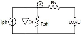
Fig.1: PV Cell circuit model
The behavior of PV cells can be described by five parameters (Iph, N, IS, RS, RSH) represents a physical PV cell/module. These five variables of PV cell/module are, in fact, related to two environmental criterions of solar insolation & temperature and owing to non-linear nature of equation.
3. SOLAR CELL: A DIODE PERSPECTIVE
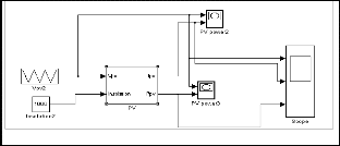
Solar cells are photo diodes on a large-scale and have same basic characteristics of a pn junction diode. The non-linarite in PV Cell V-I characteristics exist fundamentally due to the presence of in the circuit model of Fig. 1[1]. It is logical to begin with four quadrant study of diode characteristics under the dark and illuminated conditions. The circuit simulator MATLAB is used as an effective tool to convey the examination and the schematic used for this objective is shown in Fig. 2.
I I
I exp

q.V IRs
V IR
1 s
ph s
N.K .T
Rsh
IJSER © 2011 http://www.ijser.org
International Journal of Scientific & Engineering Research Volume 2, Issue 10, Oct-2011 2
ISSN 2229-5518
3.1. Diode Characteristics in dark Light
The schematic of Fig. 2 is simulated for obtaining PV Cell characteristics under the Dark and simulation results are shown in Fig. 3. In Dark light, the photon generated current is zero. Obviously, the PV cell in Dark is a passive device and acts like a standard diode.
Fig 3: PV Cell Characteristics in Dark
The V-I characteristic curves of PV cell are similar to a diode under forward and reverse bias conditions respectively. The noteworthy point here is that the device diode behaves with forward current and voltage in 1st-quadrant and with reverse current and voltage in 3rd–quadrant.
3.2. PV Cell under Illumination
The effect of Illumination on a PN junction can be studied by increasing the value of source current Idc in Fig.1 from its zero value (for dark), to a value of four amps, taken to be an equivalence of 100% radiation. As the photon current, Iph is directly proportional to the incident insolation, a value of 3Amps will represent 75% or 0.75 sun, a value of two amps will correspond to 50% and likewise. The family of characteristic curves of Fig 4 can be produced for varying insolation level.
Fig 4: PV Cell characteristics under illum ination
3.3. V-I CHARACTERISTICS OF PV CELL
The effect of solar insolation is actually to shift diode characteristic curve downward along the current axis; making it to operate in IVth-quadrant as shown in Fig.4. The shifting of the diode characteristic curve with increasing insolation along the current axis reveals that current is proportional to incident sunlight while voltage
IJSER © 2011 http://www.ijser.org
capability of the cell is almost constant from very low light levels. This behavior indeed enunciates that a PV- cell behaves more like a current source than a voltage source, and also PV-effect occurs in fourth quadrant only. Here, it is noteworthy for the cell to generate both current and voltage and acts as a photovoltaic generator. Thus, the fourth quadrant portion of the diode characteristic curve is called V-I curve of PV cell in solar photovoltaic terminology. To produce a solar cell V-I curve; the fourth quadrant of the characteristic's curve is flipped vertically about the voltage axis into the 1st quadrant as shown in Fig.5. This is done so that the current direction is positive rather than negative. This is strictly in accordance with the convention that a generator must source positive current from its positive terminal.
Fig 5: PV Cell Characteristics
4. SHUNT CONTROLLERS FOR VOLTAGE DIP MITIGATION
Shunt devices are normally used to neutralize minute voltage deviations which can be regulated by reactive power insertion. The capability to control the fundamental voltage at a particular point relies on the grid ohmic resistance and the power factor of the load. The compensation of a voltage dip by current injection is hard to attain since the grid impedance is usually low, and the introduced current has to be very high to increase the load voltage. The shunt controller can be current or voltage controlled. When the converter is a current controlled, it can be represented as a grid-feeding component that supports the grid voltage by modifying its reactive output power matching to the grid voltage diversities. When the converter is a voltage can be represented as a grid-supporting part that controls its output voltage. However, also in this second case, the control action results in injecting the reactive power in order to regularize the voltage. The vector diagrams of a shunt controller formed to provide only reactive power are stated in Fig. 6. When the grid voltage is 1p.u., the converter supplies the reactive power absorbed by the load, and the vector diagram of the current- or voltage- controlled converter is the same, then, in the first case, it is controlled by the compensating current I, and in the one, it is controlled by the load-voltage, as underlined in Fig. 6(a) and (b).
International Journal of Scientific & Engineering Research Volume 2, Issue 10, Oct-2011 3
ISSN 2229-5518


Fig 7: Phasor diagram of the shunt controller providing both active and reactive powers. (a)Norm al conditions. (b)Phasor diagram for compensation of a voltage dip of 0.15pu
Hence, during voltage sag, the amount of reactive current needed to maintain the load voltage at the desired value is inversely proportional to ωLg. This means that a large inductance will help in mitigating voltage sags, although it is not desirable during normal operation.
Fig 6: Vector diagram of the shunt controller providing only reactive power. (a) Current-controlled converter in normal conditions. (b) Volt age-controlled converter in normal condition. (c) Vector diagram for compensation of a voltage dip of 0.15 pu.
When a voltage sag occurs, the converter provides reactive power in order to support the load voltage, and the grid current Ig has a dominant reactive component, i.e.,
Ig + Ic = Iload
The amplitude of the grid current depends on the value of the grid impedance since


Where VLg is the inductive voltage drop shown in Fig.
6(c). If the shunt controller supplies the load with all the
required active and reactive powers, as in normal
conditions, it provides a compensating current Ic= ILoad ;
hence, the system operates as in island mode, and Ig =0 .
In case of a voltage dip, the converter has to provide the active power required by the load, and it has to inject the reactive power needed to stabilize the load voltage, as shown in Fig. 7(b). The grid current in this case is reactive. It can be seen that
5. PV SYSTEM WITH SHUNT-CONNECTED MULTIFUNCTION CONVERTER
In case of low-power applications, it can be beneficial to use the converter that is parallel linked to the grid for the amends of minute voltage sags. This feature can be viewed as an ancillary service that the system can furnish to its sectional burdens. The suggested PV converter functions by providing active and reactive powers while the sun is present. At low beam of light, the PV converter only acts as a harmonic and reactive power compensator. I is difficult to improve the voltage quality accompanied by a shunt controller since, it cannot grant simultaneous control of the output voltage and current. In addition, a large-rated converter is necessary in order to compensate voltage sags. However, this topology is acceptable in PV applications since the PV shunt converter must be rated for the peak power produced by the panels. In the proposed system, the PV converter operates as a shunt controller; it is connected to the load through an LC filter and to the grid through an extra inductance L*g of 0.1 pu, as shown in Fig. 8.
IJSER © 2011 http://www.ijser.org
International Journal of Scientific & Engineering Research Volume 2, Issue 10, Oct-2011 4
ISSN 2229-5518
in this case, the third and fifth ones are compensated (Fig.
9).
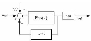
Fig.9. Proposed repetitive-based controller, Control schem e.
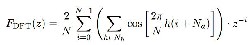
The nominated repetitive controller is located on a finite impulse response (FIR) digital filter [20]. It is a “moving” or “running” filter, accompanied by a window identical to one fundamental period, defined as,
Fig 8: Grid-connected PV system with shunt controller functionality.
Usually, in case of low-power applications, the systems are connected to low-voltage distribution lines whose impedance is resistive. Yet, in the suggested topology, the grid can be considered mainly inductive as a consequence of L * total on the grid side. Though, the voltage regulation is clearly affected by the voltage drop on the inductance L *, it is not comfortable picking an inductance Lg* of high value in order to bound the voltage drop in grid normal conditions. It denotes the main disadvantage of the proposed topology.
5.1. CONTROL OF CONVERTER
The recommended converter is the voltage regulated with a repetitive algorithm. An MPPT algorithm changes the phase displacement among the grid voltage and the ac voltage provoked by the converter to inject the utmost power in the given atmospherical conditions. Hence, current injection is indirectly controlled. The magnitude of the current hinges on the difference between the grid voltage and the voltage on the ac capacitor Vc . The phase displacement between these two voltages determines the injected active power (decided by the MPPT algorithm), and the voltage amplitude difference determines the reactive power exchange with the grid. The injected reactive power is limited by the fact that a voltage dip higher than 15% will force the PV system to disconnect (as requested by standards). The active power is limited by the PV system rating and leads to a limit on the maximum displacement angle dδmppt. Moreover, the inverter has its inner proportional integral (PI)-based current control loop and over current protections.
A phase-locked loop (PLL) discovers the amplitude Vpeak and phase δgrid of the grid voltage. Afterwards, the phase displacement dδmppt is furnished by the MPPT algorithm depicted in Section 5.2. The voltage error between Vref and Vc| is preprocessed by the repetitive controller, which is the periodic signal generator of the fundamental component and of the selected harmonics:
IJSER © 2011 http://www.ijser.org
where N is the number of samples within one fundamental period, Nh is the set of selected harmonic frequencies, and Na is the number of leading steps determined to exactly track the reference.
The repetitive controller guarantees a exact tracing of
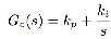
the chosen harmonics, and it provides the testimonial for the internal loop. In it, a PI controller enhances the steadiness of the system, contributing a low-pass filter function. The PI controller Gc,
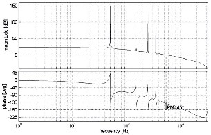
is designed to ensure that the low-frequency poles have a damping factor of 0.707. The open-loop Bode diagram of the system is shown in Fig.10: stability is guaranteed since the phase margin is about 45◦.
Fig.10 .Proposed repetitive-based controller, Open-Loop Bode diagram of the system obtained using kFIR=1, Na =0, and Nh = {1;3;5}.
In normal operational mode, the shunt-connected converter injects the surplus of active power in the utility grid, as well as c the harmonics of the load voltage. At low beam of light, the PV inverter only acts as a shunt controller, eliminating the harmonics. Controlling the voltage, Vc| , the PV converter is enhanced with the function of voltage dip compensation. In the presence of a
International Journal of Scientific & Engineering Research Volume 2, Issue 10, Oct-2011 5
ISSN 2229-5518
voltage dip, the grid current Ig is forced by the controller to have a sinusoidal waveform that is phase shifted by 900 with respect to the corresponding grid voltage.
5.2. MPPT ALGORITHM
The power provided from a PV array usually relies on the current atmospheric conditions (irradiation and temperature); therefore, in order to collect the maximum available power, the operating point requires to continuously be tracked using an MPPT algorithm [28]. To find the maximum power point (MPP) for all conditions, an MPPT control method based on the incremental conductance method [32], [34], which can tell on which side of the PV characteristic the current operating point is, has been used. The MPPT algorithm modifies the phase displacement between the grid voltage and the converter voltage, providing the voltage reference Vref . Furthermore, there is an extra feature
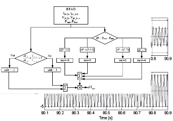
Fig.11. Flow chart of the modified MPPT
algorithm.
added to this algorithm that monitors the maximum and
minimum values of power oscillations on the PV side. In case of single-phase systems, the instant power oscillates with twice the line frequency. This oscillation in power on the grid side leads to a 100-Hz ripple in voltage and power on the PV side.
If the system operates in the area around the MPP, the ripple of the power on the PV side is minimized [33]. This feature can be used to detect in which part of the power– voltage characteristics the system operates. It happens in the proposed control scheme where information about the power oscillation can be used to find out how close the current operating point is to the MPP, thereby slowing down the increment of the reference, in order not to cross the MPP.
A flowchart of the MPPT algorithm is shown in Fig.
11, explaining how the angle of the reference voltage is modified in order to keep the operating point as close to MPP as possible. The MPP can be tracked by comparing the instantaneous conductance Ipv_k/Vpv _k to the incremental conductance dIpv/dVpv, as shown in the flowchart. Considering the power–voltage characteristic of a PV array, it can be observed that, operating in the area on the left side of the MPP, dδmppt has to decrease. This decrement is indicated in Fig. 11 with side = +1. Moreover, operating in the area on the right side of theMPP, dδmppt has to increase, and it is indicated with side =+1. The increment size determines how fast the MPP is tracked. The measure of the power oscillations on the PV side is used to quantify the increment that is denoted with incr in Fig. 11.
IJSER © 2011 http://www.ijser.org
6. SIMULATION RESULTS
The PV system with power quality conditioner functionality has been tested in the simulation with the following system parameters: the LC filter made by 1.4- mH inductance, 2.2-µF capacitance, and 1-Ω damping resistance; an inductance L * of 0.1 pu; and a 1-kW load.
The control has been validated in the presence of
sudden changes of the PV power caused, for example, by
irradiation variations. The reported tests show the
behavior of the MPPT for a voltage sag. The results refer to the case of a controlled inverter in order to collect the maximum available power (i.e.,2 kW).
The controller parameters are kFIR = 0.3, N = 128 (sampling frequency = 6400 Hz), Na = 0, kp = 4.5, and ki =
48. The set of test aims to demonstrate the behavior of the
system during a voltage sag and the interaction of the voltage control algorithm with the MPPT algorithm.
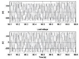
Fig 12: Performance of the volt age-controlled shunt converter with
MPPT algorithm: grid voltage E and load voltage Vload.
International Journal of Scientific & Engineering Research Volume 2, Issue 10, Oct-2011 6
ISSN 2229-5518
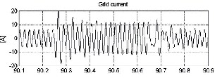
Fig.13. Performance of the voltage-controlled shunt converter with MPPT algorithm : grid current I , converter current I |, and load current Iload.
The simulation results, shown in Figs. 12 and 13, are obtained for a voltage dip of 0.15 pu. During the sag, the inverter sustains the voltage for the local load (Fig. 8), injecting a mainly reactive current into the grid. The amplitude of the grid current Ig grows from 4.5 to 8.5 A, as shown in Fig. 13, which corresponds to the reactive power injection represented in Fig. 14.
The inductance L|g connected in series with the grid impedance limits the current flowing through the grid during the sag. When the voltage sag of 0.15 pu occurs, the converter current grows from 8 to 10.5 A. For this reason, the shunt controller is not a good choice to compensate for deeper dips. Fig. 15 demonstrates the robustness of the presented MPPT algorithm to the voltage dip. In fact, with it are shown the voltage and current on the PV side during the sag. They are not significantly influenced by the dip.
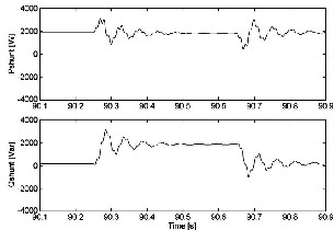
Fig 14: Active and reactive power provided by the shunt-connected m ulti-functional convert er to compensate the voltage sag of 0.15pu.
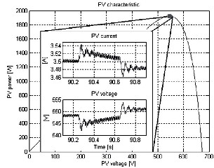
Fig.15. Power–voltage characteristic of the PV array and current and voltage on the PV side in the presence of a grid voltage sag of
0.85pu.
7. CONCLUSIONS
In this paper, a single-phase PV system with shunt controller has been presented. The PV converter is voltage controlled with a repetitive algorithm. An MPPT algorithm has specifically been designed for the proposed voltage-controlled converter. It is based on the incremental conductance method, and it has been modified to change the phase displacement between the grid voltage and the converter voltage, thus maximizing the power extraction from the PV panels. The designed PV system provides grid voltage support at fundamental frequency and compensation of harmonic distortion at the point of common coupling. An inductance is added on the grid side in order to make the grid mainly inductive (it may represent the main drawback of the proposed system). Experimental results confirm the validity of the proposed solution in case of voltage dips and nonlinear loads.
8. REFERENCES
[1] Dzung D. Nguyen, and Brad Lehman, “Modeling and Simulation of PV arrays under changing Illumination conditions,” IEEE COMPEL Workshop Troy, NY,USA, July 16-19, 2006, pp. 295-299.
[2] A. Zekry and A. Al-Mazroo, “A Distributed SPICE
Model of a Solar Cell,” IEEE Transactions on Electron
Devices, Vol. 43, No. 5, May 1996, pp. 691-700.
[3] David L. King, James K. Dudley, and William E. Boyson, “A Simulation Program for Phototvoltaic Cells, Modules,and Arrays,” 25th IEEE PVSC Conf. , Washington. DC, May 13-17, 1996, pp 691-696.
[4] J.A. Gow, and C.D. Manning, “Development of a photovoltaic array model for use in power electronic simulation studies,” IEE Proceeding Electric power Application, vol. 146, No. 2, March 1999, pp. 193-200.
[5] IEEE Standard for Interconnecting Distributed
Resources With Electric Power Systems, IEEE Std. 1547-
2003, 2003.
[6] IEEE Guide for Monitoring, Information Exchange,
and Control of Distributed Resources Interconnected
With Electric Power Systems, IEEE Std. 1547.3-2007, 2007.
[7] J. M. Guerrero, J. Matas, L. García de Vicuña, M.
Castilla, and J. Miret, Wireless-control strategy for parallel operation of distributed-generation inverters,” IEEE Trans. Ind. Electron., vol. 53, no. 5, pp. 1461–1470, Oct. 2006.
[8] J. M. Guerrero, J. Matas, L. García de Vicuña, M. Castilla, and J. Miret, “Decentralized control for parallel operation of distributed generation inverters using resistive output impedance,” IEEE Trans. Ind. Electron., vol. 54, no. 2, pp. 994–1004, Apr. 2007.
[9] K. De Brabandere, B. Bolsens, J. Van den Keybus,
A. Woyte, J. Driesen, and R. Belmans, “A voltage and frequency droop control method for parallel inverters,” IEEE Trans. Power Electron., vol. 22, no. 4, pp. 1107–1115, Jul. 2007.
IJSER © 2011 http://www.ijser.org
International Journal of Scientific & Engineering Research Volume 2, Issue 10, Oct-2011 7
ISSN 2229-5518
[10] M. Bollen, Understanding Power Quality Problems: Voltage Sags and Interruptions. Piscataway, NJ: IEEE Press, 1999.
[11] M. H. J. Bollen and I. Gu, Signal Processing of
Power Quality Disturbances. New York: Wiley, 2006.
[12] H. Kömürgügil and Ö. Kükrer, “A new control
strategy for single-phase shunt active power filters using
a Lyapunov function,” IEEE Trans. Ind. Electron., vol. 53,
no. 1, pp. 305–312, Feb. 2006.
[13] M. E. Ortúzar, R. E. Carmi, J. W. Dixon, and L. Morán, “Voltagesource active power filter based on multilevel converter and ultracapacitor DC link,” IEEE Trans. Ind. Electron., vol. 53, no. 2, pp. 477–485, Apr.
2006.
[14] B.-R. Lin and C.-H. Huang, “Implementation of a three-phase capacitorclamped active power filter under unbalanced condition,” IEEE Trans. Ind. Electron., vol.
53, no. 5, pp. 1621–1630, Oct. 2006.
[15] I. Exteberria-Otadui, A. López de Heredia, H.
Gaztañaga, S. Bacha, and M. R. Reyero, “A single synchronous frame hybrid (SSFH) multifrequency controller for power active filters,” IEEE Trans. Ind. Electron., vol. 53, no. 5, pp. 1640–1648, Oct. 2006.
[16] G. Escobar, P. Mattavelli, A. M. Stakovis, A. A. Valdez, and J. Leyva-Ramos, “An adaptive control for
UPS to compensate unbalance and harmonic distortion using a combined capacitor/load current sensing,” IEEE Trans. Ind. Electron., vol. 54, no. 2, pp. 839–847, Apr.
2007.
[17] D. O. Abdeslam, P. Wira, J. Mercklé, D. Flieller,
and Y.-A. Chapuis, “A unified artificial neural network architecture for active power filters,” IEEE Trans. Ind. Electron., vol. 54, no. 1, pp. 61–76, Feb. 2007.
[18] M. Routimo, M. Salo, and H. Tuusa, “Current sensorless control of a voltage-source active power filter,” in Proc. 20th IEEE Annu. APEC, Mar. 6–10, 2005, vol. 3, pp. 1696–1702.
[19] P. Wang, N. Jenkins, and M. H. J. Bollen,
“Experimental investigation of voltage sag mitigation by
an advanced static VAr compensator,” IEEE Trans. Power
Del., vol. 13, no. 4, pp. 1461–1467, Oct. 1998.
[20] P. Mattavelli and F. Pinhabel Marafao,
“Repetitive-based control for selective harmonic
compensation in active power filter,” IEEE Trans. Ind.
Electron., vol. 51, no. 5, pp. 1018–1024, Oct. 2004.
[21] F. Botterón and H. Pinehiro, “A three-phase UPS
that complies with the standard IEC 62040-3,” IEEE Trans. Ind. Electron., vol. 54, no. 4, pp. 2120–2136, Aug.
2007.
[22] G. Escobar, A. A. Valdez, J. Leyva-Ramos, and P.
Mattavelli, “Repetitivebased controller for a UPS inverter
to compensate unbalance and harmonic distortion,” IEEE Trans. Ind. Electron., vol. 54, no. 1, pp. 504–510, Feb. 2007. [23] G. Escobar, P. R. Martínez, and J. Leyva-Ramos, “Analog circuits to implement repetitive controllers UIT feedforward for harmonic compensation,” IEEE Trans.
Ind. Electron., vol. 54, no. 1, pp. 567–573, Feb. 2007.
[24] G. Escobar, P. R. Martínez, J. Leyva-Ramos, and P.
Mattavelli, “A negative feedback repetitive control
scheme for harmonic compensation,” IEEE Trans. Ind. Electron., vol. 53, no. 4, pp. 1383–1386, Aug. 2006.
[25] R. Griñó, R. Cardoner, R. Costa-Castelló, and E. Fossas, “Digital repetitive control of a three-phase four- wire shunt active filter,” IEEE Trans. Ind. Electron., vol.
54, no. 3, pp. 1495–1503, Jun. 2007.
[26] R. A. Mastromauro, M. Liserre, and A.
Dell’Aquila, “Study of the effects of inductor nonlinear
behaviour on the performance of current controllers for
single-phase PV grid converters,” IEEE Trans. Ind. Electron., vol. 55, no. 5, pp. 2043–2052, May 2008.
[27] R. A. Mastromauro, M. Liserre, A. Dell’Aquila, and R. Teodorescu, “Performance comparison of current
controllers with harmonic compensation for single-phase grid converter,” in Proc. 10th Int. Conf. Optimization Elect. Electron. Equip. OPTIM, Brasov, Romania, May 18–
19, 2006.
[28] W. Xiao, J. Lind, W. Dunford, and A. Capel,
“Real-time identification of optimal operating points in
photovoltaic power systems,” IEEE Trans. Ind. Electron., vol. 53, no. 4, pp. 1017–1026, Aug. 2006.
[29] H. Patel and V. Agarwal, “Maximum power point tracking scheme for PV systems operating under partially shaded conditions,” IEEE Trans. Ind. Electron., vol. 55, no. 4, pp. 1689–1698, Apr. 2008.
[30] I. Kim, M. Kim, and M. Youn, “New maximum power point tracker using sliding-mode observer for estimation of solar array current in the gridconnected photovoltaic system,” IEEE Trans. Ind. Electron., vol. 53, no. 4, pp. 1027–1035, Aug. 2006.
[31] W. Xiao, N. Ozog, and W. G. Dunford, “Topology study of photovoltaic interface for maximum power point tracking,” IEEE Trans. Ind. Electron., vol. 54, no. 3, pp.
1696–1704, Jun. 2007.
[32] J. Park, J. Ahn, B. Cho, and G. Yu, “Dual-module-
based maximum power point tracking control of photovoltaic systems,” IEEE Trans. Ind. Electron., vol. 53, no. 4, pp. 1036–1047, Aug. 2006.
[33] H. Hinz and P. Mutschler, “Voltage source inverters for grid connected photovoltaic systems,” in
Proc. 2nd World Conf. Exhib. Photovolt. Solar Energy
Convers., Wien, Austria, Jul. 1998, pp. 2045–2048.
[34] T. Esram and P. L. Chapman, “Comparison of
photovoltaic array maximum power point tracking
techniques,” IEEE Trans. Energy Convers., vol. 22, no. 2,
pp. 439–449, Jun. 2007.
[35] F. Liu, S. Duan, F. Liu, B. Liu, and Y. Kang, “A variable step size INC MPPT method for PV systems,” IEEE Trans. Ind. Electron., vol. 55, no. 7, pp. 2622–2628, Jul. 2008.
9. BIOGRAPHIES
A.Hari Prasad is currently pursuing master of technology program in Power Electronics and Electrical Drives in Mother Teresa Institute of Science and Technology affiliated to Jawaharlal Nehru Technological University, Hyderabad, Andhra Pradesh, India.
E-mail: hariprasad_ambati@yahoo.com
Mr.Y.Rajasekhar Reddy is working as asst.professor in Mother Teresa
Institute of Science and Technology, SanketkaNagar,Sattupalli, Khammam,A.P.-507303
Dr. P.V. Kishore is working as Professor at Mother Teresa Institute of
IJSER © 2011 http://www.ijser.org
International Joumal of Scientific & Engineering Research Volume 2, Issue 10, Oct-2011 8
ISSN 2229-5518
Sc1ence and Techmlogy, SanketkaNagar,Sattupalll, Khammam,A. P.-
507303
IJSER© 2011
http://www.ijser org