The research paper published by IJSER journal is about Photoelastic Stress Analysis & Finite Element Analysis of an Internal Combustion Engine Piston 1
ISSN 2229-5518
Photoelastic Stress Analysis & Finite Element Analysis of an Internal Combustion Engine Piston
Prof. H. V. Shete, Prof. R. A. Pasale, Prof. E. N. Eitawade
Abstract - Two dimensional photoelastic technique & Finite element analysis is used to analyse stresses in a piston of an Internal combustion engine. The stresses due to combustion gas load only are considered. The results from both the methods are compared and validated. Based on the results, modifications in the piston profile can be suggested ,so as to reduce the weight and hence to increase the power output of engine..
Index Terms- Fringe Pattern, Mesh, Nodes, Piston, Photoelastic material, Polariscope, Stresses.
1 INTRODUCTION
In recent years, more and more efforts are made to increase horse power to weight ratio of internal combustion engines. In order to
achieve the increased power to weight ratio, the necessity of design optimization of various internal combustion engine components is felt very seriously.
Lighter piston reduces the dynamic balancing problem to
a greater extent. So it is necessary to optimize the design of the piston to keep its weight minimum. This necessitates complete stress analysis of the piston. Analysis will help to modify the existing design for reducing the weight. This could be achieved by removing material from low stressed area and also by changing the contours, so as to keep the stresses within allowable limit.
Conventional strength formulae are not useful for analyzing the stresses in pistons. Photoelasticity and Finite Element Analysis is the best method for analyzing the stresses in pistons.

 Prof. H. V. Shete is currently working as Associate Professor in Mechanical Engineering in Ashokrao Mane Group of Institutions, India- 416112, PH – 09823925440. E-mail: sheteaditya@yahoo.co.in
 Prof. R. A. Pasale is currently working as Assistant Professor in
Mechanical Engineering in Ashokrao Mane Group of Institutions, India- 416112, PH – 09158432298. E-mail: rhlpasale@gmail.com
 Prof. E. N. Eitwade is currently working as Associate Professor in Mechanical Engineering in Tatyasaheb Kore Institute of Engineerring & Technology, India- 416113, PH – 09922848887. E- mail: enaait@yahoo.co.in
The loading on the piston can be broadly classified into two different categories. First is the mechanical load due to
combustion gas pressure and the second is the thermal load due to thermal gradient. The present problem deals with only the stresses produced due to combustion gas load in the portion above the gudgeon pin of an Internal combustion engine piston made of aluminum . Two Dimensional Photoelastic technique is used for the stress analysis. Two dimensional technique is used, as it is simple as compared to three dimensional technique and also gives quick results[1]. A loading frame is designed to simulate uniform gas load along the top boundary of the model and the resulting isochromatics are studied. The same piston is considered for Finite Element Analysis. The results of both techniques are compared and are agreed to each other. Modifications in the piston profile can be suggested to reduce the weight of the piston without exceeding the maximum allowable stress limits.
2 PISTON UNDER CONSIDERATION
The piston of water cooled oil engine is selected for present case
with following specification-
Engine Specifications:
Make - Kirloskar oil engine ltd.
Type - Vertical, Compression ignition, Four stroke cycle. Water cooled diesel engine
Combustion - Open or direct type combustion chamber in an aluminum alloy piston.
Specific fuel consumption - 185 g / bhp at full load. Speed - 1500 rpm.
No. of cylinders - 1
Bore - 160mm Stroke - 240 mm Compression ratio - 17.5: 1
KW (hp) - 5.2 (7)
Cylinder capacity - 0.6615 liter
IJSER © 2012 http://www.ijser.org
The research paper published by IJSER journal is about Photoelastic Stress Analysis & Finite Element Analysis of an Internal Combustion Engine Piston 2
ISSN 2229-5518
Torque at lull load - 0.033 KN-m
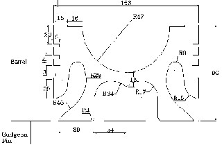
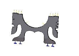
Thus, two dimensional piston models selected for analysis by photoelastic method and finite element method is shown in fig. 1.
All Dimensions are in mm
Fig. 1. Two dimensional piston model under investigation
3 MODEL PREPARATION
Photoelastic sheets required for the two dimensional models of
piston under consideration are prepared, by casting liquid photoelastic material into acrylic moulds. A homogenous mixture of Araldite Resin CY 230 and hardener HY 951 is used as liquid photoelastic material. Both the Araldite resin and hardener are manufactured in India by CIDATUL Ltd.
Proportion of Araldite resin to hardener is 100:10 by volume. For the present problem, thickness of sheet to be prepared is selected as 6 mm. Models of the piston is cut from this sheet. The homogeneous mixture of resin and hardener is poured in the moulds without producing air bubbles. The temperature of surrounding during sheet preparation should be in between 25° C to 35° C, to avoid moisture entrapment in sheet. After the setting time of 24 hours, the sheet is removed from the mould and then it is hardened completely by keeping on plain platform for five days. This sheet is examined in polariscope for locked in stresses and ensured free of them.
An aluminium template is used for making the models. The
models are rough-cut on fret saw and then accurately finished on a high speed dresser. Maximum possible efforts are made to stick to the dimensional tolerances, specified in the drawing. The model prepared is of the same size as that of the original piston.
4 CALIBRATION OF PHOTOELASTIC MATERIAL Material fringe value is an indication of the response of photoelastic material to load or stresses. As a check for this standard range of the material fringe value should lie between 3 kg/cm to 12 kg/cm. So calibration of the photoelastic material is necessary to get correct results.
The photoelastic material is calibrated by making a circular
disc out of the same sheet. The disc is loaded in increments under the diametral compression on polariscope to find the material fringe value. The fringe order at the centre of disc and corresponding load are recorded. The photoelastic material of the piston model is found to have a stress fringe value equal to 10.594 kg/cm, as shown in Table 1.
TABLE 1


STRESS FRINGE VALUE OF PHOTOELASTIC MATERIAL
Sr.No. | Actual load on the specimen (P) Kg | Material fringe value (f ) Kg/cm | Average fringe value (f ) Kg/cm |
1 | 17.5 | 11.016 | 10.594 |
2 | 25 | 10.014 | 10.594 |
3 | 42.5 | 10.752 | 10.594 |
5 EXPERIMENTATION
A special loading fixture is designed, so as to apply uniform gas
pressure along the top boundary of the photoelastic piston model [4]. Fig. 2(a) shows the fixture. A specially designed latex-rubber tube is used to apply the uniform gas pressure on the top boundary of the model. A channel is formed on the top of the model to accommodate the rubber tubing. The tube, when pressurized, quickly expands to fill the channel and then exerts the uniform pressure along the top boundary of the model. The tube is pressurized using compressed air. One end of the tube is connected to a pressure gauge.
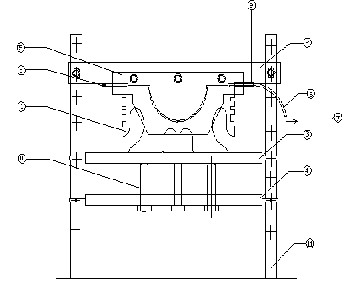
A rigid platform having ground finished top is used to support the model at its bottom. This simulates to the rigid support by gudgeon pin.
Fig.2(a). Loading Fixture
1. Photoelastic model of piston, 2.Upper Fixed Plate,
3.Movable Member, 4.Lower Fixed Plate, 5. Acrylic Plates,
6. Latex Tube 7.To Pump for pressurizing 8.Pressure Gauge
9. Cover for tube 10. Leveling Bolts 11. Polariscope Frame
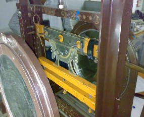
The arrangement of experimental set up on polariscope is shown in fig. 2(b). Polar coordinates are marked on the two dimensional photoelastic model of piston as in fig. 2. The angle between two successive points is kept 10° or less. The model is loaded in loading fixture on polariscope. The uniform pressure of
2 Kg/cm2 is applied on the model. Then by using Tardy’s method
of compensation, isochromatic and isoclinic reading are noted for
each of interest.
IJSER © 2012 http://www.ijser.org
The research paper published by IJSER journal is about Photoelastic Stress Analysis & Finite Element Analysis of an Internal Combustion Engine Piston 3
ISSN 2229-5518
TABLE 2(a)
STRSSES IN METAL PROTOTYPE OF PISTON

Fig. 2(b). Experimental set up on polariscope
From these readings fractional fringe order (Nf) is calculated for each point of interest and shown in table 2(a) and table 2(b). The stresses at each point of interest in photoelastic piston model are found by using equation (1) as-
 (1)
(1)
Where,
 = Stresses at point of interest in photoelastic piston model kg/cm2,
Nf = Fractional fringe order,
f = Material fringe value kg/cm,
h = Thickness of photoelastic piston model = 0.6 cm, The stresses in the metal prototype of the piston are
found out by the law of similarity or equation (2) -
 (2)
(2)
Where,

= ratio in scale = 1
= ratio in thickness = 1 (unit thickness)
= 30 Kg/cm2 (taken from manual corresponding to compression ratio)
 = 2 Kg/cm2
The resulting stresses are shown in table 2(a) and table 2(b).
TABLE 2(b)

STRSSES IN METAL PROTOTYPE OF PISTON
Points of Interest | Fractional Fringe Order (Nf) | Stresses in Metal Piston ( p) N/mm2 | Nature of Stresses |
1’ | 0.222 | 5.728 | compressive |
2’ | 0.252 | 6.504 | compressive |
3’ | 0.530 | 16.260 | compressive |
4’ | 1.277 | 32.958 | compressive |
5’ | 1.635 | 42.180 | compressive |
6’ | 1.858 | 47.953 | compressive |
7’ | 0.625 | 16.130 | compressive |
8’ | 0.116 | 02.993 | compressive |
9’ | 0.027 | 0.969 | compressive |
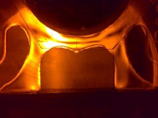
Fig.3. Isochromatic Fringe Pattern in Piston Model of
Photoelastic Material
6 EXPERIMENTAL RESULTS
IJSER © 2012 http://www.ijser.org
The research paper published by IJSER journal is about Photoelastic Stress Analysis & Finite Element Analysis of an Internal Combustion Engine Piston 4
ISSN 2229-5518
The stresses in metal prototype piston are shown in table 2(a) and table 2(b). The stresses are also marked on polar plot of stresses as shown in fig.4. To draw polar plot, stress value are represented as a distance from the inner piston surface along a line drawn through central reference point. Tensions are represented outside the datum surface and compression is represented inside.

Maximum Stress = 47.953 N/mm2 (compressive) Minimum Stress = 0.969 N/mm2 (compressive)
Fig.5. Model and Boundary
Conditions
8 FINITE ELEMENT ANALYSIS RESULTS
The stresses of each point of interest in piston are shown in table 3.
Scale: 1 cm = 2.5 N/mm2
Fig.4 Polar Plot of Stresses in the Piston
TABLE 3
STRESSES IN THE PISTON AT 2 Kg/cm2
7 FINITE ELEMENT ANALYSIS
5.1 MODEL DATA
Material Data:-
Material: Aluminum alloy (Duralium) Young's modulus: 6.75 x 10⁴ Mpa
Maximum Stress = 46.9 N/mm2
2
(compressive)
Poisons ratio: 0.34
Static Analysis:
Minimum stress = 0.09 N/mm
9 COMPARISON
(compressive)
Element data:
Three-nodded triangular element (OCTREE Tetrahedron) having single degree of freedom is used for meshing the model [12].
Mesh Data:
Nodes: 575
Elements: 1466
Boundary conditions
The external static force (Uniform pressure load) 2 Kg/cm2 and constraints are applied to the-model, as shown in Fig.5.
The results of two dimensional photoelastic method and finite
element method are compared with graphical representation
shown in fig. 6.
IJSER © 2012 http://www.ijser.org
The research paper published by IJSER journal is about Photoelastic Stress Analysis & Finite Element Analysis of an Internal Combustion Engine Piston 5
ISSN 2229-5518
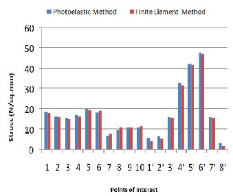
Fig. 6. Comparison of Photoelastic and FEM Results
[10] Manuel Valdes, Jesus Casanova and Antonio Ravira, “Design of carbon piston using transient heat transfer and stress analysis”, SAE Technical paper series.
[11] L.S.Srinath,M.R.Raghawan,K.Lingaiah, “Experimental
stress analysis”, Tata-McGraw hill publication,Delhi.
[12] Gudimetal P., Gopinath C.V., “ Finite element analysis of
reverse engineered internal combustion engine piston”, King Mongkut’s university of technology, North Bangkok Press, Bangkok, Thailand.
[13] S.P.Timoshenko,J.N.Goodier, “ Theory of elasticity”, m
McGraw hill international.
10 | 1. | CONCLUSIONS Stress is compressive at all the boundaries except at the back of crown, where stresses are tensile. |
| 2. | The tensile stresses are smaller than compressive stresses. |
| 3. | Lower stresses are observed at the outer surface of gudgeon pin boss and at the top surface of the crown. |
| 4. | Considering above stress pattern modified piston can be made by removing material from low stressed areas of |
| | the original piston. |
REFERENCES
[1] M.D.Rohrle, “Determination of stresses and deformation on piston by means of computer programmes and
photoelasticity” A.S.M.E. publication.
[2] M.D.Rohrle, “Investigation of stresses and deformation in
piston with the help of computer programming and
photoelasticity”. Department of MAHLE.
[3] V.L.Maleev, “Internal commotion engines”, McGraw-hill
International Company.
[4] Peter Ingham,David Fletcher Jones, “Photoelasticity applied to piston design”,Wellworty Topics, Spinge ,1972.
[5] M. Mihara, T.Kokubu, and K.Hirata, “A Photoelasticity study and calculation of Steady and cyclic thermal stresses of diesel engine piston”, Nagasaki technical institute and Mitsubishi heavy industries Ltd. Japan.
[6] J.W.Dally and W.F.Riley,“ Experimental stress analysis”,
McGraw-hill publication.
[7] Dr.Ing.Manfrerd Rorhle, “Piston for high output diesel engine”, Indian railway’s meeting , Bombay,1973.
[8] A.J.Durelli, R.K.Lake, “Device for applying uniform loading to boundaries of complicated shape”, Armour Reaserch Foundation,Chicago.
[9] C.S.Desai , J.F.Abel, and J.N.Reddy, “Introduction to the
F.E.M.”,G.B.S.Publication,Dehli.
IJSER © 2012 http://www.ijser.org