Fig.1. Schematic diagram of receiver operation of display unit.
Fig. 2. Receive time chart of the receiver operation of dis- play unit.
International Journal of Scientific & Engineering Research Volume 2, Issue 4, April-2011 1
ISSN 2229-5518
Peripheral Interface Controller based the
Display Unit of Remote Display System
May Thwe Oo
Abstract— This paper expresses about how to construct the peripheral interface controller (PIC) based the display unit of the remote display system. The remote display system can be used to display the token number that is to know the people. It is also intended for use in clinic, hospitals, bank, and etc. In this research, the peripheral interface controller based remote display system is used for displaying the number and the character. The remote display system consists of two portions: display unit and console unit. The display unit of remote display system contains the display controller, three seven-segment Light Emitting Diode (LEDs), Diode matrix, Category display LEDs and DSUB9 connector. The display controller is controlled by the microcontroller PIC16F873. It controls to display the token numbers. And then it can control at the diode matrix to display the three kinds of character such as A, B, and C. The three numbers of seven-segment LEDs will display the token number from one to 999. The diode matrix helps to display the category display LEDs. The category display LEDs will display one kind of characters. In the research work, the category display LEDs can be displayed only three kinds of characters. For the display unit, the DSUB9 connector applies the data that is from the console unit of the remote display system. In this research work, the display unit works as the receiver the console unit works as the transmitter in remote display system. This paper explains about the design, construction, testing and result of a remote display system.
Index Terms— Diode Matrix, Display Unit, Light Emitting Diode, Peripheral Interface Controller, Remote Display System.
—————————— • ——————————
HIS display system is very useful in many applica- tions. To advertise, to express the number, the remote display system can be used. Because of the token number can be expressed by using the display system. The token number may be used in banks, financial insti- tutions, clinics and etc. The display unit of the remote display system can be controlled by the microcontroller PIC16F873. The token number is displayed by the large- sized seven- segment Light Emitting Diodes (LEDs). The category display LED can be expressed the three charac- ters. This research consists of two modules; one for the construction of hardware circuit (including interfacing circuit and LED matrix circuit) and other for how to con- trol the process by using peripheral interface controller (PIC). In this research, the hardware controlling program is Assembly programming language. The circuit compo- nents consist of resistors, transistors, Integrated Circuit (ICs), LEDs and other accessories. The remote display system consists of two parts. They are console unit and display unit. The display unit is used to display the num- bers. That number is needed to know the people. That numbers may be the token number for using many public places. For examples, the token number may be used in the banks and financial institutions, calling the patients one by one at the clinics, calling the candidates at the in- terviewing and etc. There are many ways to display the
number.
————————————————
An increasing number of banks are computerizing their operations. For actual field use, the display with target LED arrays must be replaced. No other hardware is needed, except the displays and the buffers. The absence of any seven segment decoder chip like 7447 is to be no- ticed. Because of all the decoding is done entirely by software. Time division multiplexing is another impor- tant concept. The four numbers of seven-segment dis- plays share a common data bus. The PC places the first digit on the data bus, and enables only the first seven- segment unit. After a delay of one millisecond, the digit is replaced by the next digit, but this time only the second display unit is enabled. After displaying all the four digits in this way, the first unit is enabling again. The cycle re- peats itself over and over. Another feature provided by the software is the ability to suppress leading zeros. Number five is displayed as 5, rather than as 0005. This is usually done by the hardware using the so called ‘ripple blanking’ facility of the decoder chips. Finally, the com- puter emits a musical sound whenever there is a change in the displayed number, to attract attention. A regulated
5-volt power supply is recommended [1].
Electronic bank token number display systems are quite popular with bank and financial institutions nowadays. These can be used by general practitioners in their clinics to call the patients one by one, and by interviewing com- mittees to call the candidates. In most applications, there
IJSER © 2011 http://www.ijser.org
International Journal of Scientific & Engineering Research Volume 2, Issue 4, April-2011 2
ISSN 2229-5518
are two sets of displays, a small one kept inside the cabin of the person controlling it, and a large one kept outside for visitors. There is a keyboard for teller to enter token numbers. The large size plasma devices and TTL chips are being used in the constructing of bank token display [2]. In digital bank token number display system, the dis- play device circuit is used to control both the common cathode LED and common anode plasma displays. A well regulated transistorized circuit provides power to TTL chips as well as to high voltage plasma displays.
The digit display part of the display unit is made to light up by 1 digit to suppress an electric current. The lighting-up time of one digit becomes 1/3 and the light falls. When little flow of the electric current occurs, the color patches occurs to the displaying. The display data is hold by the latch register (74LS 273). The 74LS273 which is D-type flip-flop (D-FF) as the latch register to hold the display of the LED is used. The eight D-FFs are housed in one piece of IC. One 74LS273 is used to control one seven- segment LED. It inputs the data to D terminal to make hold. First, the data for the 100th is outputted to RB6 from RB0 and it is inputted to all the latch registers. Next, RA0 is made H and only the CK of the latch register (IC five) for the 100th is made H level. By this, a 100th digit is dis- played in LED1.
The display unit of the remote display system is based on the PIC16F873. And it uses the asynchronous commu- nication of PIC16F873. In asynchronous communication, there are two operations: Transmitter operation, Receiver operation. Fig. 1 showed the schematic diagram of receiv- er operation of PIC16F873 in the display unit.
Fig.1. Schematic diagram of receiver operation of display unit.
Fig. 2. Receive time chart of the receiver operation of dis- play unit.
The following flowchart shows the outline of the software processing of the display unit of the remote display sys- tem.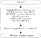
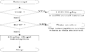
Fig. 3. Software flowchart for the display unit.
In the label definition, the frequently used commands are assigned. The data area is automatically assigned from 20h by CBLOCK directive. ENDC is used for the ending of assignment. The label ‘data-h’ is used for the area which stores 100th data. Similarly, the label ‘data-t’ is assigned for the area which stores 10th data, ‘data-u’ for the area which stores first data. And ‘cdisp-p’ is used for
IJSER © 2011 http://www.ijser.org
International Journal of Scientific & Engineering Research Volume 2, Issue 4, April-2011 3
ISSN 2229-5518
the area which stores a category display scan position.
‘ddisp-p’ is to store a seven-segment LED display scan
position. ‘rcv-p’ is the area which counts a received data.
And ‘r-category’ is the workarea to use for the change of the received category data. When making the power ON of the PIC, the instruction is executed from zero address of the program memory. When there is interruption processing, processing is began for the address4. And then it makes each processing jump with the GOTO in- struction. The initialization processing is done after turn- ing on. In this processing, all ports of the PORTA are set output mode. And all ports of PORTB are also set to out- put mode and are used for the segment control of the sev- en-segment LED. RC0, RC1, RC2, RC3 are set to output mode for the scan of the category display. RC7 pin of PIC16F873 is the only input mode and to receive the transferred data form the console unit.
For the USART, the most of the registers about the setting of a USART are in bank1. Therefore, it is necessary to be careful of the bank designation. The designation of the asynchronous serial communication with 9600bps trans- mission speed is done. This receiving interrupting occurs when the data is received in the receiving buffer. When the initialization of the USART ends, the receiving opera- tion is immediately done. When the initialization of inter- ruption will start, Global Interrupt Enable bit (GIE), Peri- pheral Interrupt Enable bit (PEIE), and Timer0 Overflow Interrupt Flag bit (T0IF) are set. To use the interruption of transmission complete, PEIE must to set.The initialization processing is ended. Then, it waits for the interruption only.
As the main processing, it repeats the execution of the
same address. In the interruption process subroutine, two
kinds of interruptions are used. They are interruption by
the time-out of TMR0 and the interruption when the data is received. The interruption of TMR0 is identified by the TOIF bit of the INTCON register and the data receive interruption is identified by the RCIF bit of the PIR1 regis- ter.. The RETFIE instruction is executed at end of the in- terruption processing. It becomes the interruption possi- ble condition.
The interruption occurs every two milliseconds with TMR0. The interruption flag of TOIF should be cleared first. If TOIF bit is not cleared, the interruption occurs without waiting the desired time. Therefore, the setting of the timer value of TMR0 is needed. As for the control of the category display, one row is done every time it inter- rupts in the two milliseconds. The specification of the row is done by the portC. As for the seven-segment LED con- trol, a three digit figure is displayed by the seven-segment LED. The one digit is controlled every two milliseconds about these LEDs. The digit specification of seven- segments is done by RA0, RA1, and RA2. And RA3, RA4, RA5 of the PIC16F873 is used for the category display
specification. For displaying the seven-segment LEDs, RA0, RA1, RA2 must be rewritten while d\saving this value.
The following flowchart shows the LED control
process.![]()
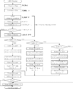
Fig. 4. Software flowchart for subroutine of LED control process.
Therefore, it makes data “0” except the category speci- fication by the AND. By suing the AND, the result be- comes “1” only when both data is “1”. If the bit that fixing value in the instruction is “1”, the contents don’t change. When the bit that is fixing value is “0” always becomes “0”. The digit specification data of the seven-segment LED is set to RA0-2. Now, the calculation of the OR is used. When either of the data is “1”, the result becomes “1”. If the contents of the bit that fixing value in the in- struction is “0”, the contents do not change. When the bit that is the fixing value is “1”, the contents always be- comes “1”. When the digit specification is ended, the segment data will be to display. The segment data to dis- play is written in the portB. It reads the content in the received data area of each of the digits and writes in the portB. It makes writing processing to the portB common and a processing step is reduced.
The following flowchart is the software flowchart for sub-
IJSER © 2011 http://www.ijser.org
International Journal of Scientific & Engineering Research Volume 2, Issue 4, April-2011 4
ISSN 2229-5518
routine of data receives process.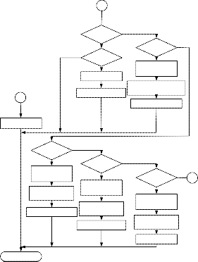
(a)
A
NO Start?
YES NO
Start data?
YES Read start data
Receive position +1
B
NO Category?
YES Translate to
display data
SET category data
PORTA= 00CCCXXX
Receive position +1
the received data is cleared. When the overrun occurs, it stops the receiver and it must be started once again. This process must be always done when the overrun occurs.
It clears all display data after that to find that the over- run occurred in the process. After the overrun error is checked, the frame error is checked. The frame is from the start bit to the stop bit. When a stop bit is not detected after detecting a start bit, the frame error occurs. If a nor- mal frame is received, the error passes away. When the frame error occurs, it clears display only. If the frame er- ror occurs, the Framing Error (FERR) bit of the Receive Status and Control Register (RCSTA) register is set. And then the category data, 100th data, 10th data and 1st data are cleared. The received position is almost cleared. The interrupt is ended.
After the frame error is checked, the start process is
checked. If the frame error does not occur, the start
process may be occurred. The category, 100th, 10th and 1st
data is sent sequentially from the console unit to the dis-
play unit. The information which shows the kind of the data isn’t included in each data. The kind of the data is decided in order to receive. The console unit sends start data first and transmits category, 100th, 10th, and 1st data continuously in the order. In the receiving process, it
Clear receive position
NO
100th ?
YES Translate to
display data
Write 100th data
DATA_H
NO
10th ?
YES Translate to
display data
Write 10th data
NO
1st ? C
YES Translate to
display data
it is read and the received position is set. Then, the re- ceived position is incremented and the interrupt is ended. When the data except the start data comes in the start data receiving position, the data is canceled and the in- crementation of the receiving position is not done.
The category data is received behind the start data. Af- ter the start data is checked, the category data will be checked. The category data which is sent from the console unit is sent in the form to use in the console unit. The bit
Receive position +1
End Interrupt
DATA_T
Receive position +1
(b)
Write 1st data
DATA_U Clear position
configuration and the bit contents of the data that is sent from the console unit to the display unit is different. In the received data, bit four-six is the data which shows a category. Bit six indicates “A”, bit five indicates “B”, and bit four indicates “C”. And, “0” indicates lighting-up and “1” indicates going-out.
If the category data is received, it is checked to be ‘A’
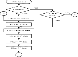
Fig. 5. Software flowchart for subroutine of data receive
process: (a) for checking the overrun rrror and frame er-
ror and (b) for checking the category and LED.
The data receive process makes the data receiving from the console unit. This process is started by the data re- ceive interruption by the Receive Interrupt Flag (RCIF) bit of the PIR1 register. It is different from the other interrup- tion display bit and to clear RCIF bit by the software is not necessary. It is cleared by the hardware in reading the data which was received to RCREG. When the data is received, the overrun error must be checked. If an over- run condition occurs, the Continuous Receive Enable (CREN) bit of Receive Status and Control Register (RCSTA) must be cleared. Then the CREN bit is set and
firstly. As for the display unit, bit three-five indicates a category. Bit three corresponds to “A”, bit four corres- ponds to “B” and bit five corresponds to “C”. In the dis- play unit, “0” indicates going-out and “1” indicates light- ing-up. The difference is due to the difference of the hardware of each unit. In the number data receive process, the 100th data, the 10th data and the 1st data are received in the order following the category data. The form of the console unit and the form of the display unit are different about these data. The bit position is the same and the meaning is opposite to “0” and “1”. In the console unit, ‘0’ is lighting-up and ‘1’ is going-out. In the display unit, “0” is going-out and “1” is lighting-up.
The Exclusion OR is used to reverse “0” and “1”. Ac- cording to Exclusive OR, “0” is output if being a value
IJSER © 2011 http://www.ijser.org
International Journal of Scientific & Engineering Research Volume 2, Issue 4, April-2011 5
ISSN 2229-5518
with the same data and “1” is output when the value is different. The result may reverses when calculating in Exclusion OR with “1”. When the received data is “01001111”, the result of execution of Exclusion OR with “11111111” is “10110000”. This is the value which re- versed “0” and “1” of the received data. A translated val- ue is written in the storage area which corresponds to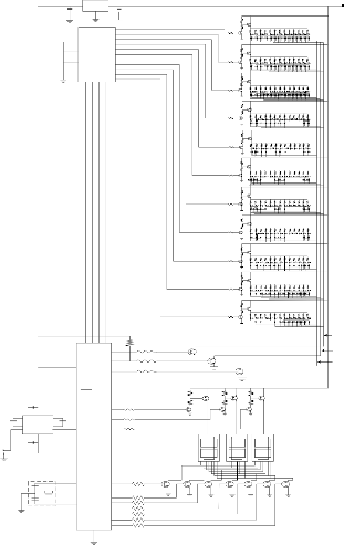
the PIC16F873. Fig. 6 shows the circuit diagram of the display unit of the remote display system.In the portion of design of display unit of the remote display system, the following circuits are including: the seven-segment LED control circuit, the category display control circuit, the RS232C control circuit, PIC oscillator circuit and power circuit.
each of the digits.
When the data receiving stops in the condition that the
C5
24
CC
IC4
78L05 C6
0 1
1 2
R12
R13
1
TR
TR1
R34 -R46
+12V
frame would be received, being normal. The receiving
18 G1
19
2 3 2
IC2 3 4 R
G2 74H C15 4 5 6
14
R15
TR3
R47 -R59
processing has the possibility to make a mistake in the
12 GND
6 7
7 8
8 9
9 10
R2
TR4
kind of data. When the 100th data is receiving, the com-
munication stopped. And then, when the start data from
the console unit is receiving, it receives the start data as
10th data and category data as 1st data. Because it becomes
A B C D 10 11
23 22 2 1 20
R16
R R17
3
TR6
R18
R19
4
TR8
R20
R21
TR5
TR7
TR9
R60 -R72
R73 -R83
R84 -R92
start data waiting condition when 1st data is received, the
100th data, 10th data, and 1st data are canceled. So, the
normal receiving is done.
R5
TR10
R22
R23
6
TR12
R24
R25
7
TR14
R26
R8
TR11
TR13
TR
R93 -R100
R101 -R109
The objective of the project is to design the display unit of the remote display system. The display unit is controlled by PIC16F873. The display unit is displayed the number and character that is transferred from the console unit of the remote display system. The display unit of the remote display system consists of three numbers of seven-
11 12 1 3 14
RC1 RC3
RC0 RC2 5
RA3
6
20 RA4
R160
R157
R158
TR23
TR24
R27
TR16
R28
R29
9
TR18
R30
R31
10
TR20
R32
R33
11
TR22
15
TR17
TR19
TR21
R110 -R119
R120 -R132
R133 -R146
R147 -R156
A B
C
segment LEDs, diode matrix, RS232C interface,
PIC16F873, and four-to-sixteen decoder. The RS232 inter-
face is used to connect between the display unit and the
C1
4 2 16 1
DD
1 MCLR
RA5 7
RA0 2
3
R161
R162
R159
R164
R165
TR27
R166
TR26
R167
TR29
TR25
R168
TR28
R169
TR31
TR30
console unit of the remote display system. PIC16F873 con- trols the three numbers of seven-segment LEDs and diode
C2 5 IC3 3 C3
ADM232AAN 18
8 9
6 15
RX C4
RA1
RX RA2 4
IC1
R163
matrix.
The remote display system consists two portions: Display
G ND
PIC1 6F873
9 OSC1 RB6 27
R170
a g a
g a g
Unit and Console Unit. This project is to design the dis- play unit of the remote display system. PIC16F873 is used
X1
4MHz
10 O SC2
RB5 26
RB4 25
RB3 24
RB2 23
RB1 22
21
R171
R172
R173
R174
R175
R176
TR32 TR33 TR34 TR35 TR36 TR37 TR38
to control both the display unit and the console unit of the
remote display system. PORTA of the PIC16F873 is used
for output mode to display the number and alphabet. All
of PORTB is to display the segments of the seven-segment
LEDs. A +5V is used to power of the PIC and +12V is
used to the seven-segment LEDs and diode matrix. The
diode matrix is used to display three kinds of characters such as A, B, and C.
The display unit of remote display system is controlled by the PIC16F873. There are LED selecting circuit and seg- ment selecting circuit to display the numbers with three numbers of seven-segment LEDs. And there are the row selecting circuit and LED selecting circuit to display the three kinds of characters such as A, B, and C. The RS232 interface is used as the connector between the display unit and the console unit. There is a clock circuit to drive
V SS RB0
Fig.6. Proposed circuit diagram of the display unit of the remote display system.
4.2.1 Seven-segment LED Control Circuit
In the display unit of the remote display system, there are three number of seven-segment LEDs. It is the I/O port number limitation with PIC and to make an electricity consumption little. Only the circuit which displays 100th data is drawn in the Figure 4.2. The circuit for 10th and
1st is similar too. TR27 and TR26 are the circuit which
selects a controlled LED. The drive voltage of the large-
sized LED to be using this time is 12V. The drive voltage for one LED is about 2V. As for one segment, five LEDs are connected in series. So, the drive voltage of one seg- ment becomes from 10V to 14V. The LED which was used this time is an anode common type and the anode termin-
IJSER © 2011 http://www.ijser.org
International Journal of Scientific & Engineering Research Volume 2, Issue 4, April-2011 6
ISSN 2229-5518
al which applies + voltage is common to all the segments. Because an LED selecting circuit is put in the side of the + voltage, PNP type is used for the control transistor. When using NPN-type transistor for this circuit, the emitter of the transistor is connected with the anode terminal of the LED. In the case, the electric current control for the base becomes difficult.
TR26
TR27
TR32
Fig. 7. Schematic diagram of 7-segment LED control cir- cuit.
The TR27 is used for the output of PIC. This is because the voltage which is applied to the I/O port of PIC is li- mited to +5V. When making TR26 ON, it makes the base voltage of TR26 less than +12V (About11V). The electric current flows through the base with this. When making TR26 OFF, it makes base voltage +12V. So, about +12V voltage is applied to the base of TR26. The base of TR26 can not be directly driven by PIC. When making RA0 of PIC 0V (0 conditions), TR27 becomes OFF. Therefore, the base electric current of TR26 does not flow and TR26 be- comes OFF too. That is, LED1 does not light up. When making RA0 of PIC +5V (1 condition), the base electric current flows through TR27 and TR27 becomes ON. When TR27 becomes ON, the electric current flows through the base of TR26 and TR26 becomes ON condi- tion. By this, +12V are applied on the anode of the LED and the LED becomes the condition about which it is possible to light up.
The segment selecting circuit drives a lit segment. A seg- ment selecting circuit is put between the LED and the grounding. So, the transistor for the control can be direct- ly driven by PIC. In the left figure, a circuit for the "a" segment is drawn. The other segment control circuit is similar too. When making RB6 of PIC 0V (0 conditions), TR32 becomes OFF. Therefore, the electric current does not flow through the "a" segment of the LED and the "a" segment does not light up. The base electric current flows through the base of TR32 when RB6 of PIC is +5V (1 con- dition). With this, the electric current flows through the "a" segment and the "a" segment lights up. In this re- search, the common cathode seven-segment LED is used. So, the LED selecting circuit used only one NPN transis- tor for each seven-segment LED. For the segment select- ing circuit, one PNP transistor and one NPN transistor
are used. At the LED selecting circuit, that transistor is directly controlled by the portA of PIC. If the port A of PIC is 0V (0 condition), the transistor will be off and the LED does not light-up. When the portA of PIC is 5V (1 condition), the base electric current flows through the transistor. And the electric current through the LED and the LED will be light-up.
At the segment selecting circuit, the NPN transistor be- comes off when the portB of PIC is making 0V (0 condi- tion). So, the base electric current of PNP transistor does not flow and the PNP transistor will off. The electric cur- rent does not through the segment of seven-segment LED and the segment does not light-up. If the portB of the PIC is 5V (1 condition), the NPN transistor will be on. The electric current flows through the base of the PNP transis- tor and that transistor will be on condition. And the elec- tric current flows through the segments and the segment lights up. The PNP transistor is not directly by the PIC.
4.2.2 Category Display Control Circuit
In the display unit, the category is displayed with the di- ode matrix. Fig. 8 shows the category display control cir- cuit. That consists of the row selecting circuit and the LED selecting circuit. A circuit like seven segments is used about the drive circuit for the category display. A catego- ry character is one character but is displayed by the LED matrix. An LED matrix is composed of 11 lines to the di- rection of the side (Row) and is composed of 13 lines to the longitudinal (Column). Alighting-up control is done every row. The row selecting circuit controls to pass an electric current to the LED of the row which was specified by PIC. Because there are 11 rows, the direct control by PIC is difficult. It is to limit the number of the I/O ports. A control signal is developed from the four-bit signal of PIC to 11 signals by the decoder IC. The operation of the row selecting circuit is similar to the case of seven seg- ments.
TR1
TR2
TR23
TR24
TR25
Fig. 8. Schematic diagram of the category display control
Circuit.
The LED selecting circuit is the circuit which drives a lit LED in the selected row. The character to display with the circuit this time is three kinds. The kind of the character is controlled by RA3, RA4 and RA5 of PIC. The LED which
IJSER © 2011 http://www.ijser.org
International Journal of Scientific & Engineering Research Volume 2, Issue 4, April-2011 7
ISSN 2229-5518
is lit up every character is different. When seeing from the LED, there are one which lights up by all character, one which lights up only in case of specific character and so on. It is the diode of the LED selecting circuit that is con- trolling this. In case of the circuit of the figure on the left, the case of the LED which lights up by all character is shown. When making an LED light up only when TR1 is ON, it makes a diode only the one which is connected with the collector of TR23. It decides a displaying charac- ter pattern in the LED matrix and it decides the combina- tion of these diodes every LED.
4.2.3. RS232C Control Circuit
The RS232C interface is used for the information transfer between the console unit and the display unit. This interface is used for an interface with the modem. About ±9V is used for signal voltage on the connection cable with the console unit and the long distance trans- mission is possible comparatively. In the standard, the cable with about 15m length can be used. Actually, it is possible to use for more distance. It depends on the con- dition of the cable. The +5V signal of PIC16F873 can be directly transmitted without using the RS232C interface if being a short distance. The purpose that this IC is used this time is to attempt to use the RS232C device and to secure a distance. The ADM232AAN has the DC-DC con- verter which makes the voltage of ±10V with +5V power. The external circuit is very simple.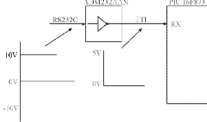
Fig. 9. Schematic diagram of the RS232C control circuit.
4.2.4 PIC Oscillator Circuit
To make do the operation of PIC, a clock generator is needed. An oscillation had within PIC, so, it puts a vibra- tor outside only. As the vibrator, the crystal oscillator can be used because of the precision oscillation. However, at the circuit this time, a ceramic vibrator (Resonator) is used because it does not need the precision oscillation. The maximum clock frequency of PIC16F873 is upto
20MHz. However, at the equipment this time, because it does not need high-speed operation, the oscillation fre-
quency is 4MHz. A transmission speed is calculated by
4MHz. So, when using this equipment at the clock fre-
quency which is not 4MHz, reconsideration is needed.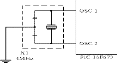
Fig. 10. Schematic Diagram of the PIC Clock Circuit
4.2.5 Power Circuit
The power to operate the display unit is supplied from the console unit through the cable. The DC +12V is made with AC +220V by the switching power circuit. The sup- plied voltage from the console unit is +12V. The +12V can be used for the LED displaying. The power of PIC needs the +5V. A three-terminal regulator is used for the voltage change from +12V to +5V. The +5V is used for PIC16F873 and decoder IC. The regulator can be used as the 100mA type regulator.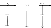
Fig. 11. Schematic Diagram of the Power Circuit
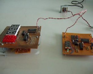
The peripheral interface controller based the remote dis- play system is shown in Fig. 12. The step-down transfor- mer is used to change from the AC 220V to the 12V. The Fig. 12 is the figure that is before the power supply is off and the data is not being sent from the console unit to the display unit of the remote display system.
Fig. 12. The PIC based remote display system.
IJSER © 2011 http://www.ijser.org
International Journal of Scientific & Engineering Research Volume 2, Issue 4, April-2011 8
ISSN 2229-5518
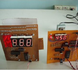
When the number 450 and the character A is sent from the console unit, the data that is sent from the console unit is shown in Fig. 13.
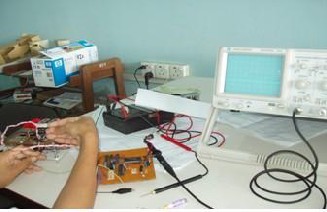
Fig. 15. Testing the received voltage level at the display unit.
Fig. 13. Testing the receiving data both console unit and display unit in remote display system.
The Fig. 14 shows the display portion of the remote display system.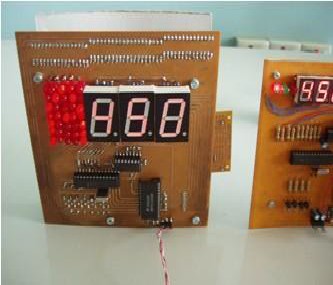
Fig. 14. The display unit with the data receiving process. The supply voltage of the display unit is supplied from
the console unit of the remote display system. Fig. 15
shows the testing of received voltage level at the display
unit.
This research describes about the display unit of the re- mote display system. The peripheral interface controller based remote display system can be used to inform the people. In this project, the display unit is constructed, one of the nearest, most versatile and most useful LED array, to view alphabetic character and numeric characters. In this research, the three kinds of characters and the three digits numbers are displayed. The PIC16F873 controls the numbers and the characters. The display unit of peripher- al interface controller based remote display system is de- signed to construct using with the devices which can buy easily in the market, easy to use and familiar with a per- son who interested in electronics field. This system is de- signed for English language capital letters and numbers. This thesis is not only applied for the educational aid for the beginner to learn the design, programming and de- velopment of the applications which use the PIC but also applied for displaying the number in many fields such as clinic, bank and financial institutions, interviewing com- mittees to call the candidates and etc.
As further extension, the remote display system is used 15m length between the console unit and the display unit in this research. For more distance, the various kinds of RS232 interface can be used. In large area of display, it can be used the largest size of seven-segment LED. By this way, the resolution of the display is smooth. Instead of LED, LCD can be used in this research. In this research, the digit display part of the display unit is made to light up by one digit to suppress an electric current. It can be made to light up the digits at the same time. It can be used to hold the display data by latch register (74LS273). The latch register is placed between the peripheral inter- face controller and the segment selecting circuit. The re- mote display system can be widely used in many fields that need to give information to users or partners. To de- velop the display technique and devices, people should
IJSER © 2011 http://www.ijser.org
International Journal of Scientific & Engineering Research Volume 2, Issue 4, April-2011 9
ISSN 2229-5518
study this technology. The development of this project intended the display unit of the remote display system to be used in various fields.
Firstly the author would like to thank her parents for their best wishes to join the Ph.D research. The author would like to ex- press the heart-felt gratitude to Daw Atar Mon for her leader- ship and advice, Daw Khin Sandar Tun for guidance in her re- search and U Tun Tun Win for suggestions on how to design the remote token display system. The author greatly expresses her thanks to all persons who will concern to support in prepar- ing this paper and her research.
[1] V.Rajarama and Mohan Ingle, “Electronic Project Volume-16”, An EFY Enterprise Publication, 1995.
[2] BEL Application Lab, “Electronic Project Volume-8”, An EFY Enter- prise Publication, 1987.
[3] Inoue, S, “Remote Display System”, PIC Circuit Gallery, October 2005. [4] “Data Sheet PIC16F873 28/40-Pin 8-bit CMOS FLASH Microcontrol-
lers”, <http://www.microchip.com>
[5] “+5V-Powered, Multichannel RS-232 Drivers/Receivers.”
<http://www.maxim.ic.com/packages>
[6] “Data Sheet of 74HC/HC154 4-to-16 Line Decoder/Demultiplexer”, September, 2004. <http://www.philips.com>
[7] http://www.Datasheet 4u.com
[8] Thomas L. Floyd, “Electronic Devices I, 4th Edition”, Prentice Hall
International, Inc, 1996.
[9] Thomas L. Floydm, “Electronic Devices II. 4th Edition”, Prentice Hall
International, Inc, 1996.
[10] Thomas E.Kissell, “Industrial Electronics”, Printed in the Republic of
Singapore, Prentrice-Hall International Editions.
[11] Thomas C.Hayes Paul Horowitz, “Student Manual for the Art of Elec- tronic”, Printed in Great Britain at the University Press, Cambridge.
[12] Nashelsky, L.and Boylestad, R.L., “Electronic Devices and Circuit
Theory. 8th Edition”, U.S.A. Prentice Hall, Inc. 2002.
[13] Boylestand, R., “Electronic Devices and Circuit Theory, Fifth Edition”, Printed by Prentice-Hall International, Inc.
[14] http://www.interq.jp.au.com
[16] http://ww w.st.com
[17] http://www.datasheetarchive.com
IJSER © 2011 http://www.ijser.org