
generate random sequence to improve coding performance.
International Journal of Scientific & Engineering Research Volume 2, Issue 7, July-2011 1
ISSN 2229-5518
Performance of Alamouti Space Time Coding in
Fading Channels for IEEE 802.16e Protocol
Lavish Kansal, Ankush Kansal, Kulbir Singh
Abstract - In this paper, a general Alamouti space time block code structure is proposed for multiple-input multiple-output–orthogonal frequency- division multiplexing (MIMO-OFDM) in W iMAX systems for 2 X NR antenna configurations. The signal detection technology used in this paper for MIMO-OFDM system is Zero-Forcing Equalization (linear detection technique). The analysis of Signal to Noise Ratio (SNR) vs Bit Error Rate (BER) for MIMO in W iMAX system has been done. For this purpose modulation technique QPSK has been considered for different convolution-codes (CC)-rates. Also Reed-Solomon (RS) codes have been implemented along with CC codes. Comparisons between ideal channel, Additive W hite Gaussian Noise (AW GN) and practical fading channel, Rayleigh channel has been done. Also the comparison is provided on the basis of SNR vs BER graph for different antenna configurations.
—————————— • ——————————
mong the emerging technologies for broadband wireless access, IEEE 802.16e is one of the most promising and attractive candidates. However, it also presents very challenging aspects in terms of radio resource management which intentionally left open to
implementers [1]. The IEEE
802.16e air interface standard [2] is based on orthogonal frequency-division multiplexing (OFDM), which has been regarded as an efficient way to combat the inter-symbol interference (ISI) for its excellent performance over frequency selective channels for broadband wireless networks. Multi-Input Multi- Output (MIMO) technology has also been recognized as a key approach for achieving a dramatic increase in the capacity of wireless communication systems [3].
In particular, the use of OFDM technology combined with MIMO is an attractive solution for future
-------------------------------------------------------
• Lavish Kansal is currently pursuing his Masters of Engineering from Thapar University, Patiala, India, Email: - lavish.s690@gmail.com
• Ankush Kansal is currently Assitant Professor in Electronics & Communication Engineering Department, Thapar University, Patiala, India, Email: - akansal@thapar.edu.
broadband wireless systems that require reliable and high-rate data transmission. The inherent structure of
MIMO-OFDM allows the use of dynamic resource allocation of subcarriers, bits, power and antennas which will improve the system performance remarkably.
Currently, Worldwide Interoperability for Microwave Access (WiMAX) has received much attention. It is based on the IEEE 802.16e standard and can be classified into Fixed WiMAX [4] and Mobile WiMAX . October 2007, wireless broadband technology, WiMAX, was formally adopted to be one of the 3G standards by International Telecommunication Union (ITU), which is a milestone in the development of WiMAX. For 802.16e MAC & PHY layers has been defined, but for present work only PHY has been taken into consideration. PHY layer for mobile WiMAX (IEEE-802.16e) has scalable FFT size128-2048 point FFT with OFDMA, Range is from 1.6 to 5 Km. at 5Mbps in
5MHz. channel BW, it supports 100Km/hr speed.
The block diagram for Wi-MAX system (standard:
802.16e) is shown in figure 1 [5]. Now we will take each block one by one in detail and in present paper simulation has been done for each block separately.
Randomization is the first process carried out in layer after the data packet is received from the higher layers each burst in Downlink and Uplink is randomized. It is basically scrambling of data to
IJSER © 2011 http://www.ijser.org
International Journal of Scientific & Engineering Research Volume 2, Issue 7, July-2011 2
ISSN 2229-5518
generate random sequence to improve coding performance.
Physical Layer Interface
Randomization
Derandomization
Downlink
FEC Encoding
Bit Level
Processing
FEC Decoding
Uplink
Interleaving
Deinterleaving
Symbol Mapping Symbol Demapping
Synchronization &
Pilot Insertion
OFDM Symbol Level Processing
Channel Estimation & Equalisation
IFFT
Desubchannelization & Pilot Extraction
Cyclic Prefix
FFT
Remove Cyclic Prefix
Figure 1:- WiMAX Model for Physical layer (802.16)
In Forward Error Correction (FEC) there are number of coding system like RS codes, convolution codes Turbo codes etc. But in the present paper only RS codes and convolution codes has been taken for simulation.
RS codes basically add redundancy to the data .this redundancy improves Blocks error. RS-encoder is based on Galois field computation to add the
redundancy bits. Wi-MAX is based on GF (28) that corresponds to as RS (N = 255, K = 239, T =8)
where:
K = Data Bytes before encoding
T - Number of bytes that can be corrected
IJSER © 2011 http://www.ijser.org
International Journal of Scientific & Engineering Research Volume 2, Issue 7, July-2011 3
ISSN 2229-5518
In this coding two polynomials are required namely code generator polynomial g(x)and field generator polynomial p(x) .For Wi-MAX system
Code generator polynomial
(x) = (x + k )(x + )(x + 2 ) ……..
… … (x + 2T- ) (1)
Field generator polynomial
P(x) = x8 + x4 + x3 + x2 + 1 (2)
Convolutional codes are commonly specified by three
parameters n, k, m. Where n is the number of output bits, k is the number of input bits and m is the number of memory registers. Encoder for a convolutional code accepts k-bit blocks of information sequence and produces an encoded sequence (codeword) of n-bit blocks. However, each encoded block depends not only on the corresponding k-bit message block at the same time unit, but also on M previous blocks. Hence, the encoder has a memory length of m. Encoder operates on the incoming message sequence continuously in a serial manner.
The quantity k/n called the code rate, is a measure of code’s efficiency. Other important parameter of convolutional code is the constraint length of the code and is defined by L= k*(m- 1) The constraint length L represents the number of bits in the encoder memory that affect the generation of the n output bits. The error correction capacity is related with this value. The
number of bits’ combinations in the registers is called the states of the code and are defined by number of states Ns = 2L, where L is the constraint length of the code.
Interleaving aims to distribute transmitted bits in time or frequency or both to achieve desirable bit error distribution after demodulation. What constitutes a desirable error distribution depends on the used FEC code. What kind of interleaving pattern is needed depends on the channel characteristics. If the system operates in purely AWGN environment, no interleaving is needed, because the error distribution cannot be changed by relocating the bits.
Communication channels are divided into fast
and slow fading channels. A channel is fast fading if the
impulse response changes approximately at the symbol rate of the communication system, whereas a slow fading channel stays unchanged for several symbols.
Modulation and channel coding are fundamental components of a digital communication system. Modulation is the process of mapping the digital information to analog form so it can be transmitted over the channel. Consequently every digital communication system has a modulator that performs this task. Closely related to modulation is the inverse process, called demodulation, done by the receiver to recover the transmitted digital information. The design of optimal demodulators is called detection theory. Different coherent mapping used are BPSK, QPSK and M-QAM .However there is trade-off between, different Mapping tech and spectral efficiency. In present paper all mappings are used for simulation purpose.
Pilot insertion is used for channel estimation &
synchronization purpose.
An inverse Fourier transform converts the frequency domain data input to time domain representing OFDM Subcarrier. IFFT is useful for OFDM because it generates samples of a waveform with frequency component satisfying orthogonality condition. It also removes the need of oscillator. A
general N-to-N point linear transformation requires N2
multiplications and additions. This would be true of the DFT and IDFT if each output symbol were calculated separately.
However, by calculating the outputs simultaneously and taking advantage of the cyclic properties of the multipliers e±j2nkn/N Fast Fourier Transform (FFT) techniques reduce the number of computations to the order of N log N. The FFT is most efficient when N is a power of two. Several variations of the FFT exist, with different ordering of the inputs and outputs, and different use of temporary memory.
One way to prevent IS1 is to create a cyclically extended guard interval, where each OFDM symbol is preceded by a periodic extension of the signal itself.
IJSER © 2011 http://www.ijser.org
International Journal of Scientific & Engineering Research Volume 2, Issue 7, July-2011 4
ISSN 2229-5518
Considering the discrete time implementation of the Multi Carrier system, sampling the transmitted Multi Carrier signal at a rate equal to the data rate one obtains a frame structure composed of the IDFT of the data symbols and of a cyclic prefix and where the OFDM frame will contain Ntotal = L + N samples. Here L is the number of samples copied from the end of N sample IDFT frame and glued at the start of each IDFT frame.
At the receiver, removing the guard interval becomes equivalent to removing the cyclic prefix, while the effect of the channel transforms into the periodic convolution of the discrete time channel with the IDFT of the data symbols. Performing a DFT on the received
samples after the cyclic prefix is discarded, the
In radio communications MIMO means multiple antennas both on transmitter and receiver side of a specific radio link. In case of spatial multiplexing different data symbols are transmitted on the radio link by different antennas on the same frequency within the same time interval.
Multipath propagation is assumed in order to ensure the correct operation of spatial multiplexing, since MIMO is performing better in terms of channel capacity in a rich scatter multipath environment than in case of environment with LOS (line of sight). This fact was spectacularly shown in [6]. MIMO transmission can be characterized by the time variant channel matrix:
periodic convolution is transformed into multiplication, as it was the case for the analog Multi Carrier receiver.1/2 or 1/4 or1/8 or 1/16 or 1/32 times of
h , (r, t) h ,2 (r, t)
H(r T)= h2, (r, t)
. h ,NR (r, t)
data symbol is added at beginning of the OFDM.
hNT, (r, t) …
. hNT,NR (r, t)
(3)
Multi-antenna systems can be classified into three main categories. Multiple antennas at the transmitter side are usually applicable for beam forming purposes. Transmitter or receiver side multiple antennas for realizing different (frequency, space) diversity schemes. The third class includes systems with multiple transmitter and receiver antennas realizing spatial
multiplexing (often referred as MIMO by itself).
where the general element, hnt,nr (T, t) represents the complex time-variant channel transfer function at the path between the nt-th transmitter antenna and the nr-th receiver antenna. NT and NR represent the number of transmitter and receiver antennas respectively.
![]()
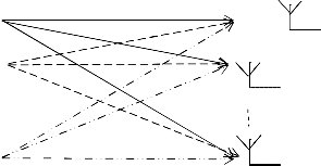
Transmitting antennas MIMO-channels Receiving antennas
Tx 1 Rx 1![]()
Tx 2 Rx 2![]()
![]()
Tx M Rx N
Figure 2:- Block Diagram of a generic MIMO system with M transmitters and N receivers
Derived from Shannon’s law, for the capacity of MIMO channel the following expression was proven in [6] and [7]:
IJSER © 2011 http://www.ijser.org
International Journal of Scientific & Engineering Research Volume 2, Issue 7, July-2011 5
ISSN 2229-5518
max (det(I + HRssHH)) (4)
1 ( O ) H
( O )
C = ( ss) 2
![]()
![]()
= 2 P (H
H )ss
(9)
s
1 K
( H(
( O ) H( k ) 2
L Pk
H
H(O)H
)ss
2 k=1
( O ) H
where H denotes the channel matrix and HH its
transpose conjugate, I represents the identity matrix
and Rss the covariance matrix of the transmitted signal
s.
(H H(O))ss
where (.)ss denotes the sth row and sth column element of the matrix within the braces. Note the transmit power is shared between two antennas and hence the power is scaled by 2. The signal power and interference power are given as
In this case, there are two antennas at the transmitter
f(.) =
![]()
(H ( k ) H H ( k ) )ss (10)
H
)ss
side and NR receiving antennas at the receiver side [8].![]()
and g(.) =
(H (k)
(O)
![]()
(O)H ( k )
H
(11)
First, consider the signal model received at a receiver
side with a single receive antenna, i.e. NR = 1. In this
2 (H (O)H
(O))ss
case, the received signal can be represented in the following form
Next the STC Alamouti scheme can be extended to any
number of receive antennas, NR � 2 , by row appending![]()
![]()
(stacking) channel matrix from each receiver. Hence, now the equivalent matrix would be
�y = Po H ( k ) x0 + LK
Pk ( k )![]()
![]()
2 k== 2 H
xk + n (5)
H ( k ) = [H(k)
. . . . . . . (k )
where x, y and n are transmit, receive and noise vectors respectively (with zero mean and variance a2, circularly symmetric normal distributed entries), and Hk is the Nt X Nr channel matrix, K is the number of interferers and Pk is the received power from the Kth receiver and is given by:
2 N
Where ( k ) is the equivalent Alamouti matrix to the
n h antenna.
![]()
Pk = PT GK k Xk/ k
L(dk)
(6)
Signal detection of MIMO-OFDM system can be
here PT is the transmit power, Xk is the log normal shadowing, L(dk) is the path loss at the distance dk , and
Gk is the aggregate antenna gain. H ( k ) is an equivalent
channel matrix given by
(k) h(k)
carried out by various sub-carrier channel signal
detection. Although the whole channel is a frequency- selective fading, but various sub-carriers channel divided can be regarded as flat fading, so the flat
fading MIMO signal detection algorithm for MIMO-
H ( k ) = hk,k
k, (7)
OFDM system can be directly into the detection of all
(k) -h(k)
hk,
k,k
sub-channels, and signal detection algorithm of the corresponding MIMO-OFDM system can be obtained.
We then premultiply the received vector with the
transpose conjugate of the equivalent channel matrix
Similarly, the other optimization algorithms used in flat fading MIMO signal detection can also be leaded
for an MRC receiver, i.e., w = H ( k )
z = w* �y
. Thus, we have that
into the MIMO-OFDM system.
![]()
= Po H ( k ) H H ( k ) x0 + LK![]()
Pk ( k ) H ( k )
( k ) H
Zero Forcing algorithm is regard the signal of each![]()
2
(8)![]()
k== 2 H
H xk + H n
transmitting antenna output as the desired signal, and regard the remaining part as a disturbance, so the mutual interference between the various transmitting
The SINR on the stream is given as follows
IJSER © 2011 http://www.ijser.org
International Journal of Scientific & Engineering Research Volume 2, Issue 7, July-2011 6
ISSN 2229-5518
antennas can be completely neglected. The specific algorithm is as follows:
For k = 0,1,………….,K-1, so that,
Y(k) = [Y1(k),Y2(k),…….……..,YN(k)]T (13)
X(k) = [X1(k),X2(k),…………….,XM(k)]T (14)
N(k) = [N1(k),N2(k),……...……,NN(k)]T (15)
system. Its equivalent block diagram is shown in
Figure 3.
Therefore, signal detection can be transformed into K sub-channels in their signal detection to complete in MIMO-OFDM system and each sub-channel detection of the above can be used flat fading MIMO channel to achieve the detection algorithm. Zero-forcing (ZF) detection algorithm for MIMO detection algorithm is
the most simple and basic algorithms, and the basic
H( ) H( ) 2
H(k) = H( )2 H( )22
… H( ) M
… H( )2M (16)
idea of zero forcing algorithm is get rid of MIMO- channel interference by multiplying received signal and the inverse matrix of channel matrix . Zero-
H( )N H( )N2 … H( )NM
Here Y(k), X(k), N(k) respectively express output signal,
the input signal and noise vector of the k sub-channels in MIMO-OFDM system, for M transmitting antennas and N receiving antennas, H(k) expresses channel matrix of the k sub-channels, mathematical expression of sub-channel in the MIMO-OFDM system is as follows:
Y(k) = H(k)X(k) + N(k) (17)
Forcing solution of MIMO-OFDM system is as follows:
XZF = H-1 Y = X + H-1 N (18)
In which H-1 is the channel matrix for the generalized inverse matrix, the type is obtained for hard-decision demodulation after that to be the source signal estimates:
X ZF = E(XZF) (19)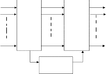
There is a linear relationship between input signal X(k) and output signal Y(k), that is similar to the flat fading channel for each subcarrier channel in MIMO-OFDM
X Y1(k) X (k)
X2(k)
Sub- carrier channel H(k)
Y2(k)
Sub- channel detection
X2(k)
XM(k) YN(k) X (k)
Channel
Estimation
Figure 3:- Baseband block diagram of k subcarrier channel in MIMO-OFDM system
IJSER © 2011 http://www.ijser.org
International Journal of Scientific & Engineering Research Volume 2, Issue 7, July-2011 7
ISSN 2229-5518
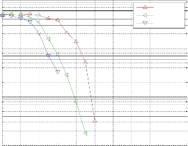
Figure 4:- SNR vs BER plot for QPSK with ½ code rate for AWGN channel employing MIMO-OFDM in WiMAX Physical Layer
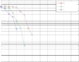
In figure 5, the performance the analysis using same channel and same modulation is shown but, using different code rate for convolution coding i.e. 3/4.
SNR vs BER plot for QPSK with 3/4 code rate for AW GN channel
0
10
1Tx X 1 Rx
2Tx X 1Rx
2Tx X 2Rx
-1
10
-2
10
The WiMAX system is implemented according to the table 1 [10]. Then, the data output of the down link is transmitted using the alamouti space time coding using 2 transmitting antennas. At, the receiver side the input data is detected using the Zero Forcing Algorithm. The analysis is done on the basis of SNR vs BER graph for AWGN and Rayleigh channels.
In figure 4, SNR vs BER performance of QPSK
modulation using ½ convolution code rate is shown in
AWGN channel.
-3
10
0 2 4 6 8 10 12 14 16 18 20
signal to noise ratio
Figure 5:- SNR vs BER plot for QPSK with 3/4 code rate for AWGN channel employing MIMO-OFDM in WiMAX Physical Layer
In figure 6, SNR vs BER performance of QPSK modulation using ½ convolution code rate is shown in Rayleigh channel.
SNR vs BER plot for QPSK with 1/2 code rate for AWGN channel
0
10
1Tx X 1 Rx
2Tx X 1Rx
2Tx X 2Rx
SNR vs BER plot for QPSK with 1/2 code rate for RAYLEIGH channel
0
10
1Tx X 1 Rx
2Tx X 1Rx
2Tx X 2Rx
-1
-1 10
10
-2
-2 10
10
-3
10
0 2 4 6 8 10 12 14 16 18 20
signal to noise ratio
-3
10
0 2 4 6 8 10 12 14 16 18 20
signal to noise ratio
IJSER © 2011 http://www.ijser.org
International Journal of Scientific & Engineering Research Volume 2, Issue 7, July-2011 8
ISSN 2229-5518
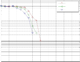
Figure 6:- SNR vs BER plot for QPSK with 1/2 code rate for Rayleigh channel employing MIMO-OFDM in WiMAX Physical Layer
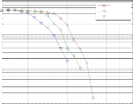
In figure 7, the performance the analysis using same channel and same modulation is shown but, using different code rate for convolution coding i.e. 3/4.
SNR vs BER plot for QPSK with 3/4 code rate for RAYLEIGH channel
0
10
1Tx X 1Rx
2Tx X 1Rx
2Tx X 2Rx
-1
10
-2
10
-3
10
0 2 4 6 8 10 12 14 16 18 20
signal to noise ratio
Figure 7:- SNR vs BER plot for QPSK with 3/4 code rate for Rayleigh channel employing MIMO-OFDM in WiMAX Physical Layer
In this paper effect of employing MIMO space time coding in 802.16e PHY layer has been simulated along with mathematical analysis. Both ideal (AWGN) and practical (Rayleigh) channels has been analyzed. Results have shown that in both cases as we goes on increasing the no. of transmitters or receiver the BER decreases. BER is higher for SISO system, but when we employ the MIMO in WiMAX the BER decreases proportionally with increase in number of antennas.
Also the BER is higher for the system employing 3/4 convolutional code as compared to the system employing 1/2 code rate.
[1] Radio resource management and protocol engineering for IEEE 802.16. Page(s): 36-43, IEEE Wireless Communications. February 2007.
[2] IEEE standard for Local and Metropolitan Area Networks-Part 16: Air interface for Fixed Broadband Wireless Access Systems, IEEE Std.
802.16, Rev. 2004, Oct. 2004
[3] G.J. Foschini and M.J. Gans, “On limits of wireless communications in a fading environment when using mutiple antennas”, Wireless Personal Communication, vol.6, no.3, pp.311-335, March
1998.
[4] IEEE standard 802.16-2005, IEEE standard for Local and Metropolitan Area Networks-Part16: Air Interface for Fixed and Mobile Broadband wireless Access system, Feb 2006.
[5] M. N. Khan and S. Ghuari, “The WiMAX 802.16e Physical Layer Model”, International Conference on Wireless, Mobile and Multimedia Networks, pp
117-120, 2007.
[6] A. van Zelst and T. C. W. Schenk, “Implementation of a MIMO OFDM-Based Wireless LAN System,” IEEE Transaction on Signal Processing, Vol. 52, no. 2, pp 483-494, February 2004.
[7] D. S. Shiu, G. J. Foschini, M. J. Gans, and J. M. Kahn, “Fading correlation and its effect on the capacity of multi element antenna systems”, IEEE Transactions on Communications, vol. 48, no. 3, pp. 502–513, 2000.
[8] S. P. Alex and L. M. A. Jalloul, “Performance Evaluation of MIMO in IEEE802.16e/WiMAX”, IEEE Journal of Selected Topics in Signal Processing, VOL. 2, NO. 2, pp 181-190, APRIL
2008.
[9] X. Zhang , Y. Su and G. Tao, “Signal Detection Technology Research of MIMO-OFDM System” In Proceeding International Congress on Image and Signal Processing, Vol.7, Issue 11,pp 3031-
3034, (Yantai) 2010.
[10] S. Ahson and M. Ilyas, “WiMAX Applications”, CRC Press 2006.
IJSER © 2011 http://www.ijser.org
International Journal of Scientific & Engineering Research Volume 2, Issue 7, July-2011 9
ISSN 2229-5518
USER© 2011