International Journal of Scientific & Engineering Research, Volume 6, Issue 1, January-2015 2045
ISSN 2229-5518
1Principal, Dungarpur College of Engineering and Technology, (Rajasthan), India
2Assistant Professor, M.E. Department, Dungarpur College of Engineering and Technology,Dungarpur Rajasthan, India amittiwari992@gmail.com,
4Institute of Technology & Management, Gwalior (M.P.), India
Turbochargers are used throughout the automotive industry as they can enhance the output of an internal combustion (IC) engine without the need to increase its cylinder capacity. .The emphasis today is to provide a feasible engineering solution to manufacturing economics and “greener” road vehicles. It is because of these reasons that turbochargers are now becoming more and more popular in automobile applications. The new turbocharger is coupled to an air-water intercooling system to decrease the inlet air temperatures. This project analyzed the intercooling system and tested the final design in the vehicle. The results show that the cooling system components purchased are adequate for this system. The aim of this paper is to provide are view on the techniques used in turbocharging used in two stroke single cylinder petrol engine by this to increase the engine output and reduce the exhaust emission levels. This paper is to analyze a turbocharger system in a two stroke petrol engine. The ideal turbocharger design would be smaller than the system purchased. The paper will also create speed sheets for use in calculating the necessary parameters for another turbocharger system, or to modify the current system..
A turbocharger consists of a compressor and a turbine linked by a shared axle so if the turbine rotates, the compressor also rotates. The turbine inlet receives exhaust gases from the engine causing it to rotate. This rotation in turn drives the compressor, which compresses the ambient air and delivers it to
the intake manifold of an engine at higher pressure, resulting in greater amount of air entering the
IJSER © 2015 http://www.ijser.org
International Journal of Scientific & Engineering Research, Volume 6, Issue 1, January-2015 2046
ISSN 2229-5518
cylinder. There are two ways of increasing the power of an engine. One of them would be to make the fuel-air mixture richer by adding more fuel. This will increase the power but at the cost of fuel efficiency and increase in pollution levels prohibitive. The other would be to somehow increase the volume of air entering into the cylinder and increasing the fuel intake proportionately, increasing power and fuel efficiency without hurting the environment or efficiency. This is exactly what Turbochargers do; increasing the volumetric efficiency of an engine in a naturally aspirated engine, the downward stroke of the piston creates an area of low pressure in order to draw more air into the cylinder through the intake valves. The ability to fill the cylinder with air is its volumetric efficiency. Now if we can increase the pressure difference across the intake valves by some way we can make more air enter into the cylinder and hence increasing the volumetric efficiency of the engine. A turbocharger does exactly this, it increases the pressure at the point where air is entering the cylinder, thereby increasing the pressure difference across the intake valves and thus more air enters into the combustion chamber. The additional air makes it possible to add more fuel, increasing the power and torque output of the engine, particularly at higher engine speeds. If the pressure in the cylinder goes too high it will cause the fuel to pre-ignite (remember more pressure = more temperature) in turn causing serious physical damage to the engine. To regulate pressure or boost, a waste gate is used. The application of a compressor to increase pressure at the point of air intake is also commonly referred to as forced induction. That is why in turbocharged cars, you feel the turbo kicking in after certain rpm is reached, at which point the exhaust system overcomes the rotational inertia of the turbine and speed it up to supply boost pressure
Cummins Turbo Technologies New Technology Developments
1. 1986 Turbocharging made a step change in efficiency with patented Map Width Enhancement technology increasing the range of the compressor by 20%.

IJSER © 2015 http://www.ijser.org
International Journal of Scientific & Engineering Research, Volume 6, Issue 1, January-2015 2047
ISSN 2229-5518
2. 1988 3D viscous flow analysis programme introduced to reduce aerodynamic analysis from 13 weeks to less than oneweek.
3. 1990 The first European heavy-duty wastegate turbocharger was released in production. The first commercial automotive turbocompound engine was released with Scania with additional Holset Power Turbine downstream of the turbocharger to deliver significantly improved fuel consumption.
4. 1998 The Worldwide Technical Centre was opened and the world's first sliding-wall variable geometry turbocharger (Holset VGTTM) was launched.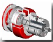
5. 2009 A prototype turbine expander unit was developed for waste heat recovery systems.

6. 2011 A waste heat recovery test cell opened in Huddersfield, the first of its kind in the world.
IJSER © 2015 http://www.ijser.org
International Journal of Scientific & Engineering Research, Volume 6, Issue 1, January-2015 2048
ISSN 2229-5518
7. 2012 Future technologies launched including Waste Heat Turbine Expander, Next Generation
Holset VGTTM , Next Generation Two-Stage System and Next GenerationComponents.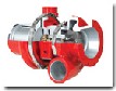
8. 2014Introduction of the Series 900 to the already robust and flexible large product range, Series
800 and Series 1000, creating the most efficient and diverse turbochargers we have ever produced for
the 16 litre and above engine range.
There are two types of choices in a carburetor turbo setup: “suck-through” or “blow through”. The suck-through (or draw through) set up involves mounting the carburetor before the turbine inlet (usually in front of the impeller mouth). This means that both fuel and air are drawn into the turbo already mixed and then blown into the inlet manifold. This is by far the simplest way to setup a turbo as; the carburetor doesn’t need to be especially modified turning quit essay. The main disadvantage are that you can’t use any intercooling with such a setup, as it is dangerous to run air/fuel mixture through as an intercooler core. The reason for this is that fuel can condense inside the intercooler core and stay there- if you then have an engine back fire the intercooler can explode. As a result water injection is about the only option for cooling the charger air with this setup. This also corresponds to a blow-off valve because instead of just venting pressurized air, it would be releasing a fuel/air mixture which is very dangerous. The blow-through arrangement, logically enough, means the carburetor is mounted after the turbo compressor, so the turbo only draws in air and then blow it through the carburetor, which adds the fuel. The good things is than an intercooler and also a blow-off valve can be used with such setup.
All naturally aspirated Otto and diesel cycle engines rely on the downward stroke of a piston to create a low pressure area (less than atmospheric pressure) above the piston in order to draw air through the
intake system. With the rare exception of tuned induction systems, most engines cannot inhale their
IJSER © 2015 http://www.ijser.org
International Journal of Scientific & Engineering Research, Volume 6, Issue 1, January-2015 2049
ISSN 2229-5518
full displacement of atmospheric density air. The measure of this loss or inefficiency in four stroke engines is called volumetric efficiency. If the density of the intake air above the piston is equal to atmospheric, then the engine would have 100% volumetric efficiency. Unfortunately, most engines fail to achieve this level of performance.
This loss of potential power is often compounded by the loss of density seen with elevated altitudes. Thus, a natural use of the turbocharger is with aircraft engines. As an aircraft climbs to higher altitudes the pressure of the surrounding air quickly falls off. At 5,486 m (18,000 ft) the air is at half the pressure of sea level which means that the engine will produce less than half-power at this altitude. A turbocharger may also be used to increase fuel efficiency without any attempt to increase power. It does this by recovering waste energy in the exhaust and feeding it back into the engine intake. By using this otherwise wasted energy to increase the mass of air it becomes easier to ensure that all fuel is burnt before being vented at the start of the exhaust stage. The increased temperature from the higher pressure gives a higher Carnot efficiency.
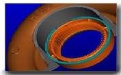
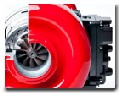
Turbine housings are manufactured in various grades of spherical graphite iron to deal with thermal fatigue and wheel burst containment. As with the impeller, profile machining to suit turbine blade shape is carefully controlled for optimum performance. The turbine housing inlet flange acts as the reference point for fixing turbocharger position relative to its installation. It is normally the load bearing surfaces.
Fig 4.1.1:- Turbine housing
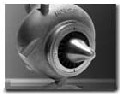
The Turbine Wheel is housed in the turbine casing and is connected to a shaft that in turn rotates the compressor wheel.
IJSER © 2015 http://www.ijser.org
International Journal of Scientific & Engineering Research, Volume 6, Issue 1, January-2015 2050
ISSN 2229-5518
Fig 4.1.2:- Wheel
Compressor housings are also made in cast aluminum. Various grades are used to suit the application. Both gravity die and sand casting techniques are used. Profile machining to match the developed compressor blade shape is important to achieve performance consistency.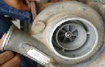
Fig4.1.3:- Compressor cover
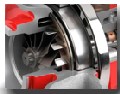
Compressor impellers are produced using a variant of the aluminum investment casting process. A rubber former is made to replicate the impeller around which a casting mould is created. The rubber former can then be extracted from the mould into which the metal is poured. Accurate blade sections and profiles are important in achieving compressor performance. Back face profile machining optimizes impeller stress conditions. Boring to tight tolerance and burnishing assist balancing and
fatigue resistance. The impeller is located on the shaft assembly using a threaded nut.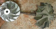
Fig4.1.4:- Compressor wheel and turbine impeller
IJSER © 2015 http://www.ijser.org
International Journal of Scientific & Engineering Research, Volume 6, Issue 1, January-2015 2051
ISSN 2229-5518
The Blow-Off valve (BOV) is a pressure relief device on the intake tract to prevent the turbo compressor from going into surge. The BOV should be installed between the compressor discharge and the throttle body, preferably downstream of the charge air cooler (if equipped). When the throttle is closed rapidly, the airflow is quickly reduced, causing flow instability and pressure fluctuations. These rapidly cycling pressure fluctuations are the audible evidence of surge. Surge can eventually lead to thrust bearing failure due to the high loads associated with it. Blow-Off valves use a combination of manifold pressure signal and spring force to detect when the throttle is closed. When the throttle is closed rapidly, the BOV vents boost in the intake tract to atmosphere to relieve the pressure; helping to eliminate the phenomenon of surge.
Waste gates:-On the exhaust side, a Waste gate provides us a means to control the boost pressure of the engine. Some commercial diesel applications do not use a Waste gate at all. This type of system is called a free-floating turbocharger. However, the vast majority of gasoline performance applications require Waste gates. There are two (2) configurations of Waste gates, internal or external. Both internal and external Waste gates provide a means to bypass exhaust flow from the turbine wheel. Bypassing this energy (e.g. exhaust flow) reduces the power driving the turbine wheel to match the power required for a given boost level. Similar to the BOV, the Waste gate suses boost pressure and spring force to regulate the flow bypassing the turbine.
Internal Waste gate are built into the turbine housing and consist of a “flapper” valve, Crank arm, rod end, and pneumatic actuator. It is important to connect this actuator only to boost pressure; i.e. it is not designed to handle vacuum and as such should not be referenced to an intake manifold.
External Waste gates are added to the exhaust plumbing on the exhaust manifold or header. The advantage of external Waste gates is that the bypassed flow can be reintroduced into the exhaust stream further downstream of the turbine. This tends to improve the turbine’s performance. On racing applications, this Waste gated exhaust flow can be vented directly to atmosphere.
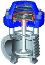
Fig4.1.5:- Waste gates
IJSER © 2015 http://www.ijser.org
International Journal of Scientific & Engineering Research, Volume 6, Issue 1, January-2015 2052
ISSN 2229-5518
Bearing Housing
Turbine Housing
Bearing System
Compressor Housing
Shaft and Wheel
Impeller
Electronic Compressor
Typically Grey(flake) cast iron(pearlitic)
Typically shell moulded cores to provide positional accuracy of bearing location and seals, shell mould or sand cast outer
Machined by a combination of milling, turning, drilling, tapering, honing.
Complex geometries – particularly for water
Cooled housing and variable geometry turbos
Requirements
• Castability
• Ease of machining
• Rigidity
• Thermal stability
Typically spheroidal graphite cast iron(ferritic)
Typically greensand mould, sand core
Profile machining to match the turbine blade shape
Normally the primary mounting point and load bearing interface for the whole turbo
Requirements
• Impact resistance (ductility)
• Oxidation resistance
• High temp strength
• Thermal fatigue resistance
Journal bearings
• Fully floating ring bearings- allows higher clearances, so higher oil flows for cooling
• Oil film thickness of 0.008 to 0.015mm
• Brass or leaded bronze
• Allow high degree of imbalance
IJSER © 2015 http://www.ijser.org
International Journal of Scientific & Engineering Research, Volume 6, Issue 1, January-2015 2053
ISSN 2229-5518
Thurst bearing
• Taper land bearing
• Phosphor bronze or sintered iron
• Thrust loads of 100-2000N- size dependent
• Typical oil film thickness 0.008-0.015mm
Typically cast aluminum alloy-various grades
Gravity die cast or sand cast
Profile matching to match impeller blade shape
Operation can be up to 200’C
Requirements
• Impact resistance(ductility)
• Ease of machining
High nickel super alloy
Blade profile machined
Friction welded to forged steel shaft
Very sensitive to balance grooves, and defects or damage
Requirements
• Fatigue strength
• Elevated temp strength
• Creep resistance
• Corrosion resistance
Other materials used on turbochargers (usually or niche applications)
• Titanium aluminide
• Ceramic (typically silicon nitride)
Typically cast aluminium alloy cast by a variant of investment casting process, using rubber formers and plaster moulds
Started using this process in 1976 to allow the production of wheels with backsweep on the blades
Operation up to more than 200’C possible
Requirements
• Fatigue strength
• Elevated temp strength
• Creep resistance
• Corrosion resistance
Very sensitive to balance groove shape and to damage/defects.
IJSER © 2015 http://www.ijser.org
International Journal of Scientific & Engineering Research, Volume 6, Issue 1, January-2015 2054
ISSN 2229-5518
A turbocharger is basically an air pump. Hot exhaust gases leaving the engine after combustion are routed directly to the turbine wheel side of the turbocharger to make it rotate. That turbine wheel is connected by a shaft to a compressor wheel. As the turbine wheel spins faster and faster, it causes the compressor wheel to also spin quickly. The rotation of the compressor wheel pulls in ambient air and
compresses it before pumping it into the engine’s chambers.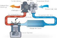
Fig4.6:-operation principle
The objective of a turbocharger is the same as that of a supercharger, to improve an engine's volumetric efficiency by solving one of its cardinal limitations. A naturally aspirated automobile engine relies mostly on the downward stroke of a piston to create an area of low pressure in order to draw air into the cylinder through one or more intake valves. The pressure in the atmosphere is no more than 1 atm (approximately 14.7 psi, or 1 bar), so there ultimately will be a limit to the pressure difference across the intake valves and thus the amount of airflow entering the chamber. Since the turbocharger increases the pressure at the point where air is entering the cylinder, a greater mass of air (oxygen) will be forced in as the inlet manifold pressure increases. The presence of additional air mass in the cylinder makes it possible to create a bigger explosion if more fuel is injected, increasing the power and torque output of the engine. Modern Group N Rally cars are forced by the rules to use a
34mm restrictor at the compressor inlet, which effectively limits the maximum boost (pressure above atmospheric) that the cars can achieve at high rpm. Interestingly, at low rpm they can reach boost pressures of above 22psi (1.5bar).
Engine power is proportional to the amount of air and fuel that can get into the cylinders. All things being equal, larger engines flow more air and as such will produce more power. If we want our small engine to perform like a big engine, or simply make our bigger engine produce more power, our ultimate objective is to draw more air into the cylinder. By installing a Garrett turbocharger, the power and performance of an engine can be dramatically increased. So how does a turbocharger get
more air into the engine? Let us first look at the schematic below:
IJSER © 2015 http://www.ijser.org
International Journal of Scientific & Engineering Research, Volume 6, Issue 1, January-2015 2055
ISSN 2229-5518
Fig4.7:- Turbo system working
1. Compressor Inlet
2. Compressor Discharge
3. Charge air cooler (CAC)
4. Intake Valve
5. Exhaust Valve
6. Turbine Inlets
7. Turbine Discharge
The components that make up a typical turbocharger system are:
• The air filter (not shown) through which ambient air passes before entering the compressor
(1)
• The air is then compressed which raises the air’s density (mass / unit volume) (2)
• Many turbocharged engines have a charge air cooler (aka intercooler) (3) that cools the compressed air to further increase its density and to increase resistance to detonation
• After passing through the intake manifold (4), the air enters the engine’s cylinders, which contain a fixed volume. Since the air is at elevated density, each cylinder can draw in an increased mass flow rate of air. Higher air mass flow rate allows a higher fuel flow rate (with similar air/fuel ratio). Combusting more fuel results in more power being produced for a given size or displacement
• After the fuel is burned in the cylinder it is exhausted during the cylinder’s exhaust stroke in to the exhaust manifold (5)
• The high temperature gas then continues on to the turbine (6). The turbine creates backpressure on the engine which means engine exhaust pressure is higher than atmospheric pressure
• A pressure and temperature drop occurs (expansion) across the turbine (7), which harnesses the exhaust gas’ energy to provide the power necessary to drive the compressor.
Mileage of Scooty ES
1. Overall Mileage 45 km per litre
IJSER © 2015 http://www.ijser.org
International Journal of Scientific & Engineering Research, Volume 6, Issue 1, January-2015 2056
ISSN 2229-5518
Analysis of engine and turbocharger
Engine Displacement | 59.90 cc |
Engine Type Single Cylinder | 2- stroke, forced air cooled |
Maximum Power | 3.5 bhp @ 5500 rpm |
Maximum Torque | 4.5 Nm @ 5000 rpm |
Inlet Temperature of turbine | Tti=76oc =349k |
Outlet temperature of turbine | Tto = 41.5oc =314k |
Inlet temperature of compressor | Tci= 33oc =306k |
Outlet temperature of compressor | Tco = 35.1oc =308k |
Tti=76oc =349k
Tto = 41.5oc =314k Tci= 33oc =306k Tco = 35.1oc =308k
Where:
Tti = Inlet Temperature of turbine Tto = Outlet temperature of turbine Tci= Inlet temperature of compressor
Tco = Outlet temperature of compressor
Power of turbocharger = turbine power – compressor power/ turbine power
Turbine power = mg×cpg(Tti-Tto)
= mg×1.05(349-314)
Here: Mg=ma+mf Ma/mf=18
Mg = {ma+(ma/18)}
IJSER © 2015 http://www.ijser.org
International Journal of Scientific & Engineering Research, Volume 6, Issue 1, January-2015 2057
ISSN 2229-5518
Turbine power ={ma+(ma/18)} ×1.05(349-314)
= 38.79ma
Compressor power=ma×cpa×(tco-tci)
= ma×1×(308-306)
= 2ma
Power of turbocharger =turbine power-compressor power/ turbine power
P=38.79ma-2ma/38.79ma
P= 0.9484Kj/Kg
P= 948.4j/Kg
Power of turbocharger is =948.4j/Kg
Engine Volumetric Flow Equation
Volume of air (cu ft/min)= engine rpm x engine cid
(1728 x 2)
=5500X 3.5663
(1728 x 2)
=5.8295 (cu ft/min)
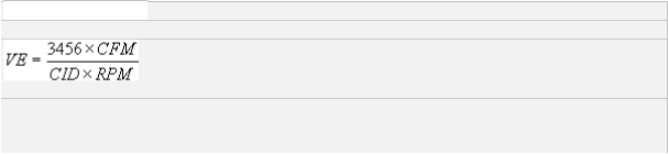
Volumetric Efficiency
VE=3456x3.57÷3.5663×5500 = 0.6290
= 62%
IJSER © 2015 http://www.ijser.org
International Journal of Scientific & Engineering Research, Volume 6, Issue 1, January-2015 2058
ISSN 2229-5518
The experiment of this project was done and reading was taken which are under as follow.
S.R. NO | ENGINE SPEED (RPM) | TURBINE SPEED(RPM) | AIR PRESSURE(BAR) |
1 | 0 | 0 | 0 |
2 | 500 | 65 | 0.15 |
3 | 1000 | 140 | 0.35 |
4 | 2000 | 300 | 0.75 |
5 | 3000 | 465 | 1.10 |
6 | 4000 | 625 | 1.60 |
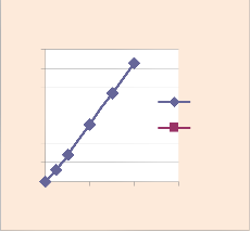
ENGINE SPEED Vs TURBINE SPEED
X axes:-Engine speed (rpm) Y axes:-turbine speed (rpm)
SR. NO. | ENGINE SPEED | TURBINE SPEED |
1 | 0 | 0 |
2 | 500 | 65 |
3 | 1000 | 140 |
4 | 2000 | 300 |
5 | 3000 | 465 |
6 | 4000 | 625 |
IJSER © 2015 http://www.ijser.org
International Journal of Scientific & Engineering Research, Volume 6, Issue 1, January-2015 2059
ISSN 2229-5518
![]()
Y 700
600
- 500
a 400
x 300
e 200
s 100
0
Y -V a lues
C olumn1
0 2000 4000 6000
X- axes
X axes:-Turbine speed (rpm) Y axes:-Pressure (bar)
SR. NO | TURBINE SPEED | TURBOCHARGER PRESSURE |
1 | 0 | 0 |
2 | 65 | 0.15 |
3 | 140 | 0.35 |
4 | 300 | 0.75 |
5 | 465 | 1.10 |
6 | 625 | 1.60 |
(1) More power compared to the same size naturally aspirated engine. Better thermal efficiency over naturally aspirated engine and supercharged engine because the engine exhaust is being used to do the useful work which otherwise would have been wasted.
IJSER © 2015 http://www.ijser.org
International Journal of Scientific & Engineering Research, Volume 6, Issue 1, January-2015 2060
ISSN 2229-5518
(2) Better thermal efficiency over both naturally aspirated and supercharged engine when under full load (i.e. on boost). This is because the excess exhaust heat and pressure, which would normally be wasted, contributes some of the work required to compress the air.
(3) Weight/Packaging. Smaller and lighter than alternative forced induction systems and may be more easily fitted in an engine bay.
(4) Fuel Economy. Although adding a turbocharger itself does not save fuel, it will allow a vehicle to use a smaller engine while achieving power levels of a much larger engine, while attaining near normal fuel economy while off boost/cruising. This is because without boost, less fuel is used to create a proper air/fuel ratio.
1. Lack of response called the Turbo Lag. If the turbo is too big, the boost will build up slowly because more exhaust pressure will be needed to overcome the rotational inertia on the larger turbine reducing throttle response but more peak power. If the turbo is too small the turbo lag won’t be as big but the peak power would be lesser. So the turbocharger size is a very important consideration when deciding on it for a particular engine.
2. Boost threshold- A turbocharger starts producing boost only above a certain rpm due to a lack of exhaust gas volume to overcome inertia of rest of the turbo propeller. This results in a rapid and nonlinear rise in torque, and will reduce the usable power band of the engine. The sudden surge of power could overwhelm the tires and result in loss of grip, which could lead to under steer/over steer, depending on the drive train and suspension setup of the vehicle. Lag can be disadvantageous in racing, if throttle is applied in a turn, power may unexpectedly increase when the turbo spools up, which can cause excessive wheel spin.
3. Cost- Turbocharger parts are costly to add to naturally aspirated engines. Heavily modifying OEM turbocharger systems also require extensive upgrades that in most cases requires most (if not all) of the original components to be replaced.
The future scope of turbocharger arrangement in the two stroke single cylinder petrol engines are improved fuel economy, reduced HC and CO emission, reduced noise due to lower rate of pressure rise and higher energy in the exhaust gases. This further decrease the density of air entering the cylinder because of high wall temperatures of the engine. in the present work for compensating the decrease in volumetric efficiency a single cylinder petrol engine is turbocharged to different inlet pressures depending upon the load and the performance of the engine under turbocharging condition is investigated. The variation of volumetric efficiency with power output with intake boost pressure with the increase of boost pressure more air is available for the combustion which further increases the combustion efficiency. At higher boost pressures excess air doesn’t improve the combustion
efficiency. Because of the increased backpressure with turbocharging conditions, the inlet boost
IJSER © 2015 http://www.ijser.org
International Journal of Scientific & Engineering Research, Volume 6, Issue 1, January-2015 2061
ISSN 2229-5518
pressures are higher for compensating the volumetric efficiency drop in normal engine. It requires nearly 4% of intake boost pressure under turbocharging conditions for compensating the maximum efficiency drop of 10% in the normal engine. Comparison of percentage of boost pressure required for volumetric efficiency compensation with power output. Due to arrangement of turbocharger in two stroke single cylinder petrol engine we increased the power output and reduced the extra fuel used to increased the engine speed. And it’s a new idea for developed engine speed with moderate cost.
By the use of turbo charging in two wheelers the power can be enhanced. A properly tuned turbo engine can produce 20% + more power compared to stock, but expect an increase in fuel consumption. More power compared to the same size naturally aspirated engine. Better thermal efficiency over naturally aspirated engine and supercharged engine because the engine exhaust is being used to do the useful work which otherwise would have been wasted. After performing this project “Turbocharger in two wheeler”, we conclude that the power as well as the efficiency is increasing 10 to 15 % and pollution can also decrease. From the observation we can conclude that when the full throttle valve is open at that time the engine speed is 4000 rpm and by this the turbocharger generate 1.60 bar pressurized air. Generally the naturally aspirated engine takes atmospheric pressurized air to the carburetor for air fuel mixture but we can add the high density air for the combustion so as the result the power and the complete combustion take place so efficiency is increasing. This system most suitable for racing bikes.
1. Petitjean D, Bernardini L., Middlemass C. and Shahed S.M (2004).Advanced gasoline engine turbocharging technology for fuel economy improvements. SAE Technical Paper Series, 2010 -01-
0988
2. A. Kusztelan, Y.F. Yao*, D.R. Marchant, Y. Wang (2011), “A Review of Novel Turbocharger Concepts for Enhancements in Energy Efficiency”, Int. J. of Thermal & Environmental Engineering Volume 2, No. 2 (2011) 75-82.
3. Mohd Muqeem, “Turbocharging With Air Conditioner Assisted Intercooler”, IOSR Journal of
Mechanical and Civil Engineering (IOSRJMCE) ISSN: 2278-1684 Volume 2, Issue 3 (Sep- Oct
2012), PP 38-44
4. J. Cheong, Sunghwan Ch, Changho Kim, “Effect of Variable Geometry Turbocharger on HSDI Diesel Engine”, Seoul 2000 FISITA World Automotive Congress June 12-15, 2000, Seoul, Korea.
IJSER © 2015 http://www.ijser.org
International Journal of Scientific & Engineering Research, Volume 6, Issue 1, January-2015 2062
ISSN 2229-5518
5. C.D. Rakopoulos, E.G. Giakoumis, “Availability analysis of a turbocharged DI diesel engine operating under transient load conditions” Energy 29 (2011) 1085–1104, www.elsevier.com/locate/energy.
6. Naser B. Lajqi, Bashkim I. Baxhaku and Shpetim B. Lajqi, “Effect of Intercooler on Turbocharged Diesel Engine Performance” 13th International Research/Expert Conference, Trends in the Development of Machinery and Associated Technology” TMT 2009, Hammamet, Tunisia, October
2012.
7. Eyub Canli, Selcuk Darici and Muammer Ozgoren “ Intercooler Effect on Conventional
Supercharging Systems” International Scientific Conference, 19-20 November, 2010, Gabrovo.
8. Mitsubishi Heavy Industries, Ltd. Technical Review Vol. 43 No. 1 (Jan. 2006)
9. Sutor P, Bryzik W, “Laboratory Development and Engine Performance of New High–Temperature
Diesel Engine Lubricants”, SAE Technical Paper 890145
10. Wang J C,” High temperature Liquid Lubricant Development-Part Ii: Bench Test Development”, SAE Paper No. 932843.
11. Wallance F J et al, “Thermally insulated diesel engine”, Proc. Of the Institution of Mech. Engrs., vol 198A, No.: 5, PP 97-105.2000.
12. R.Kamo and W.Bryzik,” Adiabatic Turbocompound Engine Performance Prediction”, SAE 1978, paper 780068.
13. R. Kamo, et al,” Cummins- TARADCOM Adiabatic Turbocompound Engine program”, SAE
1981, Paper 810070.
14. Fanelli I., Camporeale S. and Fortunato B. (2009).Simulation of a turbocharged compression ignition engine at low loads and high rates of EGR.SAE Technical Paper Series, 2009-24-0074
15. Chen T., Zhang Y. and Zhuge W. (2008).Integrated System Simulation for Turbocharged IC Engines. SAE Technical Paper Series, 2008-01-1640
17. Petitjean D, Bernardini L., Middlemass C. and Shahed S.M (2004).Advanced gasoline engine turbocharging technology for fuel economy improvements. SAE Technical Paper Series, 2004-01-
0988
18. Hawley J., Wallace F., Cox A., Horrocks R. and Bird G.(2010).Variable geometry turbocharging for lower emissions and improved torque characteristics. Proceedings of the Institution of Mechanical Engineers; 2010; 213, 2; ProQuest Science Journals pg. 145
IJSER © 2015 http://www.ijser.org