International Journal of Scientific & Engineering Research, Volume 4, Issue 7, July-2013 2030
ISSN 2229-5518
Performance Study of Microstrip patch Antenna for GPS Communication System
Imtiaz Ahmed, Md. Sifat Arefin, Md. Sajjad Hussain, Mir Zayed Shames
Abstract— GPS communication system is a satellite based system requiring high accuracy for its best use in the field of vehicle tracking, aircraft control etc. In order to ensure the desired accuracy, GPS antennas should have the capability of rejecting errors caused by multipath phenomena. Narrow bandwidth is one of the major disadvantages of microstrip antenna; therefore most of the research work has been focused on this factor. On the other hand, dual band antennas are widely used to minimize interference between receive and transmit modes. It may be mentioned that, in order to design miniaturized antennas with minimal increase in antenna dimension is a challenge to antenna researchers. In this paper, we had investigated the performance of microstrip patch antenna using specially HFSS software for some specific design parameters such as patch width, substrate height under specific polarization condition. Our measured results include radiation pattern, S and Y parameter, effective dielectric constant etc.
Index Terms— Antenna, Dielectric constant of substrate, Effective dielectric constant, Height of dielectric substrate, Microstrip patch
Antenna, Multipath, GPS
1 INTRODUCTION
—————————— ——————————
ver the last few years, the number of Global Positioning System applications requiring an augmented accuracy has increased considerably ranging from geodetic sur-
viving to aircraft landing control and satellite attitude deter- mination. The major source of errors limiting the accuracy of these systems is due to the multipath interference that occurs when the GPS transmitted signal is reflected or diffracted from surfaces around the antenna. Indeed, signals implying on the receiving antenna via multiple paths make a contribution with different phase’s distortion. As multipath is environmental dependent and difficult to quantity, available signal pro- cessing techniques do not help to solve completely under all conditions. A more effective way to limit the deleterious inter- ference of spurious reflection is to derive a user antenna with superior multipath rejection capability. [1], [2]
In this paper, the microstrip patch antenna will be present- ed. Circular polarization is achieved with a single feed easing the manufacturing of antenna and reducing its overall size. In the following, a brief account of some of the Microstrip Patch Antenna will be given and the design of the Microstrip Patch Antenna will be presented. Measured results (S parameter, Y parameter, radiation pattern (2D & 3D), radiation characteris- tics (RHCP & LHCP) and gain) will be presented and dis- cussed.
————————————————
• Imtiaz Ahmed received Bachelor degree program in Electrical and Electron- ic Engineering from Ahsanullah University of Science and Technology, Bangladesh, E-mail: imtiaz.ahmed_m@yahoo.com
• Md. Sifat Arefin is currently pursuing masters degree program in Elec-
tric and Telecommunication Engineering from North South University,
Bangladesh, E-mail: sifat_eee@yahoo.com
• Md. Sajjad Hussain received Bachelor degree program in Electrical and
Electronic Engineering from Ahsanullah University of Science and Tech- nology, Bangladesh, E-mail: mshshafin@gmail.com
• Mir Zayed Shames received Bachelor degree program in Electrical and Electronic Engineering from Ahsanullah University of Science and Tech- nology, Bangladesh, E-mail: zayedshames@yahoo.com
2 MICROSTRIP PATCH ANTENNA
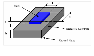
A basic structural model of microstrip patch antenna is shown in Figure 1. The dimensions of the patch are given along with the feed network. The fabricated microstrip patch antenna is also shown as a three-dimensional radiation pattern of the fabricated antenna. [3]
Fig.1. Model of microstrip patch antenna [3]
3 THEORY
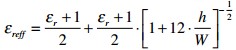
Most of the electric field lines reside in the substrate and parts of some lines in air. As a result, this transmission line cannot support pure transverse-electric-magnetic (TEM) mode of transmission. Hence, an effective dielectric constant (εeff ) must be obtained in order to account for the fringing and the wave propagation in the line. The expression for εeff [4] is given by Balanis as:
(1)
IJSER © 2013 http://www.ijser.org
International Journal of Scientific & Engineering Research, Volume 4, Issue 7, July-2013 2031
ISSN 2229-5518
Where, εreff = Effective dielectric constant
εr = Dielectric constant of substrate h = Height of dielectric substrate
W = Width of the patch
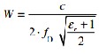
For efficient radiation, the width [5] is given by,
(2)
4 RESULTS AND DISCUSSION
Simulation results are presented by using HFSS Softwer. Fol- lowing the analytical approach presented in section 3, S pa- rameter, Y parameter, Radiation Pattern (2D), Radiation Pat- tern (3D), Radiation Characteristics (RHCP, LHCP) results are evaluated.
In the following table we have summarized the values of different important parameters related to microstrip patch antenna. Here for example parameter ‘dx’ implies the width of patch (mentioned as ‘W’ in equation 1 and 2). Again, it is to be mentioned that substrate height is also denoted as ‘dx’ in the table (mentioned as ‘h’) in equation 1.
TABLE 1
PARAMETERS
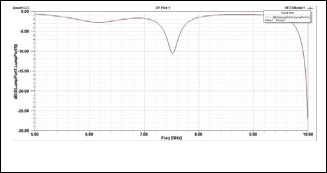
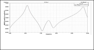
Characteristic curve of S parameter is shown in fig. 2. From the fig, it is evident that the antenna is resonating around 7.5 GHz. More accurate results could be achieved by zooming in the simulation 7.00 GHz and 8.00 GHz.
Fig.2. Characteristic curve of S parameter
Characteristic curve of Y parameter is shown in fig. 3. From the fig, it is evident that there are 3 maxima and 2 mini- ma. Maximum frequency gains are -17dB, -39dB and -20dB respectively and Minimum frequency gains are -53dB and -
49dB respectively.
Fig.3. Characteristic curve of Y parameter
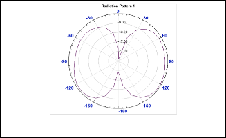
Radiation Pattern (2D) is shown in fig. 4.
Fig.4. Radiation Pattern (2D)
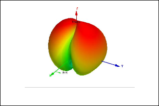
Radiation Pattern (3D) is shown in fig. 5.
From the fig. 4 and fig. 5, it is evident that the input im- pendence of the patch is matched to that of the feed line. This can be achieved by creating a parameterized model of the ge- ometry and search for the feed position which will yield a minimum value of the reflection coefficient. The beamwidth is
100 degree and Front to back ratio is -3 dB.
IJSER © 2013 http://www.ijser.org
International Journal of Scientific & Engineering Research, Volume 4, Issue 7, July-2013 2032
ISSN 2229-5518
is suitable. S Parameter, Y Parameter, Radiation Pattern (2D), Radiation Pattern (3D), Radiation Characteristics (RHCP, LHCP) of the antenna has been successfully investigated. These fundamental parameters are modeled with the equa- tions and estimated with HFSS software and measured the result of the antenna designing.
REFERENCES
Fig.5. Radiation Pattern (3D)
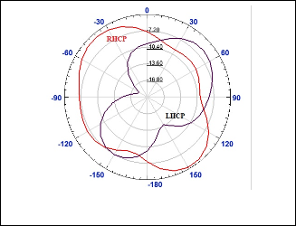
The radiation characteristics (RHCP, LHCP) for Mi- crostrip patch antenna is shown in fig. 7.
[1] David M. Pozar, “Microstrip Antennas”, Proceedings of the IEEE, Vol. 80, No
1, p.p. 79-91, January 1992.
[2] Lizhong Zheng, David N. C. Tse, “Diversity and Multiplexing: A Fundamen- tal Tradeoff in Multiple-Antenna Channelsf”, IEEE Transactions on Infor- mation Theory, Vol. 49, NOo 5, p.p. 1073-1096, MAY 2003
[3] K.Meena alias Jeyanthi, A.P.Kabilan, “Modeling and simulation of Microstrip patch array for smart antennas”, International Journal of Engineering, vol. 3, No. 6 pp. 62-70, December 2010
[4] Isha Puri, Archana Agrawal, “Bandwidth and Gain Increment of Microstrip
Patch Antenna With Shifted Elliptical Slot”, International Journal of Engineer-
ing Science and Technology, Vol. 3 No. 7, pp.5539-5545 July 2011
[5] Md. MahabubAlam, RifatAhmmedAoni, Md. Toufikul Islam, “Gain Im-
provement of Micro Strip Antenna Using Dual Patch Array Micro Strip An- tenna”, Journal of Emerging Trends in Computing and Information Sciences, VOL. 3, NO.12 pp. 1642-1648 December, 2012
Fig.6. Simulated radiation pattern of Microstrip patch anten- na (Brown line: RHCP, Red line: LHCP)
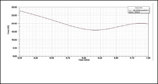
The gain for Microstrip patch antenna is shown in fig. 8. From the fig, it is evident that the gain is 28 dB (at 5 GHz).
Fig.7. Simulated gain for Microstrip patch antenna
4 CONCLUSION
Presented Microstrip Patch Antenna concludes that inset feed
IJSER © 2013 http://www.ijser.org