International Journal of Scientific & Engineering Research, Volume 4, Issue 10, October-2013 1102
ISSN 2229-5518
Performance Evaluation of Biocides and the Role of Efficient Water Injection in Oil Technology
Pankaj Dinesh Javalkar
Abstract— Paper discusses the theoretical aspects of oil technology, giving emphasis to the secondary recovery technique of petroleum i.e. water injection. We discuss the composition of injection water, their treatment by the efficient use of bactericides a. k. a. biocides. We observe the morphology, staining properties and special characteristics of the Sulphur Reducing Bacteria (SRB) and General Aerobic Bacteria (GAB) present in injection water. Paper briefs on the performance efficiency and study the mechanism of action of biocides, briefing on the environmental hazards they can cause if used unwisely. Composition of few media and stains prepared are included in this paper. During course of experiment, individual handling of instruments,
including expertise in microscopy was achieved.
Index Terms — Oil technology, sulphur reducing bacteria, general aerobic bacteria, biocides, water injection.
—————————— ——————————
INTRODUCTION
T
he World today is fuelled by the power of oil. Thereby we can conclude that one of the most significant technologies among several others is Oil Technology. The three im- portant stages for oil, rather petroleum, formation is given by the petroleum trilogy. As per said trilogy the three crucial points considered are source rock, cap rock and reservoir rock. The kerogen- derived gold has to be obtained through a matu- ration process which comprises of three stages: (i) Diagenesis- bacterial activities begin degradation of organic matter aka kerogen. (ii) Catagenesis- thermal degradation and cracking occur at high pressure and temperature. (iii) Metagenesis- Re- sidual C-C links are cracked at much higher temperatures. This fluid created is expelled to reservoir rocks and cap rocks where further development takes place. Three classical steps for oil recovery are distinguished as primary, secondary and
tertiary.
Primary Recovery
Corresponds to natural drive; obtained simply by reduction of the pressure in the reservoir. HC’s are recovered from a field by means of a number of wells, a recovery which depends on reservoir size and characteristics. The initial reservoir pressure is often high enough that when a well is opened, the oil and gas in the reservoir slow freely to the surface; such a well is called eruptive. As the reservoir pressure declines, the drop in pressure between bottom of the well and surface is too low, and the use of a simulation technique called artificial lift be- comes necessary. Artificial lift may involve the installation of a pump in the well. During production, pressure in the entire reservoir drops progressively. The pressure drop created by opening the well influences the displacement of all fluid pre- sent in the reservoir. An oil reservoir can be composed of (i) oil alone, with its dissolved gas (ii) oil and gas in a gas cap (iii) oil alone and water in an aquifer, and gas in a gas cap. Depending on the case several production mechanisms are possible: solu-
————————————————

E-mail: pankaj.dj.2008@gmail.com, +91-9930238624
tion gas drive, gas cap expansion, aquifer drive. Solution gas drive consists of expulsion of light HC components from oil phase to a gas phase. This expulsion is possible when the res- ervoir pressure drops below the bubble point pressure. The light HC’s expelled form bubbles of gas and then a gas phase. Gas cap expansion is expansion of gas present in gas cap be- cause of drops in reservoir pressure. Aquifer drive is the push of aquifer when oil is produced; the aquifer is considered ac- tive when it maintains reservoir pressure. In some cases, the aquifer is inactive, so reservoir pressure drops rapidly. When pressure is so low that production levels are too low when production of water or gas extracted from produced fluid is too high, primary production is no longer possible. Typically only 10% of oil initially in place at the field can be produced by this method of recovery.
Secondary Recovery
. Injection of gas or water into a reservoir is carried out with two objectives: to maintain pressure and to push oil towards producing wells. Water can be injected into aquifer and gas in the gas cap. But very often, fluid injection is distributed over an entire field. Injection creates a zone of fluid around injec- tion well. With subsequent injections, these zones extend until breakthrough occurs at the producer. At breakthrough, the proportion of injected fluid in the produced fluid increases. At this time, not all of the original oil in place has been swept by injected fluid. On average, 15-60% of the oil initially in place in the field can be recovered. The exact percentage of recovery depends on the nature of oil in place, the characteristics of reservoir, and the number and positions of the wells. Wells may be either horizontal or vertical in nature.
Tertiary Recovery
More sophisticated techniques, called improved oil recovery (IOR), can be used. These techniques include enhanced oil recovery (EOR) mechanisms and sophisticated technologies. The objective of EOR is to increase oil production by improv- ing oil flow and sweep in the reservoir. The sophisticated technologies include well amelioration (such as smart wells and completion), amelioration of surface facilities, and optimi- zation of reservoir characterization. All these techniques vary with time and from country to country, whereas EOR mecha- nisms basically remain the same, comprising of four methods-
IJSER © 2013
http://www.ijser.org
thermal, chemical, miscible, microbial[1].
Water Injection
The water injection method is the secondary recovery tech- nique used in oil production is where water is injected back into the reservoir usually to increase pressure and thereby stimulate production. Water injection wells can be found both on- and offshore. This method is used to increase oil recovery from an existing reservoir. Water is injected for two reasons: (i) For pressure support of the reservoir, also known as voidage replacement (ii) To sweep or displace the oil from the reser- voir, and push it towards an oil production well. Normally only 30% of the oil in a reservoir can be extracted, but water injection increases that percentage (known as the recovery factor) and maintains the production rate of a reservoir over a longer period of time[2].
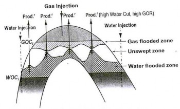
Figure 1 Water and gas injection into aquifer and gas cap
Sulphur Reducing Bacteria And General Aerobic Bac- teria
Sulphate-reducing bacteria (SRB) are anaerobic microorgan-
isms that use sulphate as a terminal electron acceptor in, for example, the degradation of organic compounds. They are ubiquitous in anoxic habitats, where they have an important role in both the sulphur and carbon cycles. SRB can cause a serious problem for industries, such as the offshore oil indus- try, because of the production of sulphide, which is highly reactive, corrosive and toxic. However, these organisms can also be beneficial by removing sulphate and heavy metals from waste streams. There are several explanations for the aggravation of corrosion of iron and steel in oxygen-free con- ditions by sulphate-reducing bacteria. These are (a) stimula- tion of the cathodic part of the corrosion cell by the removal and utilization of the polarizing hydrogen by the bacteria, (b) stimulation of the cathodic reaction by solid ferrous sulphides formed by the reaction of ferrous ions with sulphide ions pro- duced by bacteria, (c) stimulation of the anodic reaction, metal dissolution, by bacterially produced sulphide, (d) local acid cell formation and (e) formation of iron phosphide by reaction of the metal with bacterially reduced phosphates. SRBs are
associated with clogging of pipelines and systems. They are responsible for formation, release and transformation of hy- drocarbons. Capable of contaminating wide areas of sea water within a few decades, they are readily introduced into water systems by drilling procedures. They diminish total yield of petroleum and thereby brings down the economic yield. Slime forming bacteria belongs to the genera Pseudomonas flavobac- terium, E.coli, aerobacter and bacillus. These organisms prolif- erate on the surface, producing dense masses which prevents the penetration of oxygen to the surface. Slime forming bacte- ria are aerobic organisms which develop polysaccharide “slime” on the exterior of their cells. The slime controls per- meation of nutrients to the cells and may breakdown various substances, including biocides. These are heterotrophic, they obtain their energy from organic source such as alcohol, sugar, acids etc. Pseudomonas will utilize hydrocarbon as their ener- gy source. The slime forming bacteria produce a slimy capsule under certain environmental conditions. This capsule is the major component of microbiological slimes found in many water floods. Bacterial cells devoid of capsules are also slimy in nature and can contribute plugging. Large mass of viscous material present on the filters can indicate the presence of GAB. Such masses can causes serious problems like (i) Plug- ging of filters and injection wells, (ii) Formation of concentrat- ed cells. Plugging of a filter and injection wells is often the first indication that GAB are present. Plugging of a formation by bacterial slime is quite serious because slime does not general- ly respond well to remedial treatment, such as acidizing and surfactant treatment. In addition to plugging, slime masses adhering to the sides of line and equipment may cause corro- sion by the formation of concentrated cells. Slime formers are themselves not corrosive, but by shielding the metal surface from oxygen can cause oxygen concentration cells or provide an environment for the growth of the sulphate reducing bacte- ria [3].
BIOCIDES AND MECHANISM OF ACTION
A biocide is a chemical substance capable of killing living or-
ganisms, usually in a selective way. Biocides are commonly used in medicine, agriculture, forestry, and in industry where they prevent the fouling of water and oil pipelines. Some sub- stances used as biocides are also employed as anti-fouling agents or disinfectants under other circumstances: chlorine, for example, is used as a short-life biocide in industrial water treatment but as a disinfectant in swimming pools. Many bio- cides are synthetic, but a class of natural biocides, derived from e.g. bacteria and plants, includes Brassica oleracea, Bras- sica oleracea gemmifera, and Clostridium botulinum bacteria. A biocide can be a pesticide or an antimicrobial. In laboratory tests a maximum tolerable microbial population limit in sys- tems is determined. When these data are known in many cases the number of bacteria and other microrganisms needs serious
reduction. This can be accomplished by addition of biocides; chemical compounds that are toxic to the present microrgan- isms. Biocides are usually slug fed to a system to bring about rapid effective population reductions from which the mi- crorganisms cannot easily recover. There are various different biocides, some of which have a wide range of effect on many different kinds of bacteria. They can be divided up into oxidis- ing agents and non-oxidising agents.
2.1.1 Chlorine
Chlorine is the most widely used industrial biocide today. It has been used for disinfection of domestic water supplies and for the removal of tastes and odours from water for a long time. The amount of chlorine that needs to be added in a water system is determined by several factors, namely chlorine de- mand, contact time, pH and temperature of the water, the vol- ume of water and the amount of chlorine that is lost through aeration. When chlorine gas enters a water supply it will hy- drolyse to form hypochlorous and hydrochlorous acid. The latter determines the biocidal activity. This process takes place according to the following reaction:
Cl2 +H2 O----->HOCl+HCl
UV-light, so that more hydrochlorous acid will originate and the biocidal action will be enhanced.
2.1.4 Hypochlorite
Hypochlorite is salt from hypochlorous acid. It is formulated in several different forms. Usually hypochlorite is applied as sodium hypochlorite (NaOCl) and calcium hypochlorite (Ca(OCl)2). These compounds can be applied as biocides. They function in very much the same way as chlorine, alt- hough they are a bit less effective.
2.2.5 Ozone
Ozone is naturally instable. It can be used as a powerful oxi- dising agent, when it is generated in a reactor. As a biocide it acts in much the same way as chlorine; it disturbs the for- mation of ATP, so that the cell respiration of microrganisms will be made difficult. During oxidation with ozone, bacteria usually die from loss of life-sustaining cytoplasm. While the oxidation process takes place ozone parts into oxy- gen and an ozone atom, which is lost during the reaction with cell fluids of the bacteria:
O ------->O +(O)
3 2
Hydrochlorous acid is responsible for the oxidation reactions
with the cytoplasm of microrganisms, after diffusion through
the cell walls. Chlorine than disturbs the production of ATP (adenosine triphosphate), an essential compound for the respi- ration of microrganisms. The bacteria that are present in the water will die as a consequence of experienced breathing
problems, caused by the activity of the chlorine. The amount of chlorine that needs to be added for the control of bacterial growth is determined by the pH. The higher the pH, the more chlorine is needed to kill the unwanted bacteria in a water system. When the pH values are within a range of 8 to 9, 0.4 ppm of chlorine must be added. When the pH values are within a range of 9 to 10, 0.8 ppm of chlorine must be add- ed.
Chlorinedioxide
Chlorine dioxide is an active oxidising biocide, that is applied more and more due to the fact that is has less damaging effects to the environment and human health than chlorine. It does not form hydrochlorous acids in water; it exists as dissolved chlorine dioxide, a compound that is a more reactive biocide at higher pH ranges. Chlorine dioxide is an explosive gas, and therefore it has to be produced or generated on site, by means of the following reactions:
Cl2 +2NaClO2 ----->2NaCl+2ClO2
or
2 HCl + 3 NaOCl + NaClO2 -> 2 ClO2 + 4 NaCl + H2 O.
Chloroisocyanurates
These are organo-chlorine compounds that will hydrolyse into hypochlorous acid and cyanuric acid in water. The cyanuric acid reduces chlorine loss due to photochemical reactions with
A number of factors determine the amount of ozone required
during oxidation, these are pH, temperature, organics and solvents, and accumulated reaction products. Ozone is more environmentally friendly than chlorine, because it does not add chlorine to the water system. Due to its decomposition to oxygen it will not harm aquatic life. Usually 0.5 ppm of ozone is added to a water system, either on continuous or intermit- tent basis.
Acrolein
Acrolein is an extremely effective biocide that has an envi- ronmental advantage over oxidising biocides, because it can easily be deactivated by sodium sulphite before discharge to a receiving stream. Acrolein has the ability to attack and distort protein groups and enzyme synthesis reactions. It is usually fed to water systems as a gas in amounts of 0.1 to 0.2 ppm in neutral to slightly alkaline water. Acrolein is not used very frequently, as it is extremely flammable and also toxic.
Amines
Amines are effective surfactants that can act as biocides due to their ability to kill microrganisms. They can enhance the bio- cidal effect of chlorinated phenolics when they are applied in water.
Chlorinated phenolics
Chlorinated phenolics, unlike oxidising biocides, have no ef- fect on respiration of microrganisms. However, they do induce growth. The chlorinated phenolics first adsorb to the cell wall
of microrganisms by interaction with hydrogen bonds. After adsorption to the cell wall they will diffuse into the cell where they go into suspension and precipitate proteins. Due to this mechanism the growth of the microrganisms is inhibited.
Copper salts
Copper salts have been used as biocides for a long time, but their use has been limited in recent years due to concerns about heavy metal contamination. They are applied in amounts of 1 to 2 ppm. When the water that is treated is locat- ed in steel tanks copper salts should not be applied, because of their ability to corrode steel. Copper salts should not be used in water that will be applied as drinking water either, because they are toxic to humans.
Organo-sulphur compounds
Organo-sulphur compounds act as biocides by inhibiting cell growth. There are a variety of different organo-sulphur com- pounds that function in different pH ranges. Normally energy is transferred in bacterial cells when iron reacts from Fe3+ to Fe2+. Organo-sulphur compounds remove the Fe3+ by complexion as an iron salt. The transfer of energy through the cells is than stopped and immediate cell death will follow.
Quaternary ammonium salts
Quaternary ammonium salts are surface-active chemicals that consist generally of one nitrogen atom, surrounded by substi- tutes containing eight to twenty-five carbon atoms on four sights of the nitrogen atom. These compounds are generally most effective against bacteria in alkaline pH ranges. They are positively charged and will bond to the negatively charged sites on the bacterial cell wall. These electrostatic bonds will cause the bacteria to die of stresses in the cell wall. They also cause the normal flow of life-sustaining compounds through the cell wall to stop, by declining its permeability. Use of qua- ternary ammonium salts is limited, due to their interaction with oil when this is present and the fact that they can cause foaming.
Because biocides are intended to kill living organisms, many biocidal products pose significant risk to human health and welfare. Great care is required when handling biocides and appropriate protective clothing and equipment should be used. The use of biocides can also have significant adverse effects on the natural environment. Anti-fouling paints, espe- cially those utilizing organic tin compounds such as TBT, have been shown to have severe and long-lasting impacts on ma- rine eco-systems and such materials are now banned in many countries for commercial and recreational vessels (though sometimes still used for naval vessels). Disposal of used or unwanted biocides must be undertaken carefully to avoid se-
rious and potentially long-lasting damage to the environment. Like most production activities, oil and gas production pro- cesses generate large volumes of liquid waste. Oilfield wastewater or produced water contains various organic and inorganic components. Discharging produced water can pol- lute surface and underground water and soil [4].
3 METHODOLOGY
3.1 Collecting Representative Samples From Oil Reser- voirs: A Real Challenge
Collecting representative samples is the first and probably the main difficulty micro biologists face in making a microbiologi- cal study of deep subsurface. In oil reservoirs, indigenous bac- teria are found mainly attached on surfaces in the form of bio- films. The best way to study these microbial populations would thus be to collect representative biofilm samples and transport them safely to the laboratory. Sophisticated equip- ments have been designed to recover cores while maintaining original in situ conditions and protecting them from contami- nation. Tracers have also been used in the drilling fluids to evacuate the risk of exogenous contamination of the samples. Use of these rigorous and efficient techniques represents huge constraints in terms of equipment, personnel requirements, budget and scheduling of the field campaign. Thus these techniques have never been implemented for microbiological investigation of oil field. To prevent contamination, sections of fresh cores were wiped with 70% ethanol and immediately placed under anaerobic conditions. The pressures was sup- posed to force fluids and gases outward, thus preventing the entry of contaminants into the interior of the cores. Center- most part of each section of the core was used for microbiolog- ical investigations. Bacteria were grown in low numbers from all core samples studied, suggesting the existence of indige- nous bacterial communities in the oil bearing strata. Reservoir depth ranged from 1067 to 4575 meters, with in situ tempera- ture of up to 1500 C. Core samples were delivered to the labor- atory in sterile anaerobic jars, sealed to prevent exposure to air and surface contamination. Small rock chips of 1 cm3 size from the whole core center where inoculated in- culture medium and incubated at 30, 60 and 900C. Different bacterial cultures were grown at each temperature. Samples of fluids produced from the reservoir are collected from topside facilities and ana- lyzed. Precautions must be taken to prevent contamination. This includes (i) use of sterile bottles preconditioned with an anoxic (inert) atmosphere, (ii) sterilization of fittings and tub- ings prior to use, (iii) careful removal of any stagnant liquid from the sampling line before sampling. Another source of introduction of exogenous bacterial populations into an oil reservoir is water flooding, whatever the source of injection water, including production water reinjection. Reservoirs that have not been injected should thus preferably be selected for the microbiological investigation of truly indigenous microflo- ra. Currently there is no absolutely reliable way to collect res- ervoir microbiological samples that can be considered une- quivocally native to the formation of interest [5], [6].
Preparation Of Growth Media
Composition of growth media is tabulated for SAB and GAB.
Sodium lactate (50-70%) | 4.0 ml |
Yeast Extract | 1.0 g |
Ascorbic acid | 0.1 g |
MgSO4 .7H2 O | 0.2 g |
K2 HPO4 | 25.0 g |
Fe(SO4 )2 (NH4 )2 .6H2 O | 0.2 g |
NaCl | 25.0 g |
Distilled Water | 1000 ml |
pH is maintained by use of NaOH solution. | 7.3 |
Table 1 Composition for SAB
Dextrose | 1.0 g |
Beef Extract | 3.0 g |
Peptone | 5.0 g |
NaCl | 25.0 g |
Distilled Water | 1000 ml |
pH is maintained | 7 |
Table 2 Composition for GAB
Preparation Of Gram Stains
Solution
1% Crystal Violet
1 g crystal violet (CI 42555) dissolved in 100 mL distilled water
Solution expires approximately 1 year from the date of prepa- ration.
1% Basic Fuchsin
1 g basic fuchsin (CI 42500) dissolved in 100 mL distilled wa- ter. This dye is also known as pararosanalin. Solution expires approximately 1 year from date of preparation
Gram's Iodine Solution
1 g iodine, 2 g potassium iodide dissolved in 300 mL distilled
water. Expiry date unknown.
Gallego's Differentiating Solution
Concentrated formaldehyde (37 - 40%), 2 mL glacial acetic acid (concentrated), 1 mL 100 mL distilled water. Mix the above well. Solution expires approx. 6 months from prepara- tion date.
Picric acid acetone
1 g picric acid in 100 mL pure acetone. Store in an airtight con- tainer. Expiry unknown.
Procedure
Wash the slide with chromic acid, dry it and smear it with
inoculums in the laminar air flow. Flood slide with 1% crystal violet solution and let it stay for 1 minute (place slides face up on a staining rack).
Rinse with distilled water.
Stain slide with Gram's iodine solution and let it stay for 1 minute. Rinse with distilled water.
Decolorize by use of pure acetone until background is clear. Immediately rinse with distilled water.
Flood the slide with 1% basic fuchsin and allow it to stand
for 2 minutes.
Rinse with distilled water. Allow it to dry and then observe
under microscope to study the morphology of bacteria detect- ed.
EXPERIMENTATION
Membrane filtration
Injection water given is filtered by use of membrane filter (0.45 micrometer). Sterilization of membrane filter, composed of cellulose acetate/ nitrate, is done by γ- radiation. Equipment used for filtration is autoclaved. This process requires a vacu- um to be applied downstream, enabling filtration to take place rapidly. Substances which cannot be sterilized by method of autoclaving can be done by this technique.
Test performance For Analysis Of Biocides
Four samples of biocides were tested provided by microbiolo- gy department of RGL, ONGC, Panvel. Samples are named as A, B, C and D. These samples were sent for testing in laborato- ry as part of tender.
Physical State
Sample bottle should be shaken thoroughly and taken in a
clean cuvette. Turbidity is evaluated using Nephelo Turbidity
meter. Turbidity of sample should not be within limits set by

user at 24+ 20C.
Miscibility
Injection water is filtered through a membrane filter (0.45 mi-
crometer). Solution of bactericide sample is prepared in fil-
tered injection water (1% w/v). Bactericide solution should be
clear when observed visually.
Compatibility
Bactericide solution prepared in filtered injection water is tak-
en in graduated cylinder of100 ml capacity. To 100 ppm of bac-
tericide we add 5ppm i.e. 0.5 ml of polyelectrolyte (flocculant),
10 ppm i.e. 1 ml of oxygen scavenger, 10 ppm of corrosion in-
hibitor and total volume is made to 100 ml with filtered injec-
tion water. Turbidity of this solution is then measured, which
should be less than 1 NTU at ambient temperature.
Stability Test
Bactericide sample (10 ml) is taken in a graduated cylinder of
50 ml capacity. Cylinder is stoppered and sealed, sealed and
kept for one hour in water bath maintained at 90+50C. It is then
removed from bath and cooled to room temperature. After
shaking cylinder thoroughly, no precipitate or turbidity
should be visible at room temperature.
Functional Group Test
Nitrous Acid Test For Amine Group
Take few drops of sample in 2 ml of 2M HCl. Mix well and
cool in ice bath. Add 4-5 drops of cold 20% aqueous solution
of sodium nitrate. If colourless nitrogen gas bubbles are
evolved, it indicates presence of primary aliphatic amine. Gas evolved should not be brown nitrogen oxide; this indicates absence of amine group. If no evolution of gas occurs, look for formation of yellow to orange liquid or solid; this indicates presence of secondary amine or tertiary aromatic amine. Ter- tiary aliphatic amines do not react at this temperature. If no reaction as above occurs, warm half of the solution to room temperature; evolution of colourless gas at higher tempera- tures indicates primary aromatic amine. To remaining half, add drop by drop ice cold solution of about 50 mg of β- Naphthol in 2 ml of 2M NaOH. Formation of orange to red azo dye further indicates primary aromatic amine.
Tollens Test For Aldehyde Group
Take 2 ml of AgNO3 , one drop of 3M NaOH and 2M aqueous
NH3 drop by drop in a test tube. Shake while adding, until
precipitates of silver oxide just dissolves. Add one drop bio-
cide sample to this solution, shake well and let it stand for ten
minutes. If no reaction occurs heat it to 350C in water bath for
5 minutes. Formation of silver mirror on inside of test tube
indicates presence of aldehyde group.
Microbiological Analysis Of Injection Water By Serial Dilution Technique
Sample 1: Cooling tower water collected at 9:45 AM on 17-06- 13
Sample 2: Raw water collected at 9:55 AM on 17-06-13 Microbial count of aerobic and anaerobic bacteria was carried out. Samples for GAB were kept in BOD incubator for 4 days where as samples for SRB were kept in anaerobic workstation in serum bottle for 28 days.
RESULTS AND DISCUSSION
Biocides Samples
The fuctional group of any biocide determines the overall effi- ciency and its physical and chemical properties. As these bio- cide samples were to be used in oil wells where water from the ocean is to be used for water injection they are subjected to dissolve in water. Even the stability after dissolution affects the working and overall efficiency of the water injection tech- nology. Sample A and B tested positive for amine. Sample C and D tested negative for amine. Sample A tested positive for aldehyde where as sample B tested negative for aldehyde. All the samples were miscible and compatible with water. Stabil- ity tests showed that all biocides were stable.
Serial Dilution Test
Sample 1 and sample 2 for injection water showed the pres- ence of GAB upto 10-8 dilutions after incubation in BOD incu- bator for 4 days. SRB was found in samples after incubation of 28 days in anaerobic chamber.
Microscopic Observations
Samples 1 and 2 were observed under the the microscope and the observations were tabulated. Each sample were oservered carefully and characterized. Their morphology and features are described.
Table 3 Results for GAB
STAINING | SAMPLE NO. | MORPHOLOGY AND FEATURE |
STAINED SAM- PLE | SAMPLE 1
SAMPLE 2 | Cocci, Darkly stained (pink), less number of streptobacilli. Long chains of Strep- tococci, Darkly stained (pink), less number of bacilli |
UNSTAINED SAMPLE | SAMPLE 1
SAMPLE 2 | Motile forms, scat- tered in the media, cocci. Streptococci, non- motile. |
Table 4 Results for SRB
STAINING | SAMPLE NO. | MORPHOLOGY AND FEATURE |
STAINED SAM- PLE | SAMPLE 1 | Coccobacilli, stained pink in colour. |
UNSTAINED SAMPLE | SAMPLE 1 | Motile, cocci. |
CONCLUSION
In our study of the injection water used in oil technology, we detected the presence of SRBs and GABs in the samples col- lected on 17th of June, 2009; Sample 1 being cooling water at 9:45 AM and Sample 2 being raw water at 9:55 AM. Their morphologies and identifying features are found to be distinct when studied by use of microscopy. Motile bacteria, strepto bacilli, strepto cocci, staphylococci etc. were identified when the samples were subjected to staining and observed under a microscope. We also studied their differentiating features.
ACKNOWLEDGMENT
The authors wish to thank Mr. Manjeet Singh; Chief Chemist, RGL, ONGC, Mumbai, who has kindly agreed to be our men- tor for this project work.
.
REFERENCES
[1] http://en.wikipedia.org/wiki/Enhanced_oil_recovery, 27-05-2013,
18:52.
[2] Bernard Olliver and Michel Magot, Petroleum Microbiology, pp.50- 200 Amer Society for Microbiology; 1 edition (June 2005)
[3] John Raymond, Postgate, FRS., The Sulphate Reducing Bacteria,
Cambridge University Press; 1 edition (November 30, 1979), pp. 124-150.
[4] James W. McCoy, Microbiology of Cooling Water, Chemical publish- ing co., pp. 4-60.
[5] Ahmadun Fakhru’l-Razi et.al, Review of technologies for oil and gas produced water treatment, Journal of Hazardous Materials, Volume 170, Issues 2–3, 30 October 2009, Pages 530–551.
[6] J L Lynch and R G J Edyyyean, Biofouling in oilfield water systems-A review, Biofouling, Volume 1, Issue 2, 1988, pp. 147-162