International Journal of Scientific & Engineering Research, Volume 4, Issue 8, August-2013 1719
ISSN 2229-5518
Performance Enhancement of Power System Using 48 Pulse SSSC in the Presence of SMIBS and 14 Bus System
M.Kavitha*,K.Madhavi**,V.Thenmozhi**,D.Kalavathi**,A.Ragavendiran*
Abstract-In the last decade, commercial availability of Gate Turn-Off (GTO) thyristor switching devices with high power handling capability and the advancement of the other types of power semiconductor devices such as insulator gate bipolar junction transistor (IGBT’s) have led to the development of fast controllable reactive power sources utilizing new electronic switching and converter technology. These switching technologies additionally offer considerable advantages over existing methods in terms of space reductions and fast effective damping. The increasing method for power transmission capability by compensating the voltage drop in the long line with series capacitor was proposed in the early days of AC power transmission. However, its application for the actual system has been restricted due to the transient stability and the low frequency oscillation. In this work, it is proposed to develop Static Synchronous Series Compensator (SSSC) using 48-pulse voltage source converter to improve the power quality of the system. 48-pulse SSSC is the combination of four twelve pulse connected in cascaded manner. In a power system it improves power flow and also regulates the Bus voltage in the transmission line. SSSC using 48- pulse converters does not need an additional coupling transformer. The lowest order harmonic present in the output voltage will be 47th harmonic.48-pulse SSSC are to be modelled in the simulink environment. The basic characteristics of 48 pulse SSSC have to be analyzed on the practical utility system. The model has to be simulated with Matlab software to demonstrate system behaviour of SSSC. Numerical results have to be demonstrated on the practical Bus system with the SSSC model. It has to be validated that there is a possibility of regulating active power flow, reactive power flow and minimizing the power losses simultaneously with proposed SSSC parameter.
Index Terms– GTO,IGBT,SSSC,FACTS,VSC,VSI,TSC,TCR,SMIBS,SVG,PQ,PV .
—————————— ——————————
1 INTRODUCTION
Power transfer capability of long transmission lines is limited by stability considerations. Reducing the effective reactance of lines by series compensations is a direct approach to increase transmission capability [1].
The commercial availability of Gate Turn-Off (GTO) thyristor switching devices with high power handling capability and development of power semiconductor devices as IGBT’s have controlled the power flow utilizing new electronic switching and converter technology.

*Assistant professor/ Dept.of Electrical & Electronics Engineering
**B.Tech Students/ Dept. of EEE / Dr.S.J.S Paul Memorial College of
Engineering & Technology / Pondicherry / India
Flexible alternating current transmission systems (FACTS) devices are usually used for dynamic control of parameters such as voltage, impedance and phase angle of high voltage AC lines. Static Synchronous Series Compensator (SSSC) with 48 pulse Voltage Source Converter (VSC) is considered in this paper to control the reactive power flow in the interconnected system. SSSC has enormous advantages over other FACTS devices. It injects voltage in series by eliminating bulky passive components such as capacitor and reactors. SSSC reduces the equivalent line impedance and enhances the active power. The DC inner Bus of SSSC allows in incorporating a substantial amount of energy storage. SSSC has no source or sink of power attached to its terminals, further it neglects the power losses of the converter. The use of Voltage Source Inverter (VSI) has
been widely accepted as the next generation of flexible
IJSER © 2013 http://www.ijser.org
International Journal of Scientific & Engineering Research, Volume 4, Issue 8, August-2013 1720
ISSN 2229-5518
reactive power compensation to replace other conventional
VAR compensation such as Thyristor-Switched capacitor (TSC) and Thyristor controlled reactor (TCR). This paper deals with a cascaded multilevel converter model, which is a 48-pulse (three levels) source converter. The voltage source converter described in this paper is a harmonic neutralizer and improves the performance of the power system [2]. The power system is analyzed in the presence of Single Machine Infinite Bus System (SMIBS) as well as 14 bus system with 48 pulse SSSC.
2 STATIC SYNCHRONOUS SERIES COMPENSATOR (SSSC)
The voltage-source converter-based series compensator, called Static Synchronous Series Compensator (SSSC), was proposed by Gyugyi in 1989 to use the converter-based technology uniformly for shunt and series compensation, as well as for transmission angle control.
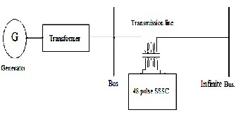
Fig.1:Block diagram of SMIBS with SSSC
It is power electronic based synchronous voltage generator (SVG) that generates almost three phase sinusoidal ac voltages, from a dc source / capacitor bank with voltage in quadrature with reference line current. The block diagram of SSSC in the single machine infinite bus system is shown in the Fig.1.
The basic operating principles of the SSSC can be
explained with reference to the conventional series
voltage across the series capacitor. It forces the opposite
polarity voltage across the series line reactance to increase by increasing the magnitude of the capacitor voltage. The series capacitive compensation works by increasing the voltage across the impedance of the given physical line, which in turn increases the corresponding line current and the transmitted power. It may be convenient to consider series capacitive compensation as a means of reducing the line impedance, in reality. It is really a means of increasing the voltage across the given impedance of the physical line. The SSSC has the inherent ability to interface with an external power supply to provide compensation for the line resistance by the injection of real power, as well as for the line reactance by the injection of reactive power, for the purpose of keeping the effective X/R ratio high. The variable impedance type series compensators cannot exchange real power (except for circuit losses) with the transmission line and can only provide reactive
compensation.
2.1 SSSC Model
The test system is a simple power system 500 kV network grid equipped with the SSSC and its novel controller, which connected in series with the transmission system. Modelling the SSSC compensator, including the power network and its controller in MATLAB / Simulink environment. An 8500 Mvar SSSC device is connected to the 500 kV grid network as shown in Fig.2.
capacitive compensation with the line current and the
IJSER © 2013 http://www.ijser.org
International Journal of Scientific & Engineering Research, Volume 4, Issue 8, August-2013 1721
ISSN 2229-5518
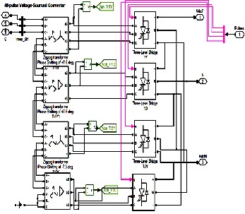
diagram of the 48 pulse VSI. Here, ideal switch and zigzag phase shifting transformers are used to build a GTO type voltage source inverter. The inverter described is harmonic neutralized. It consists of four 3-phase, 3 level inverters and four phase- shifting transformer. The DC bus is connected to the four 3-phase.
Fig.2:Transmission line with SSSC
It shows the SSSC model used in the proposed simulation studies. SSSC considered in this paper is modeled with 48 pulse voltage source inverter, injects a voltage in series with the transmission line through the coupling transformer . SSSC is connected at the midpoint of transmission line. The
reactance compensation capability of SSSC can be made in
one of two ways. One way is to inject a reactance compensating voltage in series with the line whose magnitude is controlled independent of the line current magnitude. In this mode of operation the device is not intended to replicate a specific ohmic value of reactance. The other way to inject a compensating voltage whose magnitude is controlled to be proportional to the line current magnitude.
In this mode the device emulates an ohmic compensating reactance,with the emulated compensating reactance being the constant of proportionality. The control strategy plays a vital rule in design the internal control parts of any FACTS controller .
3 CONSTRUCTION OF 48 PULSE VOLTAGE
SOURCE INVERTER (VSI)
A 48- pulse voltage source inverter is used for the proposed work. With 48 pulse VSI, AC filter are not required. It acts as a harmonic neutralizer. Fig.3 shows the connection
Fig .3: 48-Pulse GTO’s Voltage Source Converter
The four voltage generated by the inverters are applied to secondary windings of four zigzag phase-shifting transformers connected in wye(Y) or Delta(D). The four transformers primary windings are connected in series and the converter pulse patterns are phase shifted so that the four voltage fundamental components sum in phase on the primary side.
The phase shifts produced by the secondary delta connections (-30 degrees) and by the primary zigzag connections(+7.5 degrees for transformers 1Y and 1D, and -
7.5 degrees for transformers 2Y and 2D) allow neutralizing
harmonics up to 45th harmonic.
The voltage Vbc48 and Vca48 exhibit a similar pattern
except phase shifted by 120• and 240• respectively.
IJSER © 2013 http://www.ijser.org
International Journal of Scientific & Engineering Research, Volume 4, Issue 8, August-2013 1722
ISSN 2229-5518
Similarly, the phase voltages Vbn48 and Vcn48 are also
phase shifted by 120• and 240• respectively [3-5].
4 CONTROLLER DESIGN
PID controllers are probably the most commonly used controller structure in industry. They however, face challenges in the aspect of tuning of the gains required for stability and good transient performance. There are several prescriptive rules used in PID tuning. Hence in this paper PI controller is used. The structure of SSSC controller, to modulate the SSSC injected voltage Vq, is shown in Fig.4.
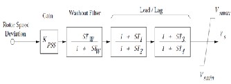
Fig.4:Structure of SSSC based controller
The input signal of the proposed controller is step signal and the output signal is the injected voltage Vq. The structure consists of a signal washout block and two stage phase compensation block. The signal washout block serves as high pass filter, with the time constant TW, high enough to allow signals associated with oscillations in input signal to pass unchanged. The value of TW may be in the range of
1 to 20 seconds. The phase compensation block (time constants T1,T2 and T3,T4) provides the appropriate phase- lead characteristics to compensate for the phase lag between input and the output signals.
In the Fig.4. Vqref repesents the reference injected
voltage as desired by the steady state power flow loop acts quite slowly in practice and hence, in the present study Vqref is assumed to be constant during large disturbance transient period. The desired value of compensation is obtained according to the change in the SSSC injected
voltage Vq which is added to Vqref. The value of T2 =T4
=0.3 as the constnt value[6].
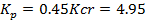
On reducing the blocks in Fig.4 resulted in an oscillatory wave form . Hence Ziegler-Nichols tuning second method is used in this paper for designing the PI controller. Applying Ziegler-Nichols second method we obtain the closed loop transfer function of the System as in equation (1),

The value of kp that makes the system marginally stable so that sustained oscillation occurs can be obtained by the use of Routh’s stability criterion. The Characteristics equation (2) for the close loop system is

The Kp, Ti and Tp values can be determined using the following formulae as shown in Table 1 and they are shown in equation 3.
TABLE 1
 (3)
(3)


5 BUSES
IJSER © 2013 http://www.ijser.org
International Journal of Scientific & Engineering Research, Volume 4, Issue 8, August-2013 1723
ISSN 2229-5518
In the network of a power system the buses becomes nodes
and so a voltage can be specified for each bus. Therefore each bus in a power system is associated with four quantities and they are real power, reactive power, magnitude of voltage and phase angle of voltage. The buses of a power system can be classified into following three types based on the quantities being specified for the buses. The Table 2 shows the quantities specified and to be obtained for each type of bus.
1. Load bus (or) PQ bus
2. Generator bus (or) voltage controlled bus or PV bus
3. Slack bus (or) swing bus or reference bus
TABLE 2
PARAMETERS OF DIFFERENT BUSES
Bus Type | | Quantities Specified | Quantities to be obtained |
Load Bus | P,Q | | |V|, δ |
Generator Bus | P, |V| | Q, δ |
Slack Bus | |V|,δ | P,Q |
5.1 Load Bus
The bus is called load bus, when real and reactive components of power are specified for the bus. The load flow equations can be solved to find the magnitude and phase of bus voltage. In a load bus the voltage is allowed to vary within permissible limits, for example ± 5%.
5.2 Generator Bus
The bus is called generator bus, when real power and magnitude of bus voltage are specified for the bus. The load flow equation can be solved to find the reactive power and phase of bus voltage. Usually for generator buses reactive power limits will be specified.
5.3 Slack Bus
The bus is called slack bus if the magnitude and phase of
bus voltage are specified for the bus. The slack bus is the reference bus for load flow solution and usually one of the generator bus is selected as the slack bus.

Fig.5: Single line diagram of 14-bus network
The single line diagram of 14-bus network is shown in the Fig.5.The stability problem of a power system deals the transmission of the power from one group of synchronous machines to another. During disturbances, the machines of each group swing more or less together, that is they retain approximately their relative angular position. For purposes of analysis machines of each group can be replaced by one equivalent machine. This system has 5 generation units, bus
1 is a slack bus. Also it has 16 transmission lines and 11
load buses. In this system generation units are standard PV buses and loads are represented as constant PQ loads. The P and Q load powers are not voltage dependent and assumed to change as in equation (4),
PL = P L0 (1+ λ)
QL =QL0 (1+λ) (4)
Where,
PL0 – Active base loads QL0 – Reactive base loads PL – Active loads at bus L
IJSER © 2013 http://www.ijser.org
International Journal of Scientific & Engineering Research, Volume 4, Issue 8, August-2013 1724
ISSN 2229-5518
QL –Reactive loads at bus L for the current operating point
as defined by λ [7].
6 SIMULATION RESULTS AND DISCUSSIONS
The closed loop simulation model of SMIBS is shown in
Fig.6. It consists of programmable voltage source, transformer, buses and load. Infinite bus is a bus whose voltage remains constant and cannot be altered by any changes in generator excitation. Since the generator is connected to an infinite bus its terminal voltage remains constant and cannot change.
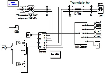
Fig.6: Closed Loop Simulation model of SMIBS
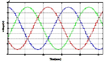
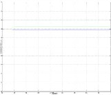
The PI control for 48 pulse inverter based SSSC are Simulated using MATLAB/Simulink to analyze its operation. The various transient disturbances due to faults and step change variation in power are created to the study the performance of PI control for SSSC. The VSI output
voltage is shown in Fig.7.
Fig.7: 48-Pulse VSI Output Voltage
The output waveform of SSSC transfer function with PI
controller is shown in Table 3.
Table 3
WITHOUT PI CONTROLLER | WITH PI CONTROLLER |
| 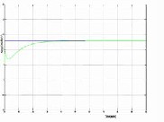
|
The real and reactive power with SSSC is high when compared to the system without SSSC in SMIBS as shown in Table 4. In case of with SSSC the real power is 35.7MW and in case of without SSSC the real power is 18.5MW.
IJSER © 2013 http://www.ijser.org
TABLE 4
International Journal of Scientific & Engineering Research, Volume 4, Issue 8, August-2013 1725
ISSN 2229-5518
WITHOUT SSSC IN SMIBS | WITH SSSC IN SMIBS |
| 
|
The level of real power is increased when SSSC is used to the SMIBS when compared to the open loop operation of the SMIBS. The comparison is shown in Table 5.
TABLE 5
REAL AND REACTIVE POWER WITH AND WITHOUT SSSC
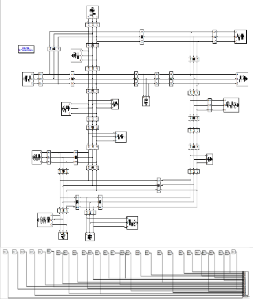
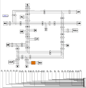
Fig.8:14 Bus system without SSSC
The simulation model of 14 bus system without SSSC is shown in the Fig.8.The corresponding values at each bus is plotted in the Table 6 and Table 7. The simulation model of
14 bus system with SSSC is shown in Fig.9.
TABLE 6
PQ VALUE AT VARIOUS BUS WITHOUT SSSC
IJSER © 2013 http://www.ijser.org
International Journal of Scientific & Engineering Research, Volume 4, Issue 8, August-2013 1726
ISSN 2229-5518
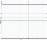
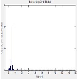
TABLE 8
THD OF SMIBS AND 14 BUS SYSTEM
THD IN SMIBS | THD IN 14 BUS SYSTEM |
| 
|
7 CONCLUSION
The SSSC provides simultaneous or individual control of
Fig.9:14 Bus system with SSSC
TABLE 7
PQ VALUE AT VARIOUS BUS WITH SSSC
BUS | P(MW) | Q(MVar) |
1 | 120.5 | -10.73 |
2 | -230.0 | 20.61 |
3 | -184.6 | 10.68 |
4 | -203.8 | 16.48 |
5 | -176.0 | -25.06 |
6 | -145.2 | -25.33 |
7 | -142.2 | 17.1 |
8 | 30.4 | -2.669 |
9 | -146.4 | 20.36 |
10 | -51.2 | 11.1 |
11 | -25.93 | -2.566 |
12 | -4.054 | 0.0080 |
13 | -7.933 | 0.0020 |
14 | -13.19 | -7.558 |
THD of SMIBS is 3.53% and THD 14 bus system is
1.94%.THD of both the cases are shown in Table 8.
basic system parameters like transmission voltage, real and reactive power. In this paper the performance of power system is analyzed in the presence of both SMIBS and 14 bus system. The reactive power is reduced in case of 14 bus system when compared to SMIBS. The THD of 14 bus system is decreased when compared to SMIBS. It can be concluded that after the incorporation of SSSC the power flow between the lines has been improved and the lower order harmonics has been reduced.
7.1 Scope of Future Work
We can also implement this system with Fuzzy logic.
The number of buses can be increased. As the number of buses increases further it reduce the reactive power, increases the stability and reduces the harmonics.
Number of pulses used in this system can also be increased.
IJSER © 2013 http://www.ijser.org
International Journal of Scientific & Engineering Research, Volume 4, Issue 8, August-2013 1727
ISSN 2229-5518
8 REFERENCES
1.Anju Meghwant and Kulkarni.A.M, “Development of a Laboratory Model of SSSC using RTAI on Linux Platform”, S¯adhan¯a ,Vol.33,Part 5,pp.643-661,(2008).
2.EI-Moursi.M.S. and Sharaf.A.M, “Novel Controller for the
48 Pulse VSC STATCOM and SSSC for Voltage Regulation and Reactive Power Compensation”, IEEE Transaction on Power Systems, Vol. 20, No. 4, pp. 1985-1997, (2005).
3.Matos.S.R and Basilio.J.c., “Design of PI and PID Controllers With Transient Performance Specification”, IEEE Transactions on Education, Vol. 45, No .4, pp. 364
– 370, (2002).
4.Ravi Balam, Kotyada.Kalyani, Shankar Prasad.B, “Dynamic Performance of 48 – Pulse STATCOM,SSSC and UPFC Controller”, International Journal of Engineering Research and Applications(IJERA), Vol. 2, Issue 1, pp. 156 –
163, (2012).
5.Suresh Matur, Jayachandra Shenoy.U, “Impact of STATCOM and SSSC based Compensation on Transmission Line Protection”,16th National Power System conference, (2010) .
6.Sidhartha Padhy.N.P and Padhy.N.P, “A PSO- based
SSSC Controller for Improvement of Transient Stability Performance”, International Journal of Electrical and Computer Engineering, (2007).
7.Satyavir Singh,“Power Tracing in a Deregulated Power System: IEEE 14 Bus case”,International Journal of Computer Technology and App.,Vol.3(3),PP-887 -894, May-
June 2012.
IJSER © 2013 http://www.ijser.org