International Journal of Scientific & Engineering Research, Volume 4, Issue 4, April-2013 514
ISSN 2229-5518
Performance Enhancement of Ez-Source Inverter
Using Induction Motor
N.Gurusakthi, R.Sivaprasad
—————————— ——————————
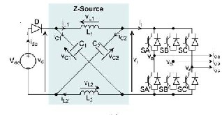
The first proposed Z-Source inverter [1] was in the form of the design as shown in Fig 1.It was viewed as a class of single stage converter also performs buck-boost energy conversion using the LC impedance network. To date, various Z-source topological options have since been developed with either voltage- or current-type conversion ability [1], [2].Among them, the voltage-type inverters are more popular which are tested for applications in motor drives [3]–[6] and fuel cell- [6]– [9] and photovoltaic (PV)- [9]–[11] powered systems, where the dc voltages generated by the sources are constantly varying, determined solely by the prevailing atmospheric conditions (e.g., intensity of solar irradiation).
Although traditional voltage-source inverters (VSIs) can also be used for such applications, their sole voltage step-down operation forces them to operate at a relatively low modulation depth and, hence, poor harmonic performance in most cases. The reason for using a low nominal operating ratio is because their upper modulation range must be reserved for riding through any surge in energy demand. On the other hand, Z- source inverters can be designed with their maximum modulation ratio set to the prevailing nominal case. Any surge in energy demand is then managed by varying the inverter shoot-through time duration, which in effect is a third state introduced for gaining voltage boosting in Z-source inverters, in addition to their voltage-buck operation inherited from traditional VSI.
For controlling the Z-source inverters, many pulse width modulation schemes [12], [13] have also been reported with some achieving a lower switching loss and others realizing an optimized harmonic performance. The added states influence the produced voltage gain. Hence, it's harder to control. For reducing load influence, proper parametric tuning must be done in order to reduce the high-frequency current ripple within the circuit.
Fig 1.Z-Source Inverter
Though parametric tuning is effective in stabilizing gain, it cannot remove the chopping current flowing in to the DC source and can affect the source characteristics. It is due to the high frequency operation of the input diode 'D' shown in fig. 1 during voltage boost operation that can be filtered by placing a second-order LC filter before 'D' which in turn increase the overall cost of the system and produce unwanted dynamic and resonant complexities to the systems.
The above literatures does not deal with solar model controlled by EZ-Source Inverter Hence, instead of using an external LC filter, this paper proposes an embedded Z-Source inverter where the input DC sources is embedded within the LC impedance network, using inverter and capacitive elements for voltage filtering in current-type EZ-Source inverter. Despite these changes, the voltage or current gain of the system is constant. This EZ-Source inverter can be used where source filtering is difficult.
The proposed EZ-source inverters are therefore competitive alternatives that can be used for cases where implicit source filtering is critical. The concepts have been tested extensively in the laboratory using experimentally constructed two- and three-level neutral-point-clamped (NPC) inverters
IJSER © 2013 http://www.ijser.org
International Journal of Scientific & Engineering Research, Volume 4, Issue 4, April-2013 515
ISSN 2229-5518
The two-level voltage-type Z-source inverter is shown in Fig. 1, where an X-shaped LC impedance network is connected between the input dc source and three-phase inverter bridge. With the impedance network added, any two switches from the same phase-leg can now be turned on safely to introduce a shoot-through or short-circuit state with no surge in current observed, since all current paths in the dc front-end are effectively limited by at least an inductive element (L1, L2, or both).
In response to the inserted shoot-through state, the Z-source inverter can then be proven to exhibit voltage-boosting capability, whose corresponding gain expression is derived by considering the inverter-state equations during shoot-through and non shoot-through states, expressed by (1)–(4) with a balanced network assumed (L1 = L2 = L and C1 = C2 = C). Note that for the case of non shoot-through state, it can represent any of the six traditional active states (ii _= 0) or the remaining
two null states (ii = 0), solely determined by the modulation
process.
(Sx = Sx1 = ON, x = A, B, or C; D = OFF)
vL =VC; vi = 0; vd = 2VC; vD = Vdc − 2VC---- (1)
iL = − Ic; ii = iL − iC; idc = 0---- (2)
Non shoot-Through:
(Sx ≠Sx1, x = A, B, or C; D = ON)
vL =Vdc − VC ;vi = 2VC – Vdc; vd = Vdc; vD = 0 ---(3)
idc =iL + iC; ii = iL – iC; idc ≠ 0--- (4)
Performing state-space averaging on (1) and (3) then results in the following expressions derived for the capacitive voltage VC, peak dc-link voltage ˆvi, and peak ac output voltage vx (the latter two happen during the non shoot-through state)
VC =(1 − T0/T)/(1 − 2T0/T ) *Vdc
ˆvi = Vdc / (1 − 2T0/T)= BVdc
vx =M vi/2= B(M Vdc/2)-----(5)
where T0/T refers to the shoot-through ratio (T0/T < 0.5) per switching period, M represents the modulation index used for traditional inverter control, and B = 1/(1 − 2T0/T ) is the boost
factor. Clearly, the term enclosed by the parentheses in the expression for ˆvx represents the output amplitude produced by a traditional VSI, which can be boosted by raising B above unity and adjusting M accordingly. In addition to (5), other expressions governing the voltage-type Z-source inverter
operation can be written as
Diode Blocking Voltage vD = −Vdc/(1 − 2T0/T )-----(6) Inductor Voltage
vL = Vdc (1−T0/T)/ (1−2T0/T) , during shoot-through
vL = −Vdc (T0/T) /(1−2T0/T) , during non shoot-through--- (7)
The proposed Embedded EZ-Source Inverter shown in fig. 1,it has DC sources embedded within the X-shaped LC impedance network with its inductive elements L1 and L2 used for filtering the currents in voltage type EZ-source inverters and its capacitive elements C1 and C2 for voltage filtering in current-type EZ-source inverters . Irrespective of these modifications, the voltage or current gain of the inverter is kept constant. The overall operation is given in Fig 2 as block diagram representation
Fig.2.Block Diagram
The proposed EZ source inverters are hence an alternative that can be utilized where source filtering is significant. However the disadvantage shown in fig .l is that two DC sources of V dc/2 instead of single DC source are required for EZ-Source Inverter. Though this requirement results in higher cost it is not viewed as major issue for PV or even fuel cell applications. This technique has been implemented using Matlab Simulink.
IJSER © 2013 http://www.ijser.org
International Journal of Scientific & Engineering Research, Volume 4, Issue 4, April-2013 516
ISSN 2229-5518
Embedded EZ-Source inverter fed induction motor is simulated utilizing Matlab and the results obtained are given below. The simulation circuit diagram of the proposed system is shown in fig.2a. The output voltage of solar dell is fed to Z- filter of Embedded EZ-Source inverter.
Fig 2a.Proposed Circuit Simulation Diagram
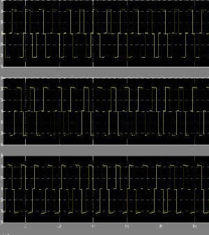
Fig.2b Inverter Output Voltage W aveform
The output of Z-filter is filtered, ripple free, pure DC and it is given to Embedded EZ-Source inverter. The inverter output voltage waveform is shown in fig.2b.The triggering pulses for switches of Embedded EZ-Source inverter is shown in fig.2c.
Fig.2c Triggering pulses for three-phase inverter
The Embedded EZ-Source inverter converts filtered, ripple free, pure DC in to three-phase balanced AC. The line voltage and line current of Embedded EZ-Source inverter are shown in figs. 2f and 2g respectively. Three-phase balanced AC thus obtained through Embedded EZ-Source inverter is fed to Asynchronous machine like induction motor for its effective control. The speed of induction motor increases and settles down above 1400 RPM.
.
IJSER © 2013 http://www.ijser.org
International Journal of Scientific & Engineering Research, Volume 4, Issue 4, April-2013 517
ISSN 2229-5518
Fig.2d Rotor Speed
The renewable energy resource as well the non renewable energy source and the controlled EZ Source inverter system is simulated using Matlab Simulink. The performance with motor load is observed. Renewable energy resource controlled EZ-Source inverter system is a viable three phase source since it has reduced harmonic distortion in the output.
[5] F. Z. Peng, A. Joseph, J.Wang, M. Shen, L. Chen, Z. Pan, E. Ortiz- Rivera, and Y. Huang, "Z-source inverter for motor drives," IEEE Trans. Power Electron., vol. 20, no. 4, pp. 857- 863, Jul. 2005.
[6] F. Z. Peng, M. Shen, and K. Holland, "Application of Z-source inverter for traction drive of fuel cell-Battery hybrid electric vehicles," IEEE Trans.Power Electron., vol. 22, no. 3, pp. 1054-1061, May 2007.
[7] Y. H. Kim, H. W. Moon, S. H. Kim, E. J. Cheong, and C. Y. Won, "A fuel cell system with Z-source inverters and ultracapacitors," in Proc. IPEAlC, 2004, pp.1587-1591.
[8] J. W. Jung and A. Keyhani, "Control of a fuel cell based Z-source converter," IEEE Trans. Energy Convers., vol. 22, no. 2, pp. 467-476, Jun. 2007.
[9] L. Palma, P. Enjeti, N. Denniston, and J. L. Duran-Gomez, "A converter topology to interface low voltage solar/fuel cell type energy sources to electric utility," in Proc. IEEE APEC, 2008, pp.135-140.
[10] P. Xu, X. Zhang, C. Zhang, R. Cao, and L. Chang, "Study of Z- source inverter for gridconnected PV systems," in Proc. IEEE PESC,
2006, pp. 1-5.
[11] B. Farhangi and S. Farhangi, "Comparison of Z-source and boost- buck inverter topologies as a single phase transformer-less photovoltaic gridconnected power conditioner," in Proc. IEEE PESC,
2006, pp. 1--6.
[12] P. C. Loh, D. M. Vilathgamuwa, Y. S. Lai, G. T. Chua, and Y. Li, "Pulse width modulation of Z-source inverters," IEEE Trans. Power 428
Electron., vol. 20, no. 6, pp. 1346-1355, Nov. 2005.
[13] M. Shen, J. Wang, A. Joseph, F. Z. Peng, L. M. Tolbert, and D. J. Adams, "Constant boost
control of the Z-source inverter to minimize current ripple and voltage stress," IEEE Trans. Ind Appl., vol. 42, no. 3, pp. 770-778, May/Jun.
2006.
[14] M. Shen and F. Z. Peng, "Operation modes and characteristics of the Z-source inverter with small inductance or low power factor," IEEE Trans.Ind Electron., vol. 55, no. 1, pp. 89-96, Jan. 2008.
I wish to thank my Project guide R.Sivaprasad who has helped me out with his knowledge and guidance throughout the project to make this as a successful move in terms of new findings and innovation. At the same time I would like to thank the lecturers of Sri Sai Ram Engineering College who has supported me with their experience and knowledge.
[1] F. Z. Peng, "Z-source inverter," IEEE Trans. Ind. Appl., vol. 39, no. 2, pp. 504-510, Mar./Apr. 2003.
[2] P. C. Loh, D. M. Vilathgamuwa, C. J. Gajanayake, L. T. Wong, and C. P. Ang, "Zsource current-type inverters: Digital modulation and logic implementation," IEEE Trans. Power Electron., vol. 22, no. 1, pp.
169-177, Jan. 2007.
[3] R. Antal, N. Muntean, and I. Boldea, "Modified Z-source single- phase inverter for single-phase PM synchronous motor drives," in Proc. OPTIM, 2008, pp. 245-250.
[4] L. Sack, B. Piepenbreier, and M. von Zimmermann, "Dimensioning of the Z-source inverter for general purpose drives with three2012
International Conference on Computing, Electronics and Electrical
Technologies [ICCEET] phase standard motors," in Proc. IEEE PESC,
2008, pp.1808-1813.
IJSER
respectively. His area of interest includes Renewable Energy, Energy saving, Electrical Machines and Power Electronics.

R.Sivaprasad is a research scholar of Anna University pursuing his research in the area of Electrical Drives under the guidance of Dr.V.Jamuna. He is currently working as Asst. Prof in the Department Of EEE, Sri Sairam Engineering College. He completed his Graduation in Electrical & Electronics
Engineering in the year 2003.Obtained Master’s Degree from CEG, Guindy in 2007. His areas of interest are Control Systems, Energy Saving, Electrical Machines and Drives.