supported on a 4.575 m simple span. The 1.07 m wide and 90 mm thick concrete slab was compositely connected to the steel
web along the full length of the beam.
International Journal of Scientific & Engineering Research, Volume 6, Issue 4, April-2015 1261
ISSN 2229-5518
Parametric Study of Composite Steel-Concrete
Beams with External Prestressing
Amer M. Ibrahim, Saad k. Mohaisen, Qusay W. Ahmed
Abstract— The main purpose of the present paper is to investigate the effect of several important parameters on the behavior of external prestressed composite steel-concrete beams. ANSYS computer program (version 12.0) has been used to analyze the three dimensional model. The nonlinear material and geometrical analysis based on Incremental-Iterative load method, is adopted. These parameters include effect of compressive strength of concrete, effective prestressing stress to ultimate stress ratio, effective height to center of prestressing cables ,effect of external prestressing technique , type of loading, tendon profile, degree of interaction , ratio of thickness to width of concrete slab , using unsymmetrical I-steel beams ,effect of number of stiffeners and effect Full and Partial Interaction.
Index Terms— ANSYS; Parametric study; Externally prestressed; Composite steel-concrete beams.
—————————— ——————————
xternally prestressed structures, initially developed for bridges, are now becoming popular in bridge construction and strengthening or rehabilitation of existing structures. Comparing with an internal pre- stressing system, an external prestressing system has some advantages, such as being simpler to construct
and easier to inspect and maintain.
The external prestressing of the steel or composite
beams is accomplished by means of high strength ten-
dons anchored at the two ends of steel beam. The cable
profile (straight or draped) is determined along the
beam axis by a specific number of saddles at which the
cable can slip. Externally prestressing of steel structures
or composite beams may be considered as a powerful economical alternative for strengthening the existing beams as well as for designing new beams.
Composite beams strengthened with prestressed tendons display several failure modes. These failure modes include (i) compression crushing of concrete (ii) yielding of steel beam web, (iii) shear failure, (iv) rupture of steel tendons. Out of these four failure modes, the fourth mode can be eliminated by providing special steel anchorages at the ends of and steel deviators along the tendons to eliminate stress concentrations. Shear failure can be prevented by providing sufficient shear studs on the steel beam, to be encased in concrete. The other two failure modes, namely, compression crushing of concrete and yielding of steel beam is considered the imported factors in composite steel-concrete beams failure.
There are many achievements for the prestressing tech- nique concerning both experimental and analytical can be found. Li et al. [1] investigated the fatigue behavior of compo- site steel-concrete bridges by strengthening bridges with ex-
————————————————
• Amer M. Ibrahim. Professor, Civil engineering, Diyila university, Iraq, E-
mail: amereng05@yahoo.com
• Saad k. Mohaisen Asst. prof., Civil engineering, Al-Mustansiriya Universi- ty, Iraq, E-mail: amereng05@yahoo.com
• Qusay W. Ahmed, Asst. lecturer, Civil engineering, Diyila university, Iraq,
E-mail: msc.qussay@yahoo.com
ternal tendons. They carried out parametric studies of the fa- tigue test for various components such as strands, shear studs, and cover plates and discussed the results by comparing them with the current bridge design specifications. Similarly, Dall’Asta and Zona [2] proposed a nonlinear finite element model simulating the behavior of beam tested by Ayyub et al. [7] to describe the structural behavior up to failure only ,while in this paper we will discuss the effect of ten parameters on the behavior of prestressed composite beam, also Dall’Asta and Zona used numerical equation procedure to analysis the model ,while we used a computer program (ANSYS) . Nie et al. [3] tested eight specimens considering different parameters
.The slip effect between the steel and concrete interface and the increase of the prestressing tendon force with the increase of loading were accounted. Choi et al. [4] illustrated a system- atic procedure of external post-tensioning technique for strengthening or rehabilitation of steel-concrete composite bridges based on the principle of virtual work. Xue et al. [5] investigated the Long-term behavior, the combined effects of creep and shrinkage of concrete and relaxation of prestressing tendons were considered. Recently, Zona et al. [6] introduced a new simplified method for evaluating the tendon traction increment at collapse and consequently the beam flexural strength without requiring a nonlinear analysis of the whole beam-tendon structural system. The method is based on the observation that the shapes of the axial strain and curvature distributions at collapse.
In this paper a finite element method using ANSYS computer program is used to investigate the effect of several important parameters on the behavior of prestressed composite steel- concrete beams. The simply supported composite steel- concrete beam tested by Ayyub et al. [7] has been selected to carry out the parametric study.
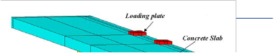
The beam is simply supported composite steel-concrete pre- stressed with external tendon and tested under positive bending moment by Ayyub et al. [7] As shown in Fig.1 , the beam is consisted of a concrete slab, a steel beam, and two prestressing tendons. The steel beam had a total length of 4.83 m and was
IJSER © 2015 http://www.ijser.org
International Journal of Scientific & Engineering Research, Volume 6, Issue 4, April-2015 1262
ISSN 2229-5518
supported on a 4.575 m simple span. The 1.07 m wide and 90 mm thick concrete slab was compositely connected to the steel
web along the full length of the beam.
The models that have been considered have a number of pa- rameters for each used element from element library in AN- SYS for analogue representation of the tested beam; these pa- rameters are summarized in Table 1.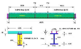
Fig. 1. Details of Beam. (All dimension in mm)
TABLE 1
Model Parameters for Used Elements in F.E. Model
(Units in Mpa)
In this study, the ANSYS computer program was used for ana- lyzing the prestressed composite steel-concrete beam with external tendon. A three dimensional element was used to representation the structure. Three-dimensional brick element with 8 nodes is used to model the concrete slab (SOLID65 in ANSYS) [8] . The element is defined by eight nodes having three degrees of freedom at each node: translations of the nodes in x, y, and z-directions. The concrete is assumed to be homogeneous and initially isotropic. The compressive uniaxial stress-strain relationship for concrete model is obtained by using the following equations to compute the multi-linear iso- tropic stress-strain curve for the concrete [9] as shown in Fig.2.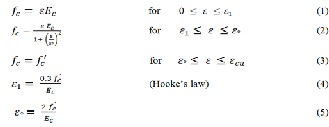
where
ε 1 =strain corresponding to (0.3fc'). ε O =strain at peck point.
ε cu = ultimate compressive strain.
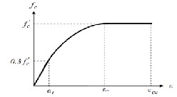
Fig. 2. Simplified Compressive Uniaxial Stress-Strain Curve for
Concrete .
To represent the steel beam in finite element, three- dimensional 4-node shell element (SHELL43 in ANSYS) is used. The element has six degrees of freedom at each node: translations in the nodal x, y, and z directions and rotations about the nodal x, y, and z axes. In contrast to concrete, the mechanical properties of steel are well known, and it is a much simpler material to be represented. The strain-stress behavior can be assumed to be identical in tension and com- pression. To avoid possible computational difficulties when using a computer, the alternative bilinear stress-strain rela- tionship indicated in Fig.3 is used [11].
In the present work, the strain hardening modulus (Et) is assumed to be (0.03 Es ). This value is selected to avoid con- vergence problems during iteration.
IJSER © 2015 http://www.ijser.org
International Journal of Scientific & Engineering Research, Volume 6, Issue 4, April-2015 1263
ISSN 2229-5518
Fig. 3 Bilinear Stress-Strain Relationship for steel
For reinforcement and prestressing bars modeling since the ordinary steel bars and prestressing cable are slender, they can be assumed to transmit axial force only. Modeling of ordinary steel and prestressed steel in finite element is much simpler. The stress-strain relationship for ordinary reinforcing steel and prestressing tendons can be represented as shown in Fig.
3.
A three-dimensional nonlinear surface-to-surface "contact-
pair" element was used to model the nonlinear behavior of the
contact surface between concrete slab and steel beam. (CON-
TA-173 in ANSYS) and the other represents rigid surface taken
as a target surface (TARGE-170 in ANSYS) [10]. In the present
work, coefficient of friction with (μ=0.7) has been used [12].
Sliding, which occurs when the normal stiffness (Kn) not equal
zero .For most contact analysis, ANSYS estimates values for
(Kn) as follows [15] .
After specifying the volumes and the areas, a F.E.analysis re- quires meshing of the model. In other words, the model is divided into a number of small elements, to obtain good results. After mesh- ing the beam the tendon is modeling, the use of a rectangular mesh is recommended. The width and length of elements in the interface surface is set to be consistent elements. The mesh used is shown in Fig.5 and the number of elements is shown in Table 2.
Kn =
f .Ec.h
(6)
Fig. 5. Volumes and Areas of Concrete and Steel Beam in ANSYS .
Where f = Contact compatibility factor (0.01-1.0), (FKN in ANSYS). Ec = Concrete Young’s modulus
h = Characteristic contact length
In the shear connector behavior the normal forces trans- mitted by the axial forces in the reinforcing bars are modeled by using a link element (LINK8 in ANSYS), while, the shear forces that are transmitted by shearing and flexure of the rein- forcing bars are modeled by using a nonlinear spring element (COMBIN39 in ANSYS). The nonlinear shear stiffness (Ks) of the dowel bars is given by [13]:
By taking advantage of the symmetry of both beam’s geome- try and loading, a half of the entire model beam in longitudi- nal direction is used for the finite element analysis. The aim of this was to reduce the computational time. The initial step of modeling involves creating key points for external points and certain locations such as support or loading and then creating lines between these key points to establish areas of steel beam and stiffeners then creating the volumes of concrete slab, an- chorages and steel plates. The origin of coordinates coincides with the center of external edge of beam, as shown in Fig.4.
TABLE 2
NUMBER OF ELEMENTS FOR TESTED BEAM
SER © 2015
International Journal of Scientific & Engineering Research, Volume 6, Issue 4, April-2015 1264
ISSN 2229-5518
Surface-to-surface contact elements are used to model interface be- tween concrete and top flange of the I-steel beam as shown in Fig.6.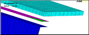
Fig. 6. Surface to Surface Contact Element.
Shear connectors consisting of two types of elements, (Com- bine 39 and link 8) are used to model stud shear connectors between concrete and I-steel beam. Combine 39 element locat- ed between two nodes, the first node on I-steel and the second node on concrete with the same position. The second element is Link8 consist of three nodes, the first one on I-steel flange while the second and third point in concrete elements , as shown in Fig. 7.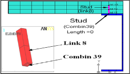
Fig. 7. Shear Connector Elements (Combine39, link8).
To model reinforcement bars, the discrete elements (LINK8) are used as shown in Figure (8). In spite of meshing of volumes for con- crete beam and areas for steel section, no mesh of the reinforcement is needed because individual elements are created in the modeling through the nodes created by the mesh of the concrete volume. By advantage of discrete model, the longitudinal and transverse rein- forcement are kept in their actual position.
Displacement boundary conditions are needed to constrain the model to get a unique solution. The boundary conditions need to be applied at points of symmetry and where the supports and loadings exist. Since one half of beam is taken in this model, one plane of symmetry is created. To model the symmetry, nodes on this plane must be con- strained in the perpendicular direction on it, as shown in Fig.9.
The supports are modeled in such a way a hinge and roller, that the beams in the present study simply support beam. To model the roller, a single line of nodes on the support are constraint in the vertical direction (Uy = 0), and constrains in the vertical and longitudinal direction give as hinge support ((Ux, Uy) = 0).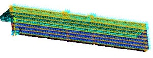
Fig. 9. Symmetry of One Half Beam.
For external loads a small bearing plate was placed between the loading and the concrete slab, to preventing concentration of stress in the concrete slab at the point of contact. Half of the loads (P/2) is applied because half model was used in our study, where the external load was applied by the equivalent nodal forces on the top nodes. The loads are applied on twenty nodes ten in each side.
In this study, the default of ANSYS program is used (convergence is checked by a force convergence criterion, tolerance equal to 0.001). The solution has been achieved by using the incremental-iterative techniques.
The main purpose of the parametric study is to investigate the influence of some parameters such as material properties or geometric changes in structure therefore ten parameters are taken in this study
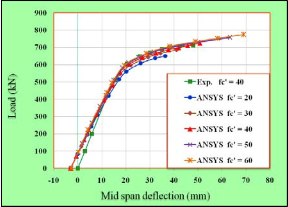
To study the effect of concrete compressive strength fc' of the concrete slab on the behavior of prestressed composite steel-concrete beam, different values of fc' were considered. These value were (20, 30, 40, 50, and 60) MPa. Fig. 10 shows the effect of compressive strength concrete slab on the load- deflection behavior of the selected beam. The Figure indicates that the stiffness of beam increases slightly with the increase of fc'. Also it is clear that the maximum predicated deflection is increase as the concrete compressive strength is increased.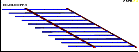
Fig. 8. Reinforcement Modeling in ANSYS for the Beam.
To discuss the effect of effective prestressing stress (fpe) on the behavior and ultimate load capacity of externally prestressed
IJSER © 2015 http://www.ijser.org
International Journal of Scientific & Engineering Research, Volume 6, Issue 4, April-2015 1265
ISSN 2229-5518
composite steel-concrete beam, different values of prestressing stress have been selected. Tendons have the same ultimate strength. The chosen values for ratio (fpe/ fpu) were (0.0, 0.25,
0.5 and 0.68). In this analysis only the value of effective pre- stressing stress was varied while all other parameters were kept constant. Effect of prestressing stress on the load- deflec- tion response of the beam can be noted from Fig.11. The Fig- ure reveals that for higher values of (fpe), the ultimate load is substantially increased. This can be attributed to the effect of the external prestressing force that tends to prevent the cracks from extending and improves the stiffness.
The effect of the effective height of the external prestressing tendon can be taken as different values for beam VS-2 where the values chosen are (30, 75, 125, 190 , and -30 ) mm from center of the bot- tom flange . The positive signs mean the tendon above the bottom flange of steel beam while the negative sign means that tendon be- low the bottom flange of steel beam. Typical numerical load deflec- tion curves for different values of effective height are compared with the experimental load-deflection curve (hpe = 30 mm) as shown in Fig.12. This Figure reveals that as a result of the decreasing effective height of externally prestressed tendon, the stiffness and ultimate load capacity are essentially increased. The predicated ultimate load is increased by average (18 %) when the tendon position change from (190 mm) to (-30 mm). This may be attributed to the increase in eccentricity of tendon which causes increase in its distance from the neutral axis, the greater the distance the higher the stress. Therefore, decreasing the tendon height to more has a signifi- cant effect on the ultimate strength capacity.
This section will compare the non-prestressed composite beam results with the externally prestressed composite beam results. Fig.13 shows the curves of load against mid-span de- flection for each beam. A comparison of the load-deflection curves illustrates that the prestressed beam deforms less than the non-prestressed beam, or behaves more stiffly. Both beams behaved quite linearly in the load-deflection curves before yielding of the steel bottom flange for non prestressed compo- site beam. The initial upward deflection had contributed to the lower deflection in the prestressed composite beam, and the tangents of the curves of prestressed composite beam are slightly greater than those of the non-prestressed beam before yielding of the steel beam, they appear quite similar. The rea- son should be the incremental prestress in the tendons, which is small and develops linearly with the exerted load before the yielding of the steel beam in prestressed composite beam, but increases much faster afterward. The results also demonstrate that adding prestressing to the composite beams significantly increased the yield load and the ultimate strength. It is noted the ultimate load for external prestressed composite beam is increased by 15.9 % which is larger than that of non- prestressed composite beam.
.
Fig.10 Effect of Compressive Strength of Concrete on the Load- Deflection Behavior of Beam Symmetry of One Half Beam.
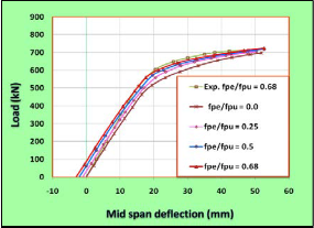
Fig.11 Effect of fpe/fpu Ratio on Load-Deflection Behavior of the
Beam
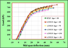
Fig.12 Effect of Effective Height of External Prestressing Tendon on Load-Deflection Behavior of Beam.
IJSER © 2015 http://www.ijser.org
International Journal of Scientific & Engineering Research, Volume 6, Issue 4, April-2015 1266
ISSN 2229-5518
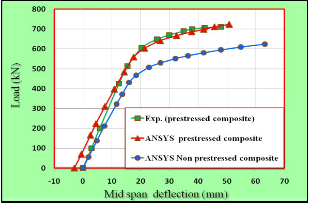
Fig.13 Load-Deflection Curves of External Prestressed Composite and non Prestressed Composite Beam.
The effect of the ratio of concrete slab depth to its width on the load-deflection behavior of prestressed composite beams and their ultimate loads are studied in this section. A different ra- tio of depth to width for concrete slab of VS-2 prestressed composite beam was taken in the finite element analysis. The selected ratios (t/B) were (0.086, 0.15, 0.2, and 0.25). In choos- ing these ratios, the total area of concrete slab was kept con- stant at (96300 mm2). Finite element mesh for all cases is illus- trated in Fig.14. Fig.15 shows the effect of depth to width ratio on the load-deflection behavior of selected beam. In this fig- ure, when the depth to width ratio increased, the ultimate load of has been increased distinctly. This is to be expected as an increase in thickness of slab would raise the neutral axis of the prestressed composite beam, hence increasing the eccentricity of tendon. The stiffness of beam is increased by increasing the depth to width ratio of concrete slab. Also it is clear that the maximum predicated deflection is decrease as the depth to width ratio of concrete slab is increased.
The present section focuses on the behavior of prestressed composite beam with full and partial interaction using the finite element software ANSYS. The results of the analysis of prestressed composite beams with full and partial interaction are presented in order to highlight the geometric nonlinear effects and how the ultimate loads are influenced by this ef- fect. For beam with full interaction analysis is found no slip between concrete slab and steel beam is occur while for the same beam with partial interaction (1.43) mm slip was record- ed at interface surface as shown in Fig.16.The finite element results obtained for the same beam assuming full and partial shear interaction are shown in Fig.17. It can be noted, that compared to a composite beam with partial shear interaction a stiffer behavior has been noticed. The ultimate load of the composite beam with full shear interaction was (764.3kN). The ratio of the ultimate load obtained using a complete shear in- teraction to the partial interaction value is (1.057).
In this section two cases of external tendon profile are chosen to discuss the effect of tendon profile on the load - deflection response for externally prestressed composite steel-concrete beam, straight profile in first case and two draped tendon profile with in second case. Fig.18 shows the results of load- deflection response for two cases. It can be seen in this Figure that the ultimate load capacity increases with draped tendon profiles compared to undraped profiles (straight tendon profile) where is produced the lowest nominal resistance. While no change in stiffness before yielding. After yield point the draped tendon will be stiffer than straight tendon.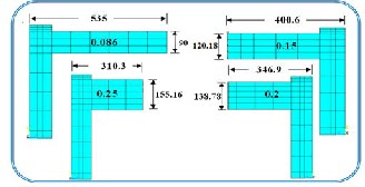
Fig.14 Finite Element Mesh for the Beam) with Different Depth to
Width Ratio of Concrete Slab.
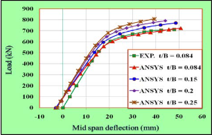
Fig.15 Effect of Effective Height of External Prestressing Tendon on Load-Deflection Behavior of Beam.
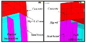
Fig.16 Numerical Relative Slip between Concrete and Steel for the Beam for Full and Partial Interaction
IJSER © 2015 http://www.ijser.org
International Journal of Scientific & Engineering Research, Volume 6, Issue 4, April-2015 1267
ISSN 2229-5518
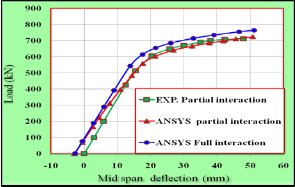
Fig.17 Effect of Degree of Interaction on the Load-Deflection
Behavior of beam.
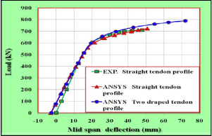
Fig.18 Effect of Tendon Profile on Load-Deflection Behavior of the
Beam.
The effect of load application on the load- deflection response was evaluated using three types of loading, namely, single concentrated load, two concentrated loads and four concen- trated loads. Results are shown in Fig.19 these results were obtained using straight tendon profile. The increasing of load on the beam subjected to four point loads is 45 % greater than that in beam with a single load at mid span. This is because, during loading, cracks started to appear and spread as the load increased. This continued up to formation of the plastic hinge where the strain concentrated and stress increased up to failure.
The effect of using unsymmetrical cross-section of steel beam on the load-deflection response of prestressed composite steel- concrete beams and their ultimate load are investigated in this section. The results are obtained by increasing the width of the lower flange of the steel beam to make its area as (A1 ) and decreasing the width of the upper flange of steel beam by the same amount to make its area as (A2 ). In this procedure the total area of steel beam cross-section was kept constant. Dif- ferent ratios of upper flange area to lower flange area (A1/A2 )
of the beam were taken in the numerical analyses. These ratios were (2.5, 1.6, 1.25 and 1.0), as shown in Fig.20. Fig.21 shows the effect of the upper to lower steel flange ratio on load- deflection response of prestressed composite steel-concrete beam. The overall behavior obtained from these tests ranges from stiff response when ratio (A1 /A2 ) was set equal to (2.5) to a relatively soft response for (A1 /A2 ) ratio equals to (1.0). Also, it has been observed that higher values of the ratio (A1 /A2 ) lead to an increase in the ultimate moment capacity.
In order to study the influence of stiffeners on the response of externally prestressed composite steel-concrete beams, differ- ent stiffener numbers is investigated for the beam, where the selected beam is used four pairs of stiffeners two under load and two at supports. The numbers were selected to study this effect are without stiffeners , two pairs of stiffeners , four pairs of stiffeners and six pairs of stiffeners. All beams were subject- ed to two concentrated loads. Comparison between the four types of beam on the behavior of load-deflection response is given in Fig.22.The load deflection curves indicate no differ- ences in behavior before yielding. While noted slightly differ- ence in stiffness for beams after yield load.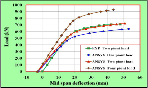
Fig. 19 Effect Type of Loading on Load -Deflection Behavior of the
Beam
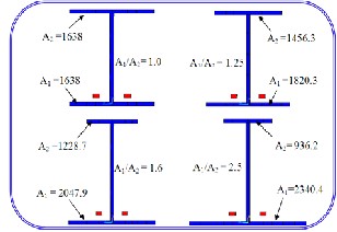
Fig.20 Finite Element Mesh for the Beam with Different Lower to
Upper Steel Flange Area Ratio. (all area in mm2)
IJSER © 2015 http://www.ijser.org
International Journal of Scientific & Engineering Research, Volume 6, Issue 4, April-2015 1268
ISSN 2229-5518
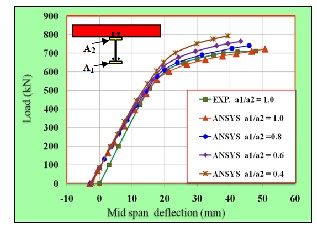
Fig.21 Effect of Ratio Upper Flange Area to Lower Flange Area on the Load-Deflection Behavior for the Beam..
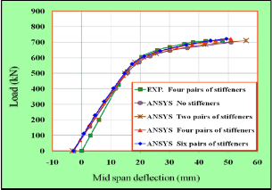
Fig.22 Effect of Number of Stiffeners on Load-Deflection Curve of the Beam.
3- It was found from the numerical analysis that the predicted ultimate loads are increased by 18% when the tendon position change from (190 mm) to (-30 mm).
4- It was observed that the increase in the ultimate load capacity for external prestressed beam by 15.9 % is larger than the same beam without external tendon.
5- The strength of composite beams are increased by increas- ing the ratio of the depth to width of concrete slab (t/B), with keeping the total area of concrete slab constant and it was found that as the (t/B) ratio is increased from 0.084 to 0.25 the ultimate load increases by about 11.68 %.
6- The finite element results obtained for the same beam as- suming full and partial shear interactions are shown that compared to a composite beam with partial shear interaction a stiffer behavior has been noticed. It was observed that the ultimate load capacity for beam with full interaction increase by 5.71 % is larger than the same beam with partial interac- tion.
7- It was found that the tendon profile has a clear effect on
the ultimate load capacity. The ultimate load increased 9.23 %
with two draped tendon profile compared to undraped pro-
file.
8- The increased in ultimate load on the beam subjected to
four point loads is 45 % greater than that in beam with a sin-
gle load at mid span.
9- It was found that the unsymmetrical I-section steel beam
with wider bottom flange used in prestressed composite steel-
concrete beam is more effective without change of total cross
section area. It was noticed that when the ratio of top flange
area to bottom flange area for I-section steel beam (A1/A2) is increased from 1.0 to 2.5, the ultimate load increased by about
9.7 %.
10- Stiffeners web plate has no significantly effect on the be-
havior of prestressed composite steel-concrete beams , where
the results showed that when increased number of stiffeners
to six pairs of stiffeners the ultimate load increased by about
3.3% . Beam with stiffeners and without stiffeners exhibit a
very similar load - deflection response.
[1] Li W., Albrecht P., and Saadatmanesh H. '' Strengthening of Composite Steel-Concrete Bridges'' ASCE, Journal of Struc-
A numerical nonlinear analysis model, based on the Finite Ele- tural Engineering, vol. 121, no. 12, December, pp.1842-1849 ment Method (FEM) using ANSYS computer program, was de- 1995.
veloped to investigate the effect of several factors on load- [2] Dall’Asta A. and Zona A. '' Finite Element Model for Ex- deflection response throughout the entire range of behavior us- ternally Prestressed Composite Beams with Deformable Con- ing the nonlinear analysis by ANSYS computer program. Effect nection '' ASCE, Journal of Structural Engineering, vol. 131,
of these factors can be summarized as follows:
no.5, May, pp.706-714, 2005.
1- From the numerical analysis carried out to study the effect of [3] Nie J., Cai C., Zhou T., and Li Y. ''Experimental and Ana- compressive strength of concrete on the strength behavior, it was lytical Study of Prestressed Steel-Concrete Composite Beams found that as the compressive strength of concrete is increased Considering Slip Effect '' ASCE, Journal of Structural Engi- from 20 N/mm2 to 60 N/mm2 the ultimate load is increased by neering, vol. 133, no. 4, pp. 530-540,April 2007.
about 18.9 %.
[4] Choi D., Kim Y., and Yoo H. ''External Post-tensioning of
2- For different values of effective prestressing stress that are Composite Bridges by a Rating Equation Considering the In- taken as fpe/fpu ratio, the ultimate load is increased substantial- crement of a Tendon Force Due to Live Loads'' Steel Struc- ly by about 3.74 % when the ratio is increased from 0.0 to 0.68. tures 8 , pp.109-118, June 2008,.
This can be attributed to increase in prestressing force that im- [5] Xue W., Ding M., He Ch., and Li J. '' Long-Term Behavior
proves the stiffness of beam.
of Prestressed Composite Beams at Service Loads for One
IJSER © 2015 http://www.ijser.org
International Journal of Scientific & Engineering Research, Volume 6, Issue 4, April-2015 1269
ISSN 2229-5518
Year '' ASCE, Journal of Structural Engineering, vol. 134, no. 6, pp.930-937, June 2008.
[6] Zona A., Ragni L., and Dall'Asta A. ''A Simplified Method for the Analysis of Externally Prestressed Steel-Concrete Composite Beams'', Journal of Constructional Steel Research
65, pp. 308-313, 2009.
[7] Ayyub B., Sohn Y., and Saadatmanesh H.'' Prestressed
Composite Girders under Positive Moment''.ASCE,Journal of
Structural Engineering,vol.116, no.11, pp. 2931-2951
,Nov.,1990.
[8] Amer M. Ibrahim, Qusay W. Ahmed '' Nonlinear Analysis
of Simply Supported Composite Steel - Concrete Beam'' vol.
06, no. 03, pp. 107-126, September 2013.
[9] Desayi P., and Krishnan, S., "Equation for the Stress-Strain Curve of Concrete", Journal of the American Concrete Insti- tute, Vol. 61, March 1964, pp. 345- 350.
[10] Amer M. Ibrahim , Saad k. Mohaisen , Qusay W. Ahmed
''Finite element modeling of composite steel-concrete beams with external prestressing'' International Journal of Civil And Structural Engineering, volume 3, no 1, 2012.
[11] European Committee for Standardisation (CEB), Euro- code 3, "Design of Steel Structures", Part 1.1: General Rules and Rules for Buildings, EC3, DD ENV 1993-1-1.
[12] ''ACI Committee 318'', Building Code Requirements for
Structural Concrete (ACI 318M-08) and Commentary (ACI
318RM-08)", American Concrete Institute, Farmington Hills,
2008.
[13] Ollgaard G., Slutter G., and Fisher W., "Shear Strength of
Stud Connectors in Lightweight and Normal Weight Con- crete", AISC Engineering Journal, vol. 8, no.2, pp. 55-64, 1971. [14] Millard S., and Johnson R., "Shear Transfer acrossCracks in Reinforced Concrete Due to Aggregate Interlock and to
Dowel Action" Magazine of Concrete Research, Vol.36, No.126, pp. 9-2, March 1984.
[15] Yousifani, A. H., “Investigation of the Behavior of Rein- forced Concrete Beams with Construction Joints Using Non- linear Three-Dimensional Finite Elements", M. Sc. Thesis, University of Technology, April 2004.
IJSER © 2015 http://www.ijser.org