effect of compressor inlet air-cooling and gas turbine blade cooling on t
ity correction factor represented by
Inte rnatio nal Jo urnal o f Sc ie ntific & Eng inee ring Re se arc h Vo lume 3, Issue 3 , Marc h-2012 1
ISSN 2229-5518
Parametric Analysis of Cooled Gas Turbine Cycle with Evaporative Inlet Air Cooling
Alok Kumar Mohapatra, Sanjay, Laljee Prasad
Abs tract— The article investigates the eff ect of compressor pressure ratio, turbine inlet temperature and ambient temperature on the perf ormance parameters of an air-cooled gas turbine cycle w ith evaporative cooling of inlet air. Air f ilm cooling has been adopted as the cooling technique for gas turbine blades. The mass of coolant required f or turbine blade cooling is calculated f or a selected range of ambient conditions and f ound to vary w ith temperature drop achieved in the evaporator. The eff ect of ambient temperature on p lant eff iciency and plant specif ic w ork is computed at dif ferent TIT and r p,c and it w as f ound that the rate of increase in these perf ormance
parameters are more pronounced at higher TIT and r p,c . The results indicate that a maximum temperature drop of 21 oC is achieved in the evaporator. The inlet cooling is found to increase the eff iciency by 4.1% and specif ic w ork by 9.44%. The optimum p lant perf ormance is
obtained at a TIT of 1500K and rp,c of 20 f or all values of ambient temperature .
—————————— ——————————
as turbines have gained wides pread acceptance in the power generation, mechanical drive, and gas trans miss ion markets . Their compactness , high power-to-weight ratio, and eas e of
installation have made them a popular prime mover. Improvements in hot s ection materials , cooling technologies , and aerodynamics have allowed increases in firing temperatures . I.G. Wright, T.B. Gib- bons [1] have thoroughly reviewed the recent developments in gas turbine materials and technologies . Consequently, thermal efficie n- cies are currently very attractive, with s imple cycle efficiencies rang- ing between 32 % to 42 % and combined cycle efficiencies reaching the 60% mark. The efficiency of the gas turbine cycle has been im- proved mainly due to enhanced gas turbine performance through advancements in materials and cooling methods in recent years .
Out of the various methods of improving the gas turbine performance, two important methods are by inlet air cooling and gas turbine blade cooling.
The highest losses in gas turbine power output usually coincide with periods of high electricity demand. A gas turbine loses approximately 7% of its nominal power when the intake t emperature increas es from 15 oC, ISO conditions , to 25 oC, and in cas es such as in s ummer when the ambient temperature increas es above 25 oC, the losses are s till bigger, reaching even 15% of the power rating with 36 oC. By the addition of an air-cooling sys tem at the compressor in- take, the inlet air can be conditioned to lower temperatures than a m- bient, thus improving plant performance at high ambient tempera- tures . As the inlet air temperature drops compressor work decreases and so the net work and cycle efficiency increases . In addition, air dens ity increases with drop in inlet temperature, which results in an increas e in mass flow rate of air entering the compress or and s o the power output is enhanced . De Lucia et al. [2] have s tudied gas tu r- bines with inlet air cooling and concluded that evaporative cooling
———— ——— ——— ——— ———
Alok Kumar Mohapatra is presently pursuing his PhD in Mechanical Engineer- ing at National Institute of Technology, Jamshedpur.Jharkhand,India -, PH-
09437208700 E-mail: m.alokkumar@gmail.com
could enhance the power produced by up to 4% per year. Hosseini et al. [3] have summarized that the output of a gas turbine of the Fars combined cycle power plant at 38 oC ambient temperature and 8% relative humidity is 11 MW more, and the temperature drop of the inlet air is about 19 0C with media evaporative cooling installations . Zadpoor and Nikooyan [4] concluded that evaporative inlet cooling sys tems do not work well in humid areas . Najjar [5] analyzed that the addition of abs orption inlet cooling improves the power output by about 21%, Overall thermal efficiency by about 38 % and overall specific fuel consumption by 28 %. Bass ily [6] carried out energy balance analys is of gas turbine cycles and reported that introducing indirect inlet air cooling, evaporative after cooling of the compressor discharge along with regeneration, intercooling, and reheat increase the performance s ignificantly. Wang and Chiou [7] calculated the expected benefits from the inclus ion of the inlet cooling feature is about 12% increase in power output and 5.16% increase in efficiency when the ambient temperature is cooled from 305 to 283 K. In addi- tion to this inves tigation by other researchers [8],[9],[10],[11] have
also been carried out in the field of inlet air cooling of gas turbine. The s earch for a better performance of gas turbine engines has also led to higher turbine inlet temperatures . However, the ma ximum value of TIT is res tricted by metallurgical limits of tu rbine blade material, which should be kept at 1123 K in order to protect the blades from damage. The TIT could be raised above this limit by us ing es pecial high temperature materials or coo ling the hot turbine components with a suitable coolant. The objective of the blade coo l- ing is to keep the blade temperature to a s afe level, to ensure a long creep life, low oxidation rates , and low thermal stress es . The unive r- s al method of blade cooling is by air bled from compressor flowing through the internal passages in the blades . Work in this area has been done by Louis et al. [12], Wu and Louis [13], El -Mas ri [14],[15], Bries h et al. [16], Bolland and Stadaas [17], Bolland [18], Chiesa and Macchi [19],Dechamps [20], and Sanjay et. al. [21],[22],[23],[24],[25 ] .
It is observed from a s tudy in the above-cited literatures that none of the previous work has investigated the s imultaneous
IJSER © 2012
Inte rnatio nal Jo urnal o f Sc ie ntific & Eng inee ring Re se arc h Vo lume 3, Issue 3 , Marc h-2012 2
ISSN 2229-5518
effect of compressor inlet air-cooling and gas turbine blade cooling on t
ity correction factor represented by
f h is introduced to take into
Ambient Air
Water for Air-Humidifier
Air Humidif ier
m f
GT Exhaust
CC
Cooled & Humid i-
fied Air
GT
C
A lternator
Bled Coolant Air
(Air Film Cooling)
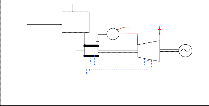
Fig. 1. Schematic of Air humidifier integrated gas turbine.
the mass of coolant required for gas turbine blade cooling is a function of inlet air temperature and reduces with increase in te m-
account the increase in s pecific humidity of ambient air across the air-humidifier and it is calculated as
perature drop.
The present work is an attemp t in this direction dealing with the combined effect of turbine blade cooling and evaporative inlet air-cooling on the performance of bas ic gas turbine cycle. The effects of compressor press ure ratio, turbine inlet temperature, a m-
bient relative humidity an d ambient temperature have been obs erved
f h 1 0.05h,e
where h,e is the relative humidity at the humidifier outlet. Thus , the enthalpy of gas is expressed as
(2)
on the thermodynamic performance parameters of the cycle.
T
h T c p
T dT
(3)
Parametric study of the combined cycle us ing different means of cooling has been carried out by modeling the various ele- ments of a gas turbine cycle and us ing the governing equations . The following are the modeling details of various elements . Figure 1 shows the s chematic diagram of a bas ic gas turbine cycle with inlet air humidifier and is being called air humidifier integrated gas tur- bine (AHIGT).
The specific heat of real gas varies with temperature and a l- so with pressure at extreme high pressure levels . However, in the pres ent model it is ass umed that specific heat of gas varies only with temperature in the form of polynomials as follows
c (T ) a bT cT 2 dT 3 .................................... (1)
where a, b, c, and d are coefficient of polynomials , as taken from the work of Touloukian and Tadash [26]. A factor called humid-
The enthalpy of ambient air entering the air-humidifier is ass igned zero value. In the model natural gas (NG) is the fuel us ed in combus tors and the compos ition and phys ical properties (s uch as
c p , g ,etc.) of burnt gas compos ition depend upon the compos ition of
NG that may vary from well-to-well (i.e. the s ource of NG). For
thermodynamic study, the fuel compos ition taken into account is CH4 = 86.21 %, C2 H6 = 7.20 %, and CO2 = 5.56 %, and N2 = 1.03 % by weight.
Cooling in hot, relatively dry climate can be accomplished by evaporative cooling. Evaporative cooling involves pass ing air across a spray of water or forcing air through a soaked pad that is kept replenished with water [27]. Owing to the low humidity of en- tering air, a part of the water injected evaporates . The energy re- quired for evaporation is provided by the air stream, which is unde r- goes a reduction in temperature. The following assumptions are made in the humidifier model.
The relative humidity at the humidifier outlet is 95%
IJSER © 2012
Inte rnatio nal Jo urnal o f Sc ie ntific & Eng inee ring Re se arc h Vo lume 3, Issue 3 , Marc h-2012 3
ISSN 2229-5518
The pressure drop of air in the humidifier is 1% of the a m-
8.314 3.653 1.337 103T
3.294 106
bient air pressure.
c
av
Applying the mass balance equation across the humidifier![]()
p , a
28.97 T 2 1.913 109 T 3 2.763 1013T 4
control volume boundary gives
a,e a,i mw
(4)
av av
av
(12)
where ω is the specific humidity and is calculated at a ce r- tain temperature as
cv,a c p,a
0.287
(13)
0.622 p
![]()
va p
p pva p
(5)
where
c p,vap and
cv,va p are the specific heats of water-
(w5h) ere
pvap psat is the partial pressure of vapour,
vapor at cons tant press ure and at cons tant volume respectively, both
in kJ/kg K, and are evaluated at the average temperature across the compressor from the following relations [27]:
is the relative humidity and
psa t
is the s aturation press ure of air
corresponding to the des ired temperature.
The energy balance equation for the humidifier is given by
h h
h
(6)
c 8.314
av
a,e
a,i
a,e
a,i w
4.07 1.108 103T
4.152 106
p,vap 2
9 3
13 4
Where
ha ,e
and ha ,i
are the enthalpy of moist air at
(6)
out-
18.02 Tav 2.964 10
Tav 8.07 10
Tav
(14)
let and inlet of the air humidifier res pectively and are calculated as
follows
cv,vap
c p,vap
0(.1446)14
(15)
ha,e
h
c p, a,e ta,e
c t
2500 1.88t
2500 1.88t
a,e
a,e
(7a)
(7b)
The enthalpy at any polytropic stage of compressor may be calculated us ing equations (1) , (3), and (8).
Us ing mass and energy balance across control volume of
a,i
p, a,in a,i
a,i
a,i
compressor, the compress or work is calculated as follows :
Ta,e ta,e 273
(7c)
m c,i
m
c.e
m
coolant, j
(16)
The equations (4 – 7) can be solved to determine the value
Wc m c,e hc,e m coolant, j hcoolant, j m c,i hc,i
(17)
of Ta ,e , a ,e
and mw .
The compressor us ed in gas turbine power plant is of axial flow type. The thermodynamic losses in an axial flow compressor are incorporated in the model by introducing the concept of polytrop- ic efficiency. The temperature and pressure of air at any s ection of compressor are related by the express ion
Loss es ins ide the combus tor, which arise due to incomplete combus tion and pressure loss es are taken into account by introducing the concept of combus tion efficiency and percentage pressure drop of compressor exit pressure [Table 1]. The mass and energy balances across the control volume of combustor yield the mass of fuel re-
quired to attain a specified exit temperature of combus tor which is
dT R
c
dp
(8)
taken as turbine inlet temperature (TIT), given by,![]()
![]()
![]()
T pt,c c p ,c
where pt,c
p
is the compressor polytropic efficiency and
m e m i m f
(18)
c p ,c
and
Rc are the specific heat at constant pressure and the gas
m f H r comb m e he m i hi
(19)
cons tant across the compressor res pectively.
Rc c p,c cv,c
where
cp,c cp,a aicp,vap
Rc is given by
(9)
(10)
Unlike s team turbine blading, gas turbine blading need cooling. The objective of the blade cooling is to keep the blade te m- perature to a s afe level, to ensu re a long creep life, low oxidation rates , and low thermal stress es . The univers al method of blade coo l-
cv,c cv,a
aicv,vap
(11)
ing is by air bled from compress or flowing through the internal pas-
s ages in the blades . In the case of film cooling, the coolant exits from
where c p ,a and cv ,a are the specific heats of air at cons tant
pressure and at cons tant volume respectively, both in kJ/kg K, and
are evaluated at the average temperature across the compress or from the following relations [27]:
the leading edge of blade and a film is formed over the blade s urface, which reduces the heat trans fer from the hot gas to the blade surface.
In this work, the gas turbine blades have been modeled to
IJSER © 2012
Inte rnatio nal Jo urnal o f Sc ie ntific & Eng inee ring Re se arc h Vo lume 3, Issue 3 , Marc h-2012 4
ISSN 2229-5518
be cooled by air-film cooling (AFC) method. The cooling model us ed for cooled turbine is the refined vers ion of that by Louis et al [12]. The mass flow rate of coolant required in a blade row is e x- press ed as [25]:
is an irrevers ible process and als o takes place along constant pressure line, which leads to drop in entropy. Process d 1-a2 in the model de- notes a process s imilar to throttling.
The deviation between actual and theoretical value is dri- ven by the amount of coolant and coolant temperature us ed for cool-
aco o la n t
![]()
m co o la n t
m g
(20)
ing of blades and the actual value varies with blade cooling require- ments . At TIT 1700K for air-film cooling, its maximum value is 6%
[25]. Turbine work and exergy destruction are given by the mass ,
Stin cp , g
Sg Fsa
Tg ,i Tb
energy and exergy balance of gas turbine as under:![]()
![]()
![]()
cp ,co o la n t
t cos
Tb Tco o la n t,i
Wgt
m (h h )
m coolant (hcoolant,i hcoolant,e )
where Sg 2c, Sg/tcos =3.0, Fs,a = 1.05, = 45 (for s ta-
tor), = 48 (for rotor), Stin=0.005.
Also blade coolant requirement is dependent on the te m- perature of coolant air at the bleed points , which in turn is dependent upon the temperature of air at the compressor inlet. With a drop in temperature of air at the inlet of co mpressor achieved in the humi- difier, there is a proportionate drop in the temperature of bled coolant due to more effective blade cooling achieved by lower temperature bled coolant and hence lesser coolant requirement. Als o, as the mass
The performance parameters Wgt, n e t
are expressed as follows :![]()
W
,Wpla nt ,
(21)
p la n t
,,,,,
of bled coolant is less , hence the quantum of pumping and mixing loss ass ociated with the mixing of coolant stream with main gas stream is also less .
Wgt, n et
W
Wgt
W
c
m
(22)
(23)
Polytropic
a1-b1 : Polytropic expansion
b1 -c1 : Energy loss due to cool-
plant
gt, net
W p la n t
alt
W p la n t
a ing
c1 -d1 : Energy loss due to mixing
![]()
p la n t
Q
![]()
m f
H r
(24)
p Polytropic expansion
Heat transfer process followed by mixing b with coolant, proc ess c
a2
d
p2+ p
d1-a2 : mixing stagnation pres- sure loss at constant en-
p2
Coolant mixing press ure drop
Modeling of cycle components and governing equations
developed for cycles propos ed above have been coded us ing C++ and results obtained. A flowchart of the programme code ‗Simu- comb‘ illustrating the method of s olution is detailed in the author‘s earlier article [25]. The input data us ed in the analys is is given in Table 1.
The influence of evaporative inlet air cooling on gas tu r-
Polytropic
bine performance has been s hown through the performance curves , plotted us ing modeling, governing equations and input parameters (Table1).
entropy, s
Fig. 2. Expans ion path in cooled gas turbine row
Fig. 2 gives the details of expans ion process for a cooled turbine s tage. Process b 1-c1 in Fig. 2 depicts cooling due to heat trans fer between hot gas and coolant, which takes place at cons tant pressure line due to which exergy decreases , while process c 1-d1 depicts drop in temperature due to mixing of coolant with gas which
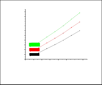
Fig. 3 s hows a plot illustrating the nature of varia- tion of specific heat of air as its temperature rises due to compress ion process through the compressor It is clear from the graph the specific heat of air is a function of temperature and specific heat of air is higher for higher values of temperature at the inlet of compress or
Fig. 4 depicts the variation in mass of turbine blade coolant required with respect to ambient temperature at various values of TIT in an air-humidifier integrated gas turbine. It can be seen that as the a m- bient temperature increases , though the drop in temperature achieved in the humidifier is more (due to higher difference between WBT and DBT) the temperature of air entering the compressor is also higher than des ign ISO condition. This results in higher amount of
IJSER © 2012
Inte rnatio nal Jo urnal o f Sc ie ntific & Eng inee ring Re se arc h Vo lume 3, Issue 3 , Marc h-2012 5
ISSN 2229-5518
coolant bleed from the compressor as per dis cuss ions detailed in s ection 2.5 above. It is worthwhile to note that the coolant require- ment in air-humidifier integrated gas turbine will always be less er than in a gas turbine without inlet-air humidifier.
0.162
0.160
Air-Humidifier Integrated Gas Turbine
TIT=1700K, RH =20%
a
0.158

0.156
1.12
1.11
1.10
1.09
0.154
0.152
0.150
0.148
0.146
1.08
0.144
1.07
1.06
1.05
1.04
1.03
0.142
285 290 295 300 305 310 315 320
Ambient Temperature(K)
Fig.5. Ef fect of ambient temperature on coolant f low rate at var ious rp,c in an AHIGT.
250 300 350 400 450 500 550 600 650
Average temperature of air through the compressor (K)
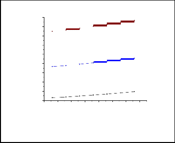
Fig. 3. Variation of specif ic heat of air w .r.t. average air temper- ature through the compressor
Air-Humidifier Integrated Gas Turbine
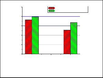
The Fig. 6 (a) and (b) s hows a his togram of the s ens itivity of plant efficiency and plant specific work to ambient air temperature for fixed values of TIT and rp,c in the cas e of air-humidifier integrated gas turbine. The his togram illus trates the advantage of inlet air- cooled GT cycle over the bas ic GT cycle without inlet air-cooling in terms of enhancement in plant efficiency and plant specific work. It is obs erved that both plant efficiency and s pecific work of inlet air- cooled GT cycle are higher than that without inlet air cooling for a
given ambient temperature. For a given relative humidity, as the a m-
0.16
0.15
0.14
0.13
0.12
r =23, RH =20%
p,c a
bient temperature increas es , an improvement in plant efficiency and specific work is obs erved due to inlet cooling (though the efficiency is reduced for both the cas es ). This is because at higher ambient tem- perature the difference between wet and dry bulb temperature is higher resulting in more effective cooling of inlet air, leading to larg-
er temperature drop in the humidifier and hence lesser coolant re-
0.11
0.10
0.09
0.08
quirement. The values of plant s pecific work and plant efficie ncy compares well with publis hed works and exis ting gas tu rbines with variation in the range of 2.5 to 3% as shown in table. 1
0.07
285 290 295 300 305 310 315 320
Ambient Temperature(K)
Fig. 4. Eff ect of ambient temperature on coolant f low rate at various values of TIT in an AHIGT.
40
r
p,c
38
36
=23, TIT=1700 K
Without inlet air cooling
With evaporative inlet air cooling
Fig. 5 depicts the variation in mass of blade coolant required with respect to ambient temperature at different compressor pressure ratio. The coolant requirement increases with increas e in ambient tempera- ture and is higher at higher value of rp,c. The enhanced coolant re- quirement is due to higher temperature of bleed air at respective bleed points , which achieve lower level of blade cooling effectiv e- ness . It can also be observed that the cooling requirement at higher values of rp,c is als o higher at higher values of temperature as per discuss ions detailed in s ection 2.5 above.
34
32
30
RHa=20%,Ta=288K -- RHa=20%,Ta=313K
Ambient Temperature
Fig 6 a. Ef fect of ambient temperature and evaporative inlet air cooling on plant eff iciency
IJSER © 2012
Inte rnatio nal Jo urnal o f Sc ie ntific & Eng inee ring Re se arc h Vo lume 3, Issue 3 , Marc h-2012 6

ISSN 2229-5518
400
350
300
250
r
p,c
=23, TIT=1700 K
Without inlet air cooling
With evaporative inlet air cooling
As the compress or inlet temperature increases , the compressor work is increased and the mass of coolant required increas es correspon- dingly as per dis cuss ions detailed in s ection 2.5 above. Although the fuel cons umption is reduced for a given TIT, the drop in plant specif- ic work due to ris e in mixing and cooling losses owing to higher amount of coolant required and the increase in compressor work due to higher compressor inlet temperature together res ults in a net re- duction in plant specific work and plant efficiency. It is als o found from the graph that the rate of increas e in efficiency is more pro- nounced at higher TIT.
200
RHa=20%,Ta=313K -- RHa=20%,Ta=313K
Ambient Temperature
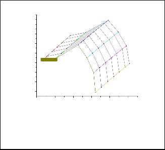
Fig. 8 depicts the effect variation of rp,c and drop in temperature achieved in the evaporator , on plant specific work and plant effi- ciency. It is obs erved that the specific work and efficiency increases with increase in temperature drop of air achieved in the h umidifier,
Fig 6 b. Ef f ect of ambient temperature and evaporative inlet air
cooling on plant specif ic w ork
Fig. 7 depicts the effect of TIT and drop in temperature achieved in the evaporator (due to increase in ambient temperature) on turbine efficiency and s pecific work. It is interes ting to note that the efficie n- cy and specific work reduces even when there is a drop in the te m- perature of air. This is becaus e at higher air ambient temperature, though the drop in temperature is higher, owing to higher difference between WBT and DBT, the compress or inlet temperature is also high. At an ambient temperature of 318 K the humidifier produces a drop of 20 K res ulting in a compressor inlet temperature of 298 K. In comparison at 293 K a mbient temperature though the temperature drop across the humidifier is only 11 K, the compressor inlet tempe r- ature is als o lower (284 K). However, as the ambient temperature increas es due to higher drop in temperature achieved in the evapora- tor, the diminution in efficiency and s pecific work is not as pro-
the enhancement being higher in higher range of rp,c. The inlet air cooling boos ts the efficiency by 3.44 % at rp,c=23, RHa=20% and a TIT of 1300 K when the ambient temperature drops by 300C. This enhancement increas es to 4.1% for a TIT of 1800 K at the same va l-
ue of rp,c, RHa and ambient temperature drop. The effect of variation of rp,c on plant specific work s uggests that s pecific work s lightly in- creas es with increase in pressure ratio for all range of specific hu- midity after which it decreases . It is also obs erved that the rp,c corres- ponding to maximum s pecific work increases with increase in te m- perature drop achieved in the humidifier. This sugges ts that for a higher value of plant specific work there exis ts an optimum value of rp,c (for a given temperature drop achieved in the humidifier) and the rp,c needs to be chos en judicious ly.
Air-Humidifier Integrated Gas Turbine
TIT=1700, RH = 20%
a
nounced as in the cas e of a gas turbine cycle without inlet cooling as per dis cuss ions detailed for Fig. 6(a) above.
40.5 Air-Humidifier Integrated Gas Turbine r =23, RH = 20%
0.40
0.39
0.38
0.37
Rpc=30
Rpc=28
Rpc=26
Rpc=24
Rpc=22
Rpc=20
pc a
40.0
39.5
39.0
38.5
0.36
0.35
0.34
0.33
Rpc=18
Rpc=16
38.0
370 380 390 400 410 420
Gas cycle specific work
37.5
37.0
36.5
320 340 360 380 400 420
Plant specific work (kJ/kg)
Fig 7. A design monogram of eff iciency versus specif ic w ork in an AHIGT f or diff erent TIT and drop in temperature of air in the humidif ier due to rise in ambient temperature
Fig 8. A design monogram of plant eff iciency versus plant specif- ic w ork in an AHIGT f or diff erent TIT and and drop in temper a- ture of air in the humidif ier
.
.
IJSER © 2012
Inte rnatio nal Jo urnal o f Sc ie ntific & Eng inee ring Re se arc h Vo lume 3, Issue 3 , Marc h-2012 7
ISSN 2229-5518
TABLE 1
INPUT DATA FOR ANALYSIS [25, 28]
PARAMETER | SYMBOL | UNIT |
Gas Pr oper- ties: | Cp=(T) Enthalpy h=cp(T) dT | kJ/kg k KJ/kg |
Air - Humidifier | Pr essur e drop acr oss humidifier = 1 Wetted Pad, Cr oss flow type | % - |
Compr essor | Polytr opic efficiency(p,c)=92.0 Mechanical efficien- cy(m)=98.5 Air inlet temperatur e = 288 Inlet plenum loss= 0.5% of entry pr essur e | % % K bar |
Combustor | Combustor efficiency (comb)=99.5 Pr essur e loss (ploss)=2.0% of en- try pr essur e Low er heating value (LHV)= 42.0 | % bar MJ/kg |
Gas turbine | Polytr opic efficiency (pt)=92.0 Exhaust pr essur e=1.08 Exhaust hood loss=4 Turbine Blade Temperatur e= 1123 | % bar K K |
Alternator | Alternator efficiency=98.5 | % |
J = joule, kg = kilogram, K = kelvin.
Bas ed on the analys is of air-humidifier-integrated-gas turbine cycle following conclus ions have been drawn:
1. The mass of coolant required for turbine blade cooling in-
creas es with increase in ambient temperature for an air hu- midifier integrated gas turbine.
2. The coolant mass tends to increase with ris e in TIT and rp,c
for a given ambient condition.
3. The plant performance parameters e.g. plant efficiency and plant specific work increas es because of inlet cooling us ing air-humidifier integrated to a gas turbine plant.
4. The enhancement in efficiency and s pecific work due to in- let-air cooling is higher at higher ambient temperature.
5. Gas turbine plant efficiency increases upto TIT of 1500 K
where after it decreases .
6. The rate of increase in plant efficiency due to reduction in compressor inlet temperature is more pronounced at higher TIT.
7. Optimum plant performance is obs erved at TIT of 1500 K
for all values of drop in temperature (Ta,dr = 08 oC to 20 oC)
8. The compressor pressure ratio corres ponding to ma ximum specific work increas es with increas e in temperature drop achieved in the humidifier.
9. The des ign monograms presented above can be used by power plant des igner in selecting the optimum operating parameters as per the s ite condition.
[1] I.G. Wright , T.B. Gibbons, ― Recent dev elopment s in gas t urbine mat erials and t echnology and t heir implicat ions for syngas firing‖ :International Journal of Hydrogen Energy 32 , (2007) 3610 – 3621.
[2] M. De Lucia , C. Lanfranchi, and V. Boggio,‖ Benefit s of compressor inlet
air cooling for gas t urbine cogenerat ion plant s‖ : In Proceedings of the In- ternational Gas Turbine and Aero engine Congress and Exposition , Hou- ston, Texas, 5–8 June 1995.
[3] R. Hosseini, A. Beshkani, M. Soltani, ―Performance improvement of gas t urbines of Fars (Iran) combined cycle power plant by int ake air cooling us- ing a media evaporat ive cooler ‖ : Energy Conversion and Managem ent 48 (2007) 1055–1064
[4] Amir Abbas Zadpoor and Ali Asadi Nikooyan, ―Development of an Im- proved Desiccant-Based Evaporat ive Cooling Syst em for Gas T urbines ‖ : J. Eng. Gas Turbines Power 131, 034506 (2009)
[5] Yousef S. H. Najjar, ―Enhancement Of P erformance Of Gas Turbine E n-
gines By Inlet Air Cooling And Cogenerat ion Syst em‖ : Thermal Engineer- ing, 1996, Vol 16. No. 2. pp. 163-173.
[6] A.M. Bassily, ―P erformance improvement s of the int ercooled reheat rege-
nerat ive gas t urbine cycles using indirect evaporat ive cooling of the inlet air and evaporat ive cooling of the compressor discharge ‖ : Proceedings of the Institution of Mechanical Engineers Part A Journal of Power And Energy (2001) Vol. 215, , pp: 545-557
[7] F.J. Wang, J.S. Chiou, ―Integrat ion of st eam inject ion and inlet air cooling
for a gas t urbine generat ion syst em‖ :Energy Conversion and Managem ent
45 (2004) 15–26.
[8] S. Hamlin, R. Hunt , S.A. Tassou , ― Enhancing the performance of evapor a- t ive spray cooling in air cycle refrigerat ion and air condit ioning t echnolo- gy‖ : Applied Therm al Engineering 18 (1998) 1139-1148
[9] A.M. Bassily, ― Effect s of evaporat ive inlet and aft ercooling on t he recup e- rat ed gas cycle‖: Applied Thermal Engineering, 21(2001) 1875 -1890H. Go- to, Y. Hasegawa, and M. Tanaka, “Efficient Scheduling Focusing on the Duality of MPL Representation,” Proc. IEEE Symp. Computational Intelligence in Scheduling (SCIS ’07), pp. 57-64, Apr. 2007,
doi:10.1109/SCIS.2007.367670 . (Conference proceedings)
[10] E. Kakaras, A. Doukelis, S. Karellas, ― Compressor intake-air cooling in gas t urbine plant s‖ : Energy 29 (2004) 2347–
[11] M.M. Alhazmy , Y.S.H. Najjar, ― Augment at ion of gas t urbine performance using air coolers‖ : Applied Thermal Engineering 24 (2004) 415–429.
[12] J.F. Louis, K. Hiraoka, and M.A. El-Masri, A comparat ive st udy of influence
of different means of t urbine cooling on gas t urbine performance, ASME Paper no. 83-GT-180.
[13] Wu Chaun Shao and J.F. Louis, A comparat ive st udy of the influence of
different means of cooling on t he performance of combined (Gas and St eam Turbines) cycle. Trans. of ASME Journal of Engineering for Gas Turbines and Power; 106(1984): pp 750-755.
[14] M.A. El-Masri, GASCAN- An int eract ive code for thermal analysis of gas
t urbine syst ems, Trans. of ASME, Journal of Engineering for Gas Turbines and Power,; 110(1988): pp 201-209
[15] M.A. El-Masri, On thermodynamic of gas t urbines cycle – Part -2 – A model for expansion in cooled t urbines‖, Trans. of ASME, Journal of Engineering for Gas Turbines and Power, 108(1986), pp:151-159
[16] M.S. Briesh., RL Bannist er, IS Diakunchak, and DJ Huber., A combined
cycle designed t o achieve great er than 60 percent efficiency. ASME Journal
IJSER © 2012
Inte rnatio nal Jo urnal o f Sc ie ntific & Eng inee ring Re se arc h Vo lume 3, Issue 3 , Marc h-2012 8
ISSN 2229-5518
of Engineering For Gas Turbine And Power, 117(1995): pp. 734 -741.
[17] O. Bolland and J.F. Stadaas, Comparative Evaluat ion of combined cycles and gas t urbine syst ems with inject ions, st eam inject ion and recuperat ion, ASME Journal of Engg. For Gas Turbine and Power, 117(1995):pp. 138-
145.
[18] O. Bolland, A comparative evaluat ion of advanced combined cycle alt ern a- t ives., ASME Journal of Engg. For Gas Turbine and Power, 113(1991):pp.
190-197.
[19] Chiesa and Macchi, A thermodynamic analysis of different opt ions to break
60 % elect rical efficiency in combined cycle power plant s, Proceedings of the ASME Turbo-Expo 2002, June 3-6 2002, Amsterdam, ASME paper no. GT 2002-30663.
[20] P.J. Dechamps, Advanced combined cycle alt ernat ives with lat est gas t ur-
bines. ASME Journal of Engg. For Gas Turbine and Power, 120(1998):
350-357.
[21] Sanjay, Onkar Singh, B.N.Prasad, Energy and Exergy Analysis of St eam
Cooled Reheat Gas-St eam Combined Cycle, Applied Thermal Engineering
27 (2007) 2779–2790.
[22] Sanjay, Onkar Singh, B.N Prasad, ―Influence of Different Means of Tur- bine Blade Cooling on the Thermodynamic P erformance of Combined Cycle‖ Applied Thermal Engineering 28 (2008) 2315–2326.
[23] Sanjay, Onkar Singh, B.N. P rasad, ― Comparat ive P erformance Analysis of
Cogenerat ion Gas T urbine Cycle for Different Blade Cooling Means‖ Inter- national Journal of Thermal Sciences, Volume 48, Issue 7, July 2009, 1432-
1440.
[24] Sanjay, Onkar Singh, B.N. Prasad, ― Comparat ive evaluat ion of gas t urbine power plant performance for different blade cooling means‖ Proc. IMechE Vol. 223 part A: J. Power and Energy, pp. 71 -82
[25] Sanjay, Invest igat ion of effect of variat ion of cycle parameters on t herm o-
dynamic performance of gas/ st eam combined cycle, Energy, 36 (2011) pp.
157-167.
[26] Y.S Touloukian, and Makita Tadash, Thermo -physical P ropert ies of Matter, Vol. 6, The TP RC Dat a Series, IFI/PLENUNM, New York, Washington,
1970.
[27] M.Moran, , and H.Shapiro, , ― Fundamentals of Engineering Therm od y- namics‖: ,3rd edit ion, 1995 (John Wiley, New York).
[28] Gas T urbine World, Pequot Publishing Inc. vol. 32(1).
IJSER © 2012