International Journal of Scientific and Engineering Research, Volume 4, Issue 7, July 2013
ISSN 2229-5518
PS2 and USB Data Transmission Protocols
Shivang Ghetia, Suvigya Tripathi, Ankit Gupta
2091
Abstract-- As world go for new technologies; it needs different data transmission protocols which can transfer data more efficiently and effectively. In this review paper two most widely data transferring protocols which are used in computer named PS2 and USB Protocols are explained. Working, connections, different terms regarding protocols and the application of these protocols are explained in this review paper.
Index Terms-- PS2, USB, resolution, scaling factor, clock sequence, bus, synchronous-asynchronous transmission
—————————— ——————————
1 INTRODUCTION
HIS document is review of the most widely used data transferring protocol i.e. PS2 and USB. The name PS2 is
driven from IBM Personal System 2 by series of personal computers which was introduced in 1987.When the personal computer were introduced in market the mainly used data transmission protocol was PS2 protocol. But as the invention went on, a more compatible protocol introduced named USB, it came over PS2 and in personal computers it replaced PS2 without any change in internal hardware. There are many hardware devices introduced in market that use USB for data transmission .The main use of USB is USB Flash drive that has made the work more easy, faster, and efficient.
The pin configuration of the PS2 Protocol is given below
and it has 6 pins among them only 4 pins are used and rest is left unused.
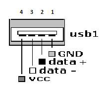
FIG.2 USB Connections
Pin 1. Ground Pin 2. Data+ Pin 3. Data-
Pin 4. Vcc (+5 V)
Pin 1. Data pin
Figure 1. PS2 Connections
Courtesy: Stephen A. Edwards
2 PS2
2.1 PS2 Protocol
Introduced in 1987 and mainly focused on the transmission of data between Mouse/Keyboard and Computer. For keyboard PS2 implement a bidirectional synchronous protocol in such
Pin 2. Not connected
Pin 3. Ground Pin 4. Vcc (+5 V) Pin 5. Clock
Pin 6. Not Connected
Similarly the pin configuration of the USB port is given below and it also has for pins and their specification is given below the figure 2.
————————————————
Shivang Ghetia has done bachelors degree program in electronics and communications in Nirma University, India.
E-mail- shivang.ghetia@gmail.com
Suvigya Tripathi has done bachelors degree program in electronics and communications in Nirma University, India.
Ankit Gupta has done bachelors degree program in electronics and communications in Nirma University, India.
manner that least significant bit comes first. The bus is ideal when both lines are high .This is the only state where the keyboard/board is allowed begin transmitting data.
2.2 Electrical Interface for Keyboard
The PS2 interface is a bit serial interface with two signal Data and Clock .Both signals are bidirectional and logic 1 is electrically represented by 5V & logic 0 is represented by 0 V Means Digital ground .Whenever the Data and Clock line is not used, i.e. is ideal, both the data and Clock lines are left floating, that is the host and the device both set the outputs in high impedance .Externally, at the PCB, large pull-up resistors keep the idle at 5 V (logic 1).
The figure 3 shows the interface of keyboard .When the FPGA (Field Program Gate Array) reads the data or clock inputs both PS2 data_out and dataclk_out are kept low which
IJSER © 2013
http://www.ijser.org
International Journal of Scientific and Engineering Research, Volume 4, Issue 7, July 2013
ISSN 2229-5518
2092
puts the tri-state buffers in high impedance mode. When the DPGA writes logic 0 on an output, the corresponding x_out signal is set high which pulls the line low .When writing logic
1 the FPGA simply sets the x_out signal low
Figure 3 Interface with keyboard
Courtesy: Jonus Thor
2.3 Protocol for receiving data from the keyboard by
PS2
Data is receiving from the keyboard as illustrates in figure 4.
Figure 4. Receiving Data from Keyboard
Courtesy: Jonus Thor
a. 1 start bit. This is always 0
b. 8 data bits, least significant bit first.
c. 1 parity bit (odd parity).
d. 1 stop bit. This is always 1.
The keyboard writes a bit on the data line when clock is high and it is read by the host when it is low .The parity bit is set if there is an even number of 1’s in the data bit and reset if there is an odd number of 1’s in the data. This is used for error correction and detection. The keyboard must check this and if incorrect it should respond as if it had received an invalid command.
Figure 5
Courtesy: Stephen A. Edwards
The above figure denotes the timing of PS2.In which the clock frequency is 10-16.7 KHz. [5] The timing from the raising edge of a clock pulse to a data transition must be at least 5 msec. The timing from a data transition to falling edge of a clock pulse must be at least 5 microseconds and no greater than 25vmsec.
2.4 Decoding Scan Codes
Keyboard’s processor spends most of its timing scanning and monitoring the matrix of keys. If it finds that any key is being pressed, released or held down, the keyboard will send a packet of information known as a scan codes .A break code is sent when a key is released .Every key is assigned its own unique make code and break code so the host can determine exactly what happened to which key by looking at a single scan code .The set of make and break code for every key comprises a Scan Code Set (Table 1).
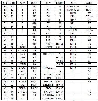
Table 1 Keyboard Keys and their scan codes
2.5 Mouse Interfacing
Using PS2 protocol mouse can be used as the interfacing hardware and a mouse can be very good decoder in reference of displacement measurement and when the Cartesian coordinate is concerned.
The PS2 port is similar to serial port(perform the function
of data receiving and transmitting ) expect for the fact that inserted of using baud rates the ports uses the in-out clock to transmit and receive the data .Data is sent on synchronous clock . For the PS2 protocol the data packets that are received and sent need to be of length as explained above in the case of keyboard interfacing.
On the movement of mouse it sends the 3 bytes of information
to the PS2 port. [7] The content of the data packet is described
IJSER © 2013
http://www.ijser.org
International Journal of Scientific and Engineering Research, Volume 4, Issue 7, July 2013
ISSN 2229-5518
2093
below in the figure 6.
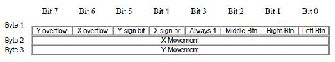
Figure 6
A USB device can be attached, configured and used, reset and again reconfigured and used. The host schedules the sharing of Bandwidth among the attached devices at an instant. While attaching or detaching process, there is no need of rebooting. The device is self-powered or gets from the host, external supply is not needed.
Courtesy: Stephen A. Edwards
Byte 1 contains the information on the direction the mouse moved with respect to its previous position, status of the mouse buttons and the x and y overflows which are set if the counter goes past 255. Byte 2 and 2 contains information regarding the x movement and the y movement respectively. The x movement and y movement are calculated of the basis of the counter values in the mouse. The counter gets incremented by a value of 4 for a movement of 1 mm on the screen. [7] Communicating with the mouse accordingly can change this resolution .The PS2 mouse also allows scaling value of the mouse movements.
The PS2 mouse sends to byte of data AA and 00.The AA
signifies the mouse passed its self-test and the 00 stands for the mouse ID. Once this information is received and checked the driver issues a mouse reset and waits for acknowledgement .After this mouse variable such as scaling factor, resolution etc. are set by transmitting the appropriate data to the mouse. After each transmission to the mouse the driver makes sure to check that acknowledge is received if not it performs the action again. Once all the variables are set enable signal is to send the mouse asking it to start recording.
3 USB
USB (Universal Serial Bus) is an industry standard developed in mid 1990s that defines cables, connectors and protocols used for connection, communication and power supply between and electronic devices. It was compatible with the already existing PS2 devices. USB is intended to make all the peripheral devices used on computer, ranging from keyboards, pointing devices to smart phones and video game consoles. It also eliminates need of separate power charges for portable devices. From its beginning in 1994, many versions of USB are released, each with increasing data transfer rate. The latest is USB 3.0, having transmission speed of up to 5Gbit/s, which is 10 times faster than USB 2.0 (480 Mbit/s).
3.1 USB Interface
It establishes a serial transmission and reception between host and serial devices, using a bus system, hence the name USB. The data transfer is of 4 types:
a) Controlled data transfer b) Bulk data transfer
c) Interrupt driven data transfer d) Iso-synchronous data transfer
Following is an example showing connections of USB
devices with host, resulting in creation of nodes/hubs. If the
peripheral is capable of supporting another USB device, it is a hub. All peripheral devices are essentially nodes.
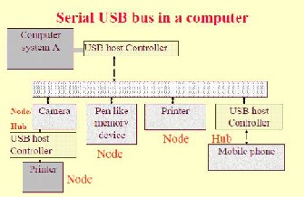
Figure 7
Courtesy: Raj Kamal
3.2 USB Protocol
A maximum of 127 devices can be connected to a source. The USB bus cable has 4 wires, one for +5 V, two for twisted pairs and one for ground.
Termination impedances at each end are according to the device speed. An electromagnetic Interference (EMI) shielded cable is used for the 15 Mbps USB devices. Serial signals are sent using NRZI (non-return to zero) encoding scheme. The synchronization clock is encoded by inserting synchronous code (SYNC) field before each USB packet. The receiver synchronizes its bits recovery clock continuously during the process.
There is a polled bus, through which the hot controller
regularity polls the presence of a device as scheduled by
software. It sends a token packet, which consists of fields for
type, direction, USB device address and device end point
number. To indicate successful transmission, the device
performs a ‘handshaking’ operation with host. The error detection is permitted by the presence of a CRC field in data
packet.
USB supports 3 types of pipes:
a) Stream: It does not have any USB-defined protocol. It is used when the connection is already established and the data starts flowing
b) Default control: it is for providing access
c) Message: it is for the control functions of the device [8]
IJSER © 2013
http://www.ijser.org
International Journal of Scientific and Engineering Research, Volume 4, Issue 7, July 2013
ISSN 2229-5518
3.3 USB Keyboard Interfacing
2094
Like ps2 here also bits and bytes are encoded:
Byte Description
0 Modifier keys
1 Reserved
2 Keycode 1
3 Keycode 2
4 Keycode 3
5 Keycode 4
6 Keycode 5
7 Keycode 6
Byte 1 of this report is a constant. This byte is reserved for
OEM use. The BIOS should ignore this field if it is not used.
Returning zeros in unused fields is recommended.
The following table represents the keyboard output report (1
byte).
Bit Description
0 NUM LOCK
1 CAPS LOCK
2 SCROLL LOCK
3 COMPOSE
4 KANA
5 to 7 CONSTANT
The LEDs are absolute output items. This means that the state of each LED must be included in output reports (0 = off, 1 = on). Relative items would permit reports that affect only selected controls (0 = no change, 1= change).
3.4 USB Mouse Interfacing
Comparing with PS2 mouse interfacing, the following is table for USB mouse interfacing
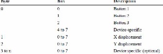
Table 2Interfacing USB mouse
4 FUTURE SCOPES FOR USB
Since USB is now dominant over other data transfer protocols, it is suffice to discuss its scope in future.
4.1 USB TO USB Synchronization
It is the concept in which research is going to make such a device that will make the data transfer without use of taking support of computer. It will make the data transfer very easy and more effectively and time reducing data transferring. Block diagram for such concept is given below.
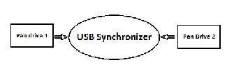
Figure 8 Block Diagram of USB Synchronizer
For this, one easy method is, synchronizer has some memory element which stores the data of 1st memory unit and then transfers the data of 2nd unit to 1st memory unit and then temporary memory to 1st unit.
Already one such device, termed as OTG Bridge Box exists, that does the same task. The figure and some details are as below:
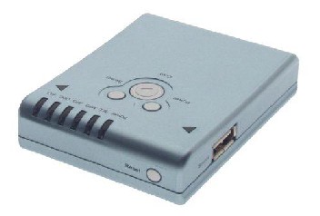
Figure 9 OTG Bridge Box
Ref. [10]
Copy/backup data from USB Pen Drive to another USB
Copy/backup data from USB Card Reader to another USB
Copy/backup data from USB Hard Disk to another USB
Copy/backup images from digital camera to another USB
Data transfer rate 400kB/sec
Support USB storage devices with FAT12/16/32file
system
Features
Functions buttons
COPY key: it will copy USB source data to USB target
Reset key: re-initial the USB devices detection
Power key: power on
Select key: select copy file
IJSER © 2013
http://www.ijser.org
International Journal of Scientific and Engineering Research, Volume 4, Issue 7, July 2013
ISSN 2229-5518
2095
LED indicators
Source (Source OK/Copy Processing/Copy OK/Error)
Target (Target OK/Copy Processing/Copy OK/Error)
Power (System Power/Power Low)
ALL (Copy all file)
MP3 (copy .mp3, .wma file)
JPG (copy .jpg file)
DOC (copy .doc, .pdf, .xls, .ppt)
AVI (copy .avi, .mov, .mpg)
In order to totally eliminate the need of peripheral device, it would be required to modify the design of USB mass storage such that it incorporates a microcontroller in itself along with a power supply mechanism .The controller will be programmed to perform a dual task of loading and storing data, two ways.
4.2 Old PS2 Mouse as decoder
As PS2 mouse are replaced by USB then old PS2 mouse can be used as decoder. As the working mentioned above, it can make the sense of mouse movement and using this sensitivity, one can make distance decoder from it. It can also be used as coordinate base system controller. It gives the exact change in coordinate change considering sign. It can be used very effectively in field of Robotics.
5 CONCLUSION
This is the review paper regarding Data Transmission protocols i.e. USB and PS2. By making them effective and by knowing their functionality, there are so many hardware and many application which can make revolution in the world of computer and applied electronics .Though PS2 is not in wide use now a days but it has its own identity and have own working theory explain above. USB is also a very effective transmission protocol due to its reliability, functionality and its independency on external power source. In near future, wide range of applications of USB, including its wireless mode for long distances, and the one without interface will be possibly the dominant ones.
[8] ”Embedded Systems” by Raj Kamal, TMH publications
Universal Serial Bus (USB): Device Class Definition
[9] For Human Interface Devices (HID) by USB Implementers’ Forum
[10] USB tutorial by ATMEL
REFERENCES
[1] KVM extension configuration including a USB-to-non-USB adapter support. PL Ferguson- US patent 6,961,798, 2005
[2] Method and apparatus for enhancing universal serial bus. J Ulenas- US patent 7,246,189
[3] Data transfer system, Switches, and Method of providing the same. C Hsueh, Y Liang- US patent. 12/142,587, 2008
[4] Extension of USB functionality through shadowing of a remote USB
host controller. PL Ferguson- US patent 6,782,443, 2004 [5] SMD098 by Jonus Thor, Lab 3.1, November 2001
[6] Simple PS2 interface by Advance Logic synthesis for Electronics
[7] PS2 keyboard and mouse interface by Prof. Stephen A. Edwards
IJSER © 2013
http://www.ijser.org