International Journal of Scientific & Engineering Research, Volume 4, Issue 7, July-2013 2033
ISSN 2229-5518
PERFORMANCE ANALYSIS OF 8X8 MIMO OFDM SYSTEM FOR VARIOUS MODULATION TEHNIQUES USING DIFFERENT FADING CHANNELS AND PAPR REDUCTION USING SLM TECHNIQUE
Anurag Sharma, Ankush Kansal
Abstract--- One of the promising technology for 4th generation wireless communication systems is MIMO OFDM systems. The combined advantages of MIMO and OFDM make very high data rate possible. In this paper a general 8x8 MIMO-OFDM system is proposed. Analysis of various modulations(ie. BPSK, QPSK) for different fading channels is portrayed. The signal detection technology used for MIMO-OFDM system is Zero-Forcing Equalization. The fading channels used are Rayleigh and Rician and there affect on BER is shown. The PAPR of the proposed system is further reduced using SLM technique. The BER v/s SNR is better for the proposed system than other systems.
The PAPR is further reduced using different roll off factors.
Keywords- MIMO, OFDM, MIMO- OFDM, PAPR, SLM, BPSK,QPSK
------- <> -------
1. INTRODUCTION
1.1 WIRELESS
Wireless is used to describe telecommunications in which electromagnetic waves carry the signal over part or the entire communication path. The term is commonly used in
the telecommunications industry to refer to telecommunications systems (e.g. radio transmitters and receivers, remote controls etc.) which use some form of energy (e.g. radio waves, acoustic energy, etc.) to transfer information without the use of wires. Wireless communication is the transfer of information between two or more points that are not connected by an electrical conductor. Some common wireless technologies use electromagnetic wireless telecommunications, such as
————————————————

• Anurag Sharma is currently pursuing masters degree program in electronics & Comm. engineering from Thapar University, Patiala, India, E-mail: anurag.sharma04966@gmail.com
• Ankush Kansal is currently Assistant Professor in Electronics & Communication Department at Thapar University, Patiala, India E-mail: akansal@thapar.edu
radio. It encompasses various types of fixed, mobile, and portable applications, including cellular telephones, personal digital assistants (PDAs), and wireless networking. Wireless can be divided into:
• Fixed wireless - The operation of wireless devices or systems in homes and offices, and in particular, equipment connected to the Internet via specialized modems
• Mobile wireless - The use of wireless devices or systems aboard motorized, moving vehicles; examples include the automotive cell phone and PCS (personal communications services)
• Portable wireless - The operation of autonomous,
battery-powered wireless devices or systems outside the office, home, or vehicle; examples include handheld cell phones and PCS units
• IR wireless - The use of devices that convey data via IR
(infrared) radiation; employed in certain limited-range communications and control systems
IJSER © 2013 http://www.ijser.org
International Journal of Scientific & Engineering Research, Volume 4, Issue 7, July-2013 2034
ISSN 2229-5518
2. MIMO
MIMO stands for Multiple input, multiple output. Use of
multiple antennas at the transmitter and receiver in wireless systems, has rapidly gained in popularity over the past decade due to its powerful performance-enhancing capabilities. This technology offers a number of benefits that help meet the challenges posed by both the impairments in the wireless channel as well as resource constraints. The MIMO solutions that enable such significant performance gains are spatial diversity, spatial multiplexing and interference reduction and avoidance, [1]. Spatial diversity is effective method for reducing the harmful effects of multipath fading. A MIMO channel with Mt transmit antennas and Mr receive antennas potentially offers MtMr independently fading links, and hence a spatial diversity order of MtMr. Multi-carrier (MC) approach is a promising technique for achieving high speed data transmissions, [2].
General discrete time model for a MIMO channel can be represented as:
on the equal time dimension. So it can achieve a multi-
dimensional signal processing, and it obtain spatial multiplexing gain and spatial diversity gain. Assuming that each antenna is independent of others.
MIMO system has three advantages, Beam forming
technology, Spatial Diversity based on space-time coding
and spatial multiplexing [3]. Space-time coding can be used to achieve high diversity gains of MIMO systems. It can reduce the symbol error probability due to channel fading and noise by joint coding of the data stream. It can also increase the redundancy of signal by joint-coding, and gain a spatial diversity of signal in the receiver. We can take advantage of the additional diversity gain to improve the reliability of communication links. And we can improve data transfer rate and spectral efficiency by using higher order modulation under the same reliability of links.
Let us suppose that the number of the transmitting
antennas is MT , transmitted signal is sj (t), j=1,…,MT , the number of the receiving antennas is MR, received signal is yi(t), i=1,…MR , then
⎡ y1 ⎤
⎢ yk ⎥
. =
⎡ h1,1
k
2,1
.
k
1,2
k
2,2
.
. . .
. . .
. . .
k
1,Mt
k
2,Mt
.
⎤ ⎡ x1 ⎤
⎥ ⎢ xk ⎥
.
the relation between the transmitted and received signal is as follows:
⎢ ⎥ ⎢
⎢ ⎥ ⎢ .
. . . .
⎥ ⎢ ⎥
. ⎥ ⎢ ⎥
k k k
. . . k k ⎦
yi(t) = ∑j=1 h(i,j)(t) * sj (t) + ni (t), i=0, 1….MR
⎣yMr ⎦
⎣hMr,1
hMr,2
hMr ,Mt ⎦ ⎣xMt
RxAnt Tx Ant

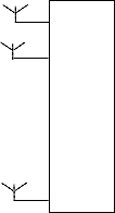


S1 h11 r1

r2
h22
.
.

hNr Nx rNr
Fig 1. MIMO Channel Model
.
Its main idea is space-time signal processing, which use
multiple antennas to increase the spatial dimension based
Where, h(i,j) (t) denotes the channel impulse response
between the transmitting antenna of number j and the
receiving antenna of number i. As the N sub-streams are
sent to the channel at the same time and each transmitted signal occupies the same frequency band, the bandwidth is not increased [4].
For a MIMO system with N transmitting antennas and M receiving antennas, it is assumed that the channel is independent Rayleigh fading channel and N, M are very large, then the channel capacity C is given by the following formula:
Where B is the signal bandwidth, ρ is the average signal to- noise of the transmitter. This formula shows that the maximum capacity of the system will increase linearly with the raise of the minimal number of antennas when the power and bandwidth are fixed.
IJSER © 2013 http://www.ijser.org
International Journal of Scientific & Engineering Research, Volume 4, Issue 7, July-2013 2035
ISSN 2229-5518
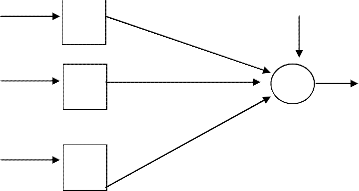
2.1 MATHEMATICAL MODEL FOR MULTI-USER MIMO SYSTEM
If we consider K independent users in the multi-user
MIMO system assuming that the Base Station(BS) and each
between BS and the u th user. In MAC, the received signal at the u th user is expressed as
DL
Mobile Station(MS) are equipped with MB and NM antennas, respectively. Let xu ∈ CNMX1 and yMAC ∈ CNBX1 (MAC stands
yu= Hu
x + zu , u= 1,2,….K
for multiple access channel) denotes the transmit signal
from the u th user, u= 1, 2,… ,K, and the received signal at the BS respectively. The channel gain between the u th user
where zu ∈ CNM X1 is the additive ZMCSCG(zero-mean
circular symmetric complex Gaussian) noise at the u th
user. Representing all user signals by a single vector, the
MS and BS is represented by HUL
∈ CNBXNM
, u = 1, 2…., K.
overall system can be represented as
DL
The received signal is expressed as
y1 H1 z1
⎡y2 ⎤
⎡ DL ⎤
⎡z2 ⎤
⎢ . ⎥
⎢H2 ⎥
⎢ . ⎥
UL x
+ HUL x
+ ⋯ + HUL x + z ⎢ ⎥
yMAC = H1 1 2 2 K K
⎢ ⎥ = x +
UL UL
x1

⎡ . ⎤
UL ⎥
⎢ . ⎥
⎢ . ⎥
⎣yK ⎦
⎣HK ⎦
⎢ . ⎥
⎢ . ⎥
⎣zK ⎦
= [H1 H2
…. HK ]⎢ . + z
⎢ . ⎥


𝑧1
x1
⎡ . ⎤
= HUL ⎢ . ⎥ + z
⎢ . ⎥
⎣xK ⎦
⎣xK ⎦

y1

DL
1 +

𝑧2
UL
1 1
x2 H2 L
z
yMAC
+


𝑥 y2
HDL
2 +
.
.
.


𝑧𝐾
HDL
. 1 + y
.
.
xK
UL
HK
Fig 2. Uplink channel model for multi-user MIMO system
where z ∈ CNBX1 is the additive noise in the receiver and it is modeled as a zero-mean circular symmetric complex
Gaussian (ZMCSCG) random vector. The downlink channel
is known as a broadcast channel (BC) in which x∈ CNBX1 is the transmit signal from the BS and yu ∈ CNBX1 is the
DL
Fig 3.Downlink channel model for multi-user MIMO system
A 4x4 MIMO system has 4 transmit antennas and 4 receiver antennas. Because of the spatial diversity the BER of a 4x4
MIMO system is less compared to lower systems. But when
we increase the number of transmitters and receivers further we get even less BER. So if we use 8x8system [5], the BER is much reduced compared to a 4x4 system.
received signal at the u th user, u = 1,2,…, K. Let Hu ∈
CNBXNM represent the channel gain
3. OFDM
IJSER © 2013 http://www.ijser.org
International Journal of Scientific & Engineering Research, Volume 4, Issue 7, July-2013 2036
ISSN 2229-5518
OFDM stands for “Orthogonal frequency division multiplexing”. At present OFDM is mostly used in digital audio broadcasting (DAB), digital video broadcasting
(DVB), Wireless LAN and MAN such as IEEE802.11a, IEEE802.11g and IEEE802.16a, HIPERLAN/2 and other high speed data application for both wireless and wired communications. It is a multicarrier modulation technique in which one single high data rate stream is divided into multiple low data rate streams and is modulated using subcarriers which are orthogonal to each other [6]. On each subcarrier channel, lower data rate brings longer symbol duration. It is advantageous to combat frequency selective fading channels, especially in wide-band applications.
It is based on multicarrier communication techniques. In multicarrier communications we divide the total signal bandwidth into number of sub carriers and information is transmitted on each of the sub carriers. In conventional multicarrier communication scheme the spectrum of each sub carrier is non-overlapping and band pass filtering is used to extract the frequency of interest, whereas in OFDM the frequency spacing between sub carriers is selected such that the sub carriers are mathematically orthogonal to each others. The subcarriers in OFDM have the minimum frequency separation required to maintain Orthogonality of their corresponding time domain waveforms, still the signal spectra corresponding to the different subcarriers overlap in frequency domain. The spectra of sub carriers overlap each other but individual sub carrier can be extracted by base band processing. This overlapping property makes OFDM more spectral efficient than the conventional multicarrier communication scheme.
This Orthogonality can be completely maintained with a small reduction in SNR, even though the signal passes through a time dispersive fading channel, by introducing a cyclic prefix (CP). OFDM requires a relatively simple equalizer at the receiver and is well suited for transmission
of high data rate applications in fading channels due to its robustness to inter-symbol interference. It is very easy to achieve accurate symbol synchronization. The nowadays
solution method of frequency selective fading of the MIMO system is to use OFDM [7]. It has quite good response, especially in indoor environments since fading caused by multipath can be combated with OFDM to improve quality of signal. Several research work has been carried out on the performance evaluation of an OFDM system both analytically and also by simulations [8].
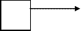
In existing wireless communications systems a user can choose between either a very high data rate or a high mobility [9]. For multimedia applications a high data rate is essential. A communications system based on OFDM seems to be suitable to provide such a high data rate even in a mobile environment [10].OFDM is also used for dedicated short-range communications (DSRC) for road side to vehicle communications and as a backbone for fourth-generation (4G) mobile wireless systems. If knowledge of the channel is available at the transmitter, then the OFDM transmitter can adapt its signalling strategy to match the channel. Combining of OFDM technology and cognitive radio technology could increase utilization of spectrum and enhance performance of Cognitive Radio system, and spectrum resource may be distributed reasonably. Different FFT sizes [11] have different impact on the BER.
Random FEC Interleaving Modulation
Data
P/S CP IFFT S/P
Channel S/P Remove FFT CP
Decoding Deinter Demod P/S
Fig 4. OFDM BLOCK DIAGRAM
4. MIMO OFDM SYSTEM
IJSER © 2013 http://www.ijser.org
International Journal of Scientific & Engineering Research, Volume 4, Issue 7, July-2013 2037
ISSN 2229-5518
Multiple input Multiple Output Orthogonal Frequency division multiplexing is a technology that uses multiple antennas to transmit and receive radio signals. MIMO- OFDM takes advantage of the multipath properties of environments using base station antennas that do not have LOS and uses both the advantages of MIMO and OFDM. The MIMO techniques [12] can handle growing demand for high speed, spectrally efficient and reliable communication. Due to increased data transmission rate, MIMO channels show frequency selectivity which degrades the system performance. To mitigate this selective fading, MIMO is combined with OFDM. MIMO-OFDM techniques are proposed for future broadband wireless systems like
4G.With the development of wireless data and multimedia applications, the demand on transmission rate and QoS assurance of wireless communication system is correspondingly rising, the OFDM and MIMO technologies are gaining more and more attention [13]. OFDM inherits the characteristics of multi-carrier parallel modulation and corresponding growth of symbol from the traditional MCM. It is very easy to achieve accurate symbol synchronization. MIMO system can use the multi-path component of the transmission to a certain extent. The nowadays solution method of frequency selective fading of the MIMO system is to use a balanced technology in general, another method is to use OFDM.
Orthogonal frequency division multiplexing (OFDM)
modulation is advantageous to combat frequency selective
fading channels, especially in wide-band applications. Multiple-input multiple-output (MIMO) techniques are effective strategies to increase spectral efficiency. Thus, the MIMO-OFDM [14], technique can be used in wireless communication systems to achieve gigabit transmission. MIMO technology will predominantly be used in broadband systems that exhibit frequency-selective fading and, therefore, inter symbol interference (ISI). OFDM
modulation turns the frequency-selective channel into a set of parallel flat fading channels and is, hence, an attractive way of coping with ISI. Advantages of MIMO OFDM
systems are very high capacity, spectral efficiency and improved communications reliability i.e., reduced bit error rate (BER) achieved at reasonable computational complexity.
MIMO OFDM technology enables high capacities suited for Internet and multimedia services, increases the range and reliability. It Increases diversity gain and enhance system capacity on a time-varying multipath fading channel improving power-spectral efficiency in wireless communication systems besides optimizing the power efficiency. This technology guarantees each user's quality of service requirements, including bit-error rate and data rate and as a result ensures fairness to all the active users. The coding over the space, time, and frequency domains provided by MIMO-OFDM enables a much more reliable and robust transmission over the harsh wireless environment. Space Time Frequency coding can achieve the maximum diversity gain in an end- to-end MIMO- OFDM system over broadband wireless channels.
In the area of Wireless communications, MIMO-OFDM is
considered as a mature and well established technology. The main advantage is that it allows transmission over highly frequency-selective channels at a reduced Bit Error Rate (BER) with high quality signal. One of the most important properties of OFDM transmissions is the robustness against multi-path delay spread. This is achieved by having a long symbol period, which minimizes the inter-symbol interference. MIMO [15], can be used either for improving the SNR or data rate. The combination of (OFDM and MIMO) is very promising when aiming at the design of very high-rate wireless mobile systems.
IJSER © 2013 http://www.ijser.org
International Journal of Scientific & Engineering Research, Volume 4, Issue 7, July-2013 2038
ISSN 2229-5518
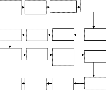
MODULATOR 1
OFDM DEMODULATOR 1
DATA SINK
DATA
SOURCE
OFDM MODULATOR 2
OFDM
DEMODULATOR 2
CHANNEL
ENCODER
MIMO . .
ENCODER . .
. .
MIMO DECODER
CHANNEL DECODER
OFDM MODULATOR 3
OFDM DEMODULATOR L
SIGNAL PROCESSING
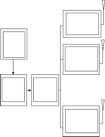
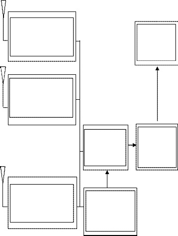
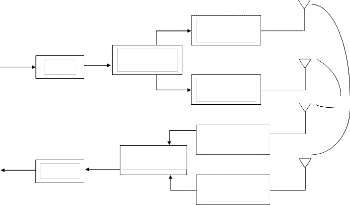
Fig 5. BLOCK DIAGRAM OF MIMO OFDM SYSTEM
4.1 MATHEMATICS
MIMO-OFDM system with 2 Transmitters and receivers is
shown in fig 6 with total number of N subcarriers. Xt is
modulated data using suitable modulation techniques for
kth subcarrier. After modulation, the mapping of
modulated data is done so that on the first and second antenna same data is transmitted and modulated OFDM
IJSER © 2013 http://www.ijser.org
International Journal of Scientific & Engineering Research, Volume 4, Issue 7, July-2013 2039
ISSN 2229-5518

symbols. Signal after inverse fast fourier transform (IFFT) at the transmitter can be written as
Tx 2
Input N Data .
Modulated data
OFDM
Modulation
Channel
Mod
.
mapping
.
.
Xk
OFDM Modulation
Rx 1
Rx 2
TRANSMITTER
Demod
Received data
N
demapping
.
.
OFDM
Demodulation
OFDM Demodulation
Channel
Output Data Z′
2
rτ (n) = {�[x′(n) ⊗ h′ (n) + w(n)]}ej[2π∆fτt+φτ(n)]
t=1
Fig 6. TX, RX MODEL OF MIMO OFDM SYSTEM
2π
τ = 1 or 2 (2)
where, ∆f τ and φτ (n) are frequency offset and phase noise.
𝜏 is received antenna. x(n), h(n), w(n), r(n) are transmitted
signal, channel impulse response, AWGN and received
N−1
t j(
)kn
signal respectively. The received signal after fast fourier

xt (n) = ∑k=0 Xk e N
for 0≤n≤N-1
transform (FFT) can be written as:
t = 1 or 2 (1)

Where, j=√−1 , t is transmitter antenna. The received signal

2π

τ = ∑N−1 rτ (n)e−j( N )kn
afflicted by phase noise and frequency offset can be
expressed as [16]:
Y
N
1 N−1
n=0
2
N−1

t t j� 2π
�(l−k+∈τ)n+φτ(n)�
= N ∑n=0 ∑t=1 ∑l=0
Xl Hl e N
+ Nk
2 N−1
t t τ
= ∑t=1 ∑l=0 Xl Hl Ql−k + Nk
(3)
Tx 1
where, Yk , Xk and Hk are the frequency domain expression
of r(n), x(n), h(n). Nk is the AWGN. ∈ is the normalized
IJSER © 2013
http://www.ijser.org
International Journal of Scientific & Engineering Research, Volume 4, Issue 7, July-2013 2040
ISSN 2229-5518
frequency offset and is given b∆fT y. T is the subcarrier
symbol period.
At receiver, OFDM symbols are demodulated and the
1 2
signal can be recovered from the relation of Zk = Yk + Yk .
τ 1 2
QL can be given by:

2π
Yk and Yk are the first antenna and the second antennas kth
subcarrier data. The innovative data can be detected
τ 1
N−1
j[�
�(L+∈τ)n+φτ(n)]
through the detection process. For ease of system
QL = N ∑n=0 e N
𝜏 𝜏
performance analysis we assume that Qτ,t
= Qτ .

= exp[j{2𝜋(𝐿 +∈𝜏 ) + 𝜑𝜏 }(1/2-1/2N)] sin[{2𝜋(𝐿+∈ )+𝜑 }/2]
𝑁.sin[{2𝜋 𝐿+∈ +𝜑 }/2𝑁]
(4)
4.2 THEORETICAL EXPRESSION
1 2 2 2
Both antennas transmit the same signal of the form of
E[|Hl | ] = E[|Hl | ] =1 and
1 2
Xl = Xl = Xk the kth subcarrier signal. The received signal
1 2 2 2 2
at the receiver 1(RX1) is
E[|𝑋𝑙 | ] = E[|𝑋𝑙 | ]= |𝑋|
(8)
N−1
1 1 1 1
N−1
2 2 1
The desired received signal is generated by the kth
Yk = � Xl . Hl . Ql−k + � Xl . Hl . Ql−k + N1k
l=0
1 1
N−1
l=0
1
1 . Q1 + X
H2 . Q1
subcarrier. Consider l=k, the received signal power is
expressed as:
2 = {E [|X |2].E[|H1 |2]. |Q1 |2 + E [|X |2]. E[|H |2]. |Q1 |2+
= Xk.Hk . Q0 + ∑l=0,l≠k Xl . Hl
l−k
k. K 0
σDRS
k k
1 2 2 2
0 k k 0
2 2 2 2 2
N−1
2 2 . Q1 + 𝑁
E[|Xk |2].E[|Hk | ]. |Q0 | +E[|Xk| ].E[|Hk | ]. |Q0 | }
+ ∑l=0,l≠k Xl . Hl
l−k
1𝑘
2 1 |2 + |X|2. |Q2 |2}
1 1 2 1
N−1
1 1 1
= 2{|X| . |Q0 0
= Xk.{Hk . Q0 + Hk . Q0 } + ∑l=0,l≠k{Xl . Hl . Ql−k+
1 2 2 2
2 2 1
= 2|X|2{|Q0 |
+ |Q0 | }
Xl . Hl . Ql−k }+ 𝑁1𝑘
1 2 2 1


2 sin((2π∈1 + 1 )/2)}2
sin((2π∈1 + 1 )/2)}2
= Xk + Xk {Hl . Ql−k } + Hk . Q0 − 1} +
= |X| [�
1 � + { 2 ]
N2 .{(2π∈1 +φ )/2N)}2
N2 .{(2π∈2 +φ )/2N}2
N−1


1 1 1 1 1
∑l=0,l≠k{Xl . Hl . Ql−k } + N1k
(5)
4{sin((2π∈1 +φ )/2)}2
4{sin((2π∈1 +φ )/2)}2
Similarly the received signal at the receiver 2(RX2) can be
= |X|2 [
(2π∈1 + 1)2 +
(2π∈2 + 2 )2 ]
given by:
2
N−1
1 1 2
N−1
2 2 2
= |X|2 [{sin((2π ∈1 + φ1 )/2)}2(34.7738) + {sin((2π ∈2 +
φ2 )/2)}2(34.7738)] (9)
Yk = �{Xl . Hl . Ql−k } + � Xl . Hl . Ql−k + N2k
As ICI is corrupted by adjacent subcarrier signal.
l=0
l=0
1 2 2 2
Considering l≠k. So, the ICI power is expressed as:
= Xk + Xk {Hk . Q0 + Hk . Q0 − 1} +
N−1
1 2 1 2
1 2 N−1 2 2
N−1
1 1 . Q2 + X1. H2 . Q2 } + N
(6)
σICI 2 = ∑l=0,l≠k E[|Xl | ].E[|Hl | ].|Ql−k|
+∑l=0,l≠k E[|Xl | ].E
∑l=0,l≠k{Xl . Hl
l−k
l 1 l−k 2k
Final signal is achieved as follows:
[|Hl 2
1 2 N−1
1 2 1 2 2 2
′ 1 2
2 | ]. |Ql−k |
+ ∑l=0,l≠k E[|Xl | ] . E[|Hl | ]. |Ql−k| +
Zk = Yk + Yk
N−1
2 2 2 2 2 2
1 1 2
2 1 2
∑l=0,l≠k E[|Xl | ] . E[|Hl | ]. |Ql−k |
= 2Xk+ Xk {Hk . (Q0 + Q0 ) + Hk . (Q0 + Q0 ) − 2}+
N−1
1 2 2 2 2
N−1
1 1 1
1 . H1 . Q2 }+ ∑N−1
{X2 . H2 . Q1
= 2∑l=1 |X|2. |Ql |
+ |X| |Ql |
∑l=0,l≠k{Xl . Hl . Ql−k + Xl l
l−k
l=0,l≠k l
l l−k +
2 2 2
Xl . Hl . Ql−k } + Nk
= 2∑N−1 |X|2. {|Q1 |2
2|2}
l=1
l + |Ql

1 2 N−1
1 2 1 1

= 2Xk + 2Xk{(Q0 + Q0 )-1}+ ∑l=0,l≠k{(Xl + Xl ). Ql−k + (Xl + 1
2 2 = 2|𝑋|2 [{sin((2𝜋 ∈1 + 𝜑1 )/2)}2 ∑𝑁−1 1 1
Xl ). Ql−k }+Nk (7)
In order to evaluate the statistical properties [17], assuming
𝑙=1 2𝜋�𝑙−𝑘+∈ �+𝜑
[𝑁𝑠𝑖𝑛 2𝑁 ]2

+ {sin((2𝜋 ∈2 + 𝜑2 )/2)}2 ∑𝑁−1 1
average channel gain
IJSER © 2013 http://www.ijser.org

2𝜋�𝑙−𝑘+∈ �+𝜑
[𝑁𝑠𝑖𝑛 ]
2𝑁
International Journal of Scientific & Engineering Research, Volume 4, Issue 7, July-2013 2041
ISSN 2229-5518
probability of PAPR larger than a threshold z can be
1 1

|X|2[{sin �2π∈ + φ �}2= (0.6704) + {sin((2𝜋 ∈2 + 𝜑2 )/
2
2)}2(0.6704)] (10)
The signal to noise ratio (SNR) can be calculated as [18]:
|𝑋|2
written as P (PAPR > z) =1-((1 − e−z ) N ) Probability of
PAPR greater than z is equals to the product of each
independent candidate’s probability and can be written as
P {PAPRlow > 𝑧} =(P{PAPR > 𝑧})M= ((1 − exp(−z))N )M
SNR =
𝜎𝑛 2

(11)
First M statistically independent sequences which represent
The signal to noise plus interference ratio (SNIR) of MIMO
OFDM can be calculated as:
𝜎𝐷𝑅𝑆 2
the same information are generated then resulting M
statistically independent data blocks
SNIR =


𝜎𝐷𝑅𝑆 2
𝜎𝑛2 +𝜎𝐼𝐶𝐼 2

𝜎𝑛2

= 1 𝜎𝐼𝐶𝐼2
𝜎𝑛2
Sm=[Sm,0, Sm,1 , … Sm,N−1 ]T, 𝑚=1, 2,…, M are forwarded into
IFFT. Finally, at the receiving end, OFDM symbols
𝑇
2𝜋∈1+ 𝜑1 2
2 2 2
𝑥𝑚 =[𝑥1 , 𝑥2 , … 𝑥𝑁 ]
in discrete time-domain are acquired, and
= SNR.[

SNR.[�sin�

2 �� (34.7738)+{sin((2𝜋∈ + 𝜑 )/2)} (34.7738)
2𝜋∈1+ 𝜑1 2
then the PAPR of these M vectors are calculated separately.
(12)

1+SNR.[�sin�
2 �� (0.6704)+{sin((2𝜋∈2+ 𝜑2)/2)}2(0.6704)
The sequences 𝑥𝑑 with the smallest PAPR will be elected for
final serial transmission. Assuming that for a single OFDM
Probability of error is given by: P =1/2 erfc(sqrt(SNIR) )
5. PAPR
PAPR[19] is the ratio between the maximum power and the
symbol, the CCDF probability of PAPR larger than a
threshold is equals to p. The general probability of PAPR
larger than a threshold for k OFDM symbols can be
expressed as pk .The new probability obtained by SLM
algorithm is much smaller compared to the former. Data
blocks Smare obtained by multiplying the original sequence with M uncorrelated sequence Pm.Different pseudo-random sequences Pm = [Pm,0 , Pm,1, … Pm,N−1 ]𝑇 , 𝑚=1,2,…,M, where
jφm,n
average power of the complex pass band signal 𝑥𝑛, that is,
Pm,n = e
and stands for the rotation factor. 𝜑𝑚,𝑛 is

Ppeak

max[|xn |2 ]
uniformly distributed in [0 2π]. The N different sub-carriers
are modulated with these vectors respectively so as to
PAPR = Pavg = 10log
E[|xn |2 ]
generate candidate OFDM signals. All the elements of
where, Ppeak is the peak output power
Pavg is the average output power
E[. ] denotes the expected value
𝑥𝑛 represents the transmitted OFDM signals which are
obtained by taking IFFT operation on modulated input
symbols XK. Mathematical, xn is expressed as:
phase sequence P1 are set to 1 so as to make this branch
sequence the original signal. The symbols in branch m is
expressed as 𝑆𝑚 =[𝑋0 𝑃𝑚,0, 𝑋1 𝑃𝑚,1 , . . 𝑋𝑁−1 𝑃𝑚,𝑁−1 ]𝑇 , 𝑚=1,2,…,𝑀
and then transfer these M OFDM frames from frequency
domain to time domain by performing IFFT calculation.
The entire process is given by 𝑥𝑚 (𝑡) = ∑N−1 Xn Pm,n. ej2πn∆ft,

1 √N 0
xn = ∑N−1 Xk Wnk
𝑚=1,2,…𝑀. Finally, the one which possess the smallest

√N k=0 N
For an OFDM system with N sub-carriers, the peak power
of received signals is N times the average power when phase values are the same. The PAPR of baseband signal will reach its theoretical maximum at PAPR (dB) =10log N.
5.1 PAPR reduction using SLM Technique
This technique uses signal scrambling Technique. The fundamental principle of this technique is to scramble each OFDM signal with different scrambling sequences and select one which has the smallest PAPR value for transmission. This can reduce the appearance probability of high PAPR to a great extent. SLM[20] method applies scrambling rotation to all sub-carriers independently. This method can be applied to any scenario without restriction on the number of sub-carriers and type of modulation. The
PAPR value is selected for transmission. Its mathematical
expression is given as xd= argmin1≤m≤M(𝑃𝐴𝑃𝑅(xm )) where argmin(⋅) represent the argument of its value is minimized.
At the receiver, the whole sequence of branch number m as
side information transmitted to the receiving end is selected. It can be realized by sending the route number of the vector sequence. This is only possible when the receiving end is able to restore the random phase sequence
Pm by means of look-up table or any other method. Since
the side information plays a vital role for signal restoration
at the receiver, channel coding is used to guarantee a
reliable transmission. Once channel coding technique is adopted during the data transmission process, sending of any additional side information is not required. In this way, all possible routes are detected at the receiving end from which the most likely one is chosen as the optimum.
5.2 Advantages of SLM Technique
IJSER © 2013 http://www.ijser.org
International Journal of Scientific & Engineering Research, Volume 4, Issue 7, July-2013 2042
ISSN 2229-5518
-2
10
1. SLM algorithm can be used for different OFDM systems
with different number of carriers. It is particularly suitable
for the OFDM system with a large number of sub-carriers.
4tx-4rx simulation
-3
10
2. This technique can improve the PAPR distribution of
OFDM system, that is, significantly reduce the presenting
probability of large peak power signal.
-4
10
-5
10
0 5 10 15 20 25
Eb/N0, dB
6. SIMULATION AND RESULTS
Fig7(c) BER v/s SNR plot for 2x2 MIMO OFDM
using BPSK modulation for Rayleigh fading channel
2tx-2rx simulation
-2
10
It is shown that BER of 8x8 configuration is best of all other
configurations used. The FFT size of 128 is used. The spatial diversity of the 8x8 system makes it the strongest contender for low BER.. SNR v/s BER plot for different modulations
and different channels is shown. Here different antenna 10
configurations viz 2x2, 4x4 and 8x8 are used. The analysis
is done for two channels Rayleigh and Rician.
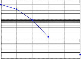
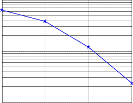
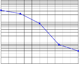
6.1 BER v/s SNR for 8x8,4x4 and 2x2 configuration using BPSK modulation in Rayleigh fading channel
Fig7(a) BER v/s SNR plot for 8x8 MIMO OFDM
using BPSK modulation for Rayleigh fading channel
8tx-8rx simulation
-2
10
-4
10
0 5 10 15
Eb/N0, dB
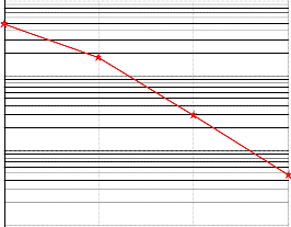
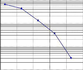
6.2 BER v/s SNR for 8x8,4x4 and 2x2 configuration using QPSK modulation in Rayleigh fading channel
Fig7(d) BER v/s SNR plot for 8x8 MIMO OFDM
using QPSK modulation for Rayleigh fading channel
-3
10
-4
10
-5
10
0 5 10 15
Eb/N0, dB
Fig7(b) BER v/s SNR plot for 4x4 MIMO OFDM
using BPSK modulation for Rayleigh fading channel
IJSER © 2013 http://www.ijser.org
International Journal of Scientific & Engineering Research, Volume 4, Issue 7, July-2013 2043
ISSN 2229-5518
BER v/s SNR
-2
10
2tx-2rx simulation
-2
10
-3 -3
10 10
-4 -4
10 10
-5
10
0 2 4 6 8 10 12 14 16 18 20
Eb/N0, dB
-5
10
0 2 4 6 8 10 12 14 16 18 20
Eb/N0, dB
Figure 7 (a)-(f): SNR v/s BER plots for BPSK,QPSK over Rayleigh channel for MIMO-OFDM system employing different antenna configurations.
The curves show that in MIMO-OFDM system as we increase the no. of Transmitters and Recievers the BER keeps on decreasing because of space diversity and the proposed system provide better BER performance as
compared to the other antenna configurations used.
Fig7(e) BER v/s SNR plot for 4x4 MIMO OFDM
using QPSK modulation for Rayleigh fading channel
4tx-4rx simulation
-2
10
Table 1: SNR improvement for BPSK, QPSK in Rayleigh channel by using 8 X 8 antenna configuration over 4 X 4 antenna configuration
-3
10
In Table 1 the advantage of using higher order (8 X 8)
10-4 antenna configuration over lower order (4 X 4) antenna configuration is shown in the form of SNR gain in dB for BPSK. As, we go on to higher order antenna configuration
the BER will keeps on decreasing. For M-QAM with the
-5
10
0 2 4 6 8 10 12 14 16 18 20
Eb/N0, dB
Fig7(f) BER v/s SNR plot for 2x2 MIMO OFDM
using QPSK modulation for Rayleigh fading channel
increase in the level of the modulation the BER will also increase. The solution for this is to increase the SNR values for higher level modulations.
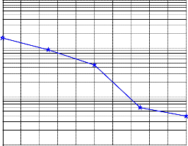
6.3 BER v/s SNR for 8x8,4x4 and 2x2 configuration using BPSK modulation in Rician fading channel
IJSER © 2013 http://www.ijser.org
International Journal of Scientific & Engineering Research, Volume 4, Issue 7, July-2013 2044
ISSN 2229-5518
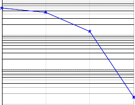
Fig8(a) BER v/s SNR plot for 8x8 MIMO OFDM
using BPSK modulation for Rician fading channel
Fig8(c) BER v/s SNR plot for 2x2 MIMO OFDM
using BPSK modulation for Rician fading channel
8tx-8rx simulation
-2
10
BER v/s SNR curve
-2
10
-3
10 -3
10
-4
10
-5
10
-5 0 5 10 15 20
Eb/N0, dB
-4
10
-4 -2 0 2 4 6 8 10 12
Eb/N0, dB
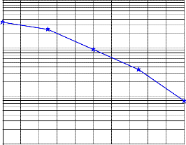
6.4 BER v/s SNR for 8x8, 4x4 and 2x2 configuration using QPSK modulation in Rician fading channel
Fig8(b) BER v/s SNR plot for 4x4 MIMO OFDM
using BPSK modulation for Rician fading channel
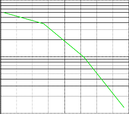
Fig8(d) BER v/s SNR plot for 8x8 MIMO OFDM
using QPSK modulation for Rician fading channel
4tx-4rx simulation
-2

10
8x8 simulation
-2
10
-3
10
-3
10
-4
10
-4
10
-5
10
0 2 4 6 8 10 12 14 16 18 20
Eb/N0, dB
-5
10
0 5 10 15
Eb/N0, dB
Fig8(e) BER v/s SNR plot for 4x4 MIMO OFDM
using QPSK modulation for Rician fading channel
IJSER © 2013 http://www.ijser.org
International Journal of Scientific & Engineering Research, Volume 4, Issue 7, July-2013 2045
ISSN 2229-5518
BER v/s SNR
-2
10
-3
10
-4
10
-5
10
0 2 4 6 8 10 12 14 16 18 20
Eb/N0, dB
Figure 8 (a)-(e): SNR v/s BER plots for BPSK,QPSK over Rician channel for MIMO-OFDM system employing different antenna configurations.
Table 2
Modulation used | SNR improvement for Rician channel (dB) |
BPSK | 4 dB |
QPSK | 6.4 dB |
0
10
6.5 PAPR reduction using Selected mapping
Technique
-1
10
Orignal
Beta=0.2
Beta=0.4
Beta=0.8
Beta=1.6
-2
10
-3
10
5 6 7 8 9 10 11 12
PAPR0 [dB]
IJSER © 2013 http://www.ijser.org
International Journal of Scientific & Engineering Research, Volume 4, Issue 7, July-2013 2046
ISSN 2229-5518
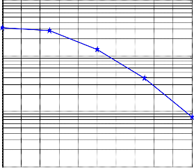
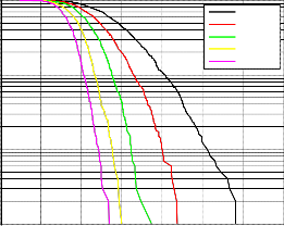
Fig 9 PAPR of 8x8 MIMO OFDM system
Fig 9 shows the PAPR of the proposed system. We can see that the PAPR of the original system is shown in black colour and it is 10.8 dB. By using SLM technique the PAPR is reduced. PAPR values for different roll off factors is also shown. We conclude that as the roll off factor is increased the PAPR starts reducing. With a beta value of 1.6 the PAPR is reduced to a value 7.5 dB. So there is an improvement of 3.3 dB in PAPR. The black curve shows the original PAPR, red shows PAPR with beta=0.2, green curve shows PAPR with beta=0.4, yellow with beta= 1.4, pink
7. CONCLUSION
In this paper performance analysis of MIMO OFDM system for different modulation techniques using different fading with beta=1.6.
8. REFERENCES

[1] Dhawan S, “Analogy of Promising Wireless Technologies on Different Frequencies: Bluetooth, WiFi, and WiMAX”, Wireless Broadband and Ultra Wideband Communications, pp 14,27-30, 2007.
[2] Zeyu Zheng; Jianping Wang, International Conference on Communications, “Indoor and Mobile radio communication”, pp 1-6, 2009.
channels is presented. Different Antenna configurations are used. The most important advantage of MIMO OFDM system is data capacity which can be further enhanced by using higher order modulations. The major obstacle in this regard is BER (bit error rate) with the order of the modulation. The panacea for this is to increase the SNR which results in reduction of distortions introduced by the channel, and the BER will also decreases at higher values of the SNR for higher order modulations.
As the number of transmitters and receivers increase, the space diversity increases. So an 8x8 antenna configuration will lower the BER at given SNR as compared to lower
order Antenna configuration (2x2, 4x4). High data capacity at a given value of SNR can be achieved. The performance
of the proposed system is better in terms of SNR as
compared to systems with lower antenna configuration
(4x4, 2x2). One of the problems associated with OFDM systems is PAPR. The PAPR of the proposed system is reduced using SLM technique.
[3] Jindal, S, “Grouping WI-MAX, 3G and WI-FI for wireless broadband”, IEEE and IFIP International Conference in Central Asia, pp 510-723, 2005.
[4] Zahmati, “Emerging wireless applications in aerospace: Benefits, challenges, and existing methods”, Fly by Wireless Workshop (FBW), pp 1-4, 2011.
IJSER © 2013 http://www.ijser.org
International Journal of Scientific & Engineering Research, Volume 4, Issue 7, July-2013 2047
ISSN 2229-5518
[5] S. Alamouti, “A simple transmit diversity technique for wireless communications,” IEEE Journal on Selected Areas Communication., vol. 16, no. 8, pp. 1451–1458, October 1998.
[6] H. El Gamal and A. R. Hammons, “On the design of algebraic space time codes for MIMO block-fading channels,” IEEE Transaction on Information Theory, vol. 49, no. 1, pp. 151–
163, 2003.
[7] P. Rabiei, W. Namgoong and N. Al-Dhahir, “Frequency domain joint channel and phase noise estimation in OFDM WLAN systems,” In Proceeding of Asilomar Conference on Signals, Systems and Computers, pp. 928–932, (Pacific Grove, CA),October 2008.
[8] S.Thoen, L. V. Perre, and B. Gyselinckx. “Performance analysis of combined transmit-SC/receive-MRC,” IEEE Transaction Communication, vol.49,no.1, pp.5–8, Aug, 2001.
[9] L. J. Cimini and Jr., “Analysis and simulation of a digital mobile channel using orthogonal frequency division multiplexing,” IEEE Transactions On Communication, vol.
33,pp. 665-675, 1985.
[10] C.Gómez-Calero, L. García-García, L. de Haro-Ariet, “New Test-bed for Evaluation of Antenna and System Performance for MIMO Systems.” European Conference on Antennas and Propagation 2007.
[11] Steendam, H., Moeneclaey, M., “Analysis and Optimization of the performance of OFDM on Frequency-Selective Time- Selective Fading Channels”, IEEE Transactions on Communication, Vol-47, No.12 December 1999.
[12] S.B.Weinstein and P.M. Ebert, “Data transmission by frequency-division multiplexing using the discrete fourier transform,” IEEE Transactions on Communication Technology, vol. 19, no. 5, pp. 628–634, 1971.
[13] Shao Lulu, “Research on Application of OFDM Technology in Cooperative Spectrum Sensing”, International Conference on advanced communication Technology ,pp 741-744, 2009.
[14] P.Malathi, “Improved Interleaving Technique for PAPR Reduction in OFDM-MIMO System”, Second Asia International Conference on Modelling & Simulation,pp 253-
258,2008.
[15] Mohammad Mohammadnia-Avval, “Error-Rate Analysis for Bit-Loaded Coded MIMO-OFDM”, IEEE Transactions on vehicular Technology, vol. 59, no. 5, pp 2340-2351, June 2010.
[16] Y.-S. Li, H.-G. Ryu, J.-W. Li, D.-y' Sun, H.-y' Liu, L. -1. Zhou,
& Y. Wu, “ICI compensation in MISO-OFDM system affected by frequency offset and phase noise,” Wireless Communication Networking and Mobile Computing ( WiCOM '08), vol. 5, no.12,pp. 32-38,2008.
[17] Yin Wang; Zhiyu Huang, “Error probability analysis of OFDM systems with ICI self-cancellation over AWGN and Rayleigh flat-fading channels," Communications, 2009. APCC 2009.
15th Asia-Pacific Conference on , vol., no., pp.798,802, 8-10
Oct. 2009
[18] V. Gupta, S. Chaudhary and A. Jain, “Bit error rate analysis for OFDM systems for MRC receivers in Nakagami-m fading channel generated by using Rayleigh and Ricean fading, " International Journal of Computer Applications, vol. 1, no. 29, pp.88-94,2010.
[19] Tao Jiang; Yiyan Wu, “An Overview: Peak-to-Average Power Ratio Reduction Techniques for OFDM Signals”, IEEE Transactions on Broadcasting , vol.54, no.2, pp.257,268, June
2008
[20] Bauml, R.W, Fischer, R.F.H and Huber, J.B, “Reducing the peak-to-average power ratio of multicarrier modulation by selected mapping”, IEEE Electronic Letters, vol. 32, no. 22, pp.2056-2057, Oct 1996.
IJSER © 2013 http://www.ijser.org