𝑚𝑎𝑥|𝑥𝑖 |2
𝑃𝐴𝑃𝑅𝑂𝐹𝐷𝑀 = 1 𝑁 −1
∑ 𝑐 |𝑥 |2
, 𝑓𝑜𝑟 𝑖
International Journal of Scientific & Engineering Research, Volume 4, Issue 12, December-2013 1671
ISSN 2229-5518
Overview of Nonlinear Distortion in OFDM Systems
Lokesh C. 1, Dr. Nataraj K. R.2, Dr. Rekha K. R 3, Mamatha C. G. 4
1 Assistant Professor,Department of E & E E,VVCE,Mysore, India.
2 & 3 Professor, Department of E & C E ,SJBIT, Bangalore, India. 4 Assistant Professor, Dept of E & EE, GSSSIETW, Mysore, India.
Email: 1 lokeshnanjaiah@gmail.com, 2 nataraj.sjbit@gmail.com, 4 mamathacg10@gmail.com.
Abstract - OFDM is to be a very effective technique for high speed digital communications in environments affected by high interference and multipath propagation. However, the principle of OFDM that brings
I. INTRODUCTION
The PAPR is defined as:![]()
𝑚𝑎𝑥|𝑥𝑖 |2
𝑃𝐴𝑃𝑅𝑂𝐹𝐷𝑀 = 1 𝑁 −1
∑ 𝑐 |𝑥 |2
, 𝑓𝑜𝑟 𝑖
𝑁𝑐
𝑖=0 𝑖
= 0,1,2, … . . , 𝑁𝑐 − 1
Index Terms – Peak-to-Average Power Ratio (PAPR), Power Amplifiers (PA), High Power Amplifiers (HPA), Traveling-Wave Tube Amplifiers (TWTA), Soft Envelope Limiter (SEL), Solid State Power Amplifiers(SSPA), Power Amplifier Nonlinearity Cancellation (PANC), Output Back Off (OBO), High Power Amplifier (HPA).
Where xi are the transmitted time samples of
an OFDM symbol. Nonlinear distortions are
mainly caused by the Power Amplifiers (PA). The nonlinear distortion at the transmitter causes interference both inside and outside the signal bandwidth. The in-band component affects the system BER [8] while the out-of band component affects adjacent frequency bands [2].
The high PAPR in OFDM systems brings an additional condition in order to maintain their performance in an acceptable range. The nonlinear distortions have to be kept as low as possible. A linear behavior is achieved when operating the amplifier sufficiently below its saturation point. As a result, a high output back off (OBO) is required in the power amplifiers. The OBO is the ratio between the saturation power and the actual output power, which is the power at which the amplifier is operating [3].
IJSER © 2013 http://www.ijser.org
International Journal of Scientific & Engineering Research, Volume 4, Issue 12, December-2013 1672
ISSN 2229-5518
This can be expressed as![]()
𝑃𝑠𝑎𝑡
2
![]()
𝑠𝑎𝑡
The modulated IF carrier is then
𝑂𝐵𝑂 =
𝑃𝑜𝑢𝑡
= 𝐸{|𝑦(𝑡)|2}
converted to the RF carrier frequency via the
baseband converter. The baseband converter is
Where Vsat is the saturation voltage and y(t) is the output of the amplifier. Generally High Power Amplifiers (HPA) show better power efficiency when driven close to their saturation point. Therefore, a higher OBO results in lower power efficiency. Power efficiency is especially valuable in the cases, for example, of portable devices (mobile phones) and satellite systems, where power is indeed a very limited and expensive resource. Therefore a preliminary study of the system is required for finding a good trade-off between transmitted power and degradation [4].
II. THE OFDM RF SUB-SYSTEM
built up of a multiplier and a local oscillator of frequency fc which is the carrier frequency or central frequency. The output of the baseband converter is then filtered by the spectral filter to limit the bandwidth of the RF carrier. This filtered signal is then amplified by the PA to an adequate power level for the RF transmission [6].
The amplifier introduces most of the nonlinear distortion in the system and therefore it is the main element to be analyzed in this paper. The following section describes the characteristics and models of power amplifiers used in OFDM systems.
IJSER
The Power Amplifier is part of the RF sub- system of OFDM systems. The RF sub-system consists of the In-phase and Quadrature (IQ) modulator, a baseband converter, a spectral filter and the power amplifier. Figure 1 shows a block diagram of an RF sub-system [5].
III. POWER AMPLIFIERS IN OFDM
APPLICATIONS
Ideally, a power amplifier produces a scaled version of the input signal. Therefore, the output an ideal amplifier can be described as
𝑉𝑜𝑢𝑡 = 𝐺𝑉𝑖𝑛
RF Sub
System

Where G is the voltage gain of the amplifier. The output signal has the same waveform as the input signal and no new frequencies are introduced [7].
A However, real amplifiers do not behave in this way. They act on the signal in an uneven way depending on the magnitude and frequency
Figure 1: Block diagram of the RF Sub System.![]()
The IQ modulator splits the input data stream into two separate streams xI and xQ . Then it multiplies these streams by a sine and a cosine waveforms respectively. The resulting signals are later summed together to form a modulated intermediate frequency (IF) carrier. The envelope of the IF carrier A is given by:
of the signal. This results in a distortion of the waveform that does not follow the superposition principle and therefore is not linear.
𝑓(𝐶𝑥1) = 𝐶(𝑓(𝑥1))
𝑓(𝑥1 + 𝑥2) = 𝑓(𝑥1) + 𝑓(𝑥2)
Nonlinearities in amplifiers can be
described by their amplitude transfer characteristics - also referred as Amplitude
𝐴 = �𝑥2
+ 𝑥 2
Modulation/Amplitude Modulation (AM/AM)
conversion - and phase transfer characteristics
IJSER © 2013 http://www.ijser.org
International Journal of Scientific & Engineering Research, Volume 4, Issue 12, December-2013 1673
ISSN 2229-5518
or Amplitude Modulation/Phase Modulation
(AM/PM) conversion. The AM/AM conversion
(FA[𝜌]) describes the amplitude of the output signal for a given input amplitude (𝜌) and the AM/PM conversion (FA[𝜌]) describes the phase of the output for a given input amplitude (𝜌)[8].
Both AM/AM conversion and AM/PM conversion can either depend on the frequency at which the amplifier is operating or be the same for all frequencies. Therefore, amplifiers can be classified, in terms of nonlinearity, into frequency-dependent and frequency- independent [10]. Frequency independent amplifiers can either be memory less system or systems with memory. Frequency-dependent amplifiers are systems with memory.
In table 1 a summary of the classification and different distortion effects of nonlinear
amplifiers is presented.
deeper discussion about amplifier nonlinearities is available in [11].
IV. HIGH POWER AMPLIFIERS
Today, the most commonly used devices are the ones based on electron beam tubes, usually Travelling Wave Tube Amplifiers (TWTA), and the Solid State Power Amplifiers (SSPA) as shown in table 3.2, for different microwave bandwidths.
TWTA operation is based on the same principle of the incandescent electric light bulb: making an electric current flow through a glass tube surrounding a vacuum.
An electron emitter, which mainly consists of a heater, a cathode and an anode, starts the stream of electrons by heating the cathode. The stream passes through the anode
IJSEand travels Rthrough the helix. At this point the
In a memory less system there are no
energy storing components, and any change in the input occurs instantaneously at the output. In other words, the output and the input are in- phase and there is only AM/AM conversion. In a system with memory there are energy storing devices, therefore the output depends on the previous inputs values. This results in phase distortion in addition to the amplitude distortion.
energy is transferred to the signal travelling
around the helix thus amplifying it. Because of
their construction, TWTAs offer large currents and therefore, high output powers can be obtained [13].
TWTAs can be modeled, for the non-frequency selective case, using the model proposed by
Saleh in [12] as:
Detailed information about nonlinearities with and without memory are presented in [9] and
[10].
𝐹𝐴[𝜌] =![]()
𝑣𝜌
1 + 𝛽𝑎 𝜌2
𝛼𝑝 𝜌2
𝐹𝑃 [𝜌] =
1 + 𝛽𝑝![]()
𝜌2
For the analysis of nonlinear distortion
in OFDM systems, amplifiers are often
considered frequency-independent. In addition, even considering that in general the overall system is considered to have memory1, there is no ISI between OFDM symbols. Furthermore, in [12] the analysis is performed for Traveling- Wave Tube Amplifiers (TWTA) and solid-state power amplifiers (SSPA). In addition, [11] uses the Soft Envelope Limiter (SEL). An overview of the models for these amplifiers is presented below. Models for other amplifiers as well as a
FA[𝜌] and FP [𝜌] are the AM/AM and AM/PM
conversion functions respectively, v is the
small-signal gain of the amplifier, 𝛽R a depends on the input saturation voltage and 𝛼R p and 𝛽R p
depend on the maximum phase displacement
that can be introduced by the amplifier.
V. CHARACTERISATION OF NONLINEAR
EFFECTS IN OFDM SYSTEMS
The distortions caused by nonlinearities can be classified into two components: the in-
IJSER © 2013 http://www.ijser.org
International Journal of Scientific & Engineering Research, Volume 4, Issue 12, December-2013 1674
ISSN 2229-5518
band component and the out-of-band component. The last causes mainly adjacent- channel interference (ACI) [9] affecting other systems in adjacent bands but has no effects on the performance of the actual system. The in- band component, on the other hand, affects the performance of the system.
The effects of these distortions are:
• Interference between the in-phase and quadrature (I/Q) components due to AM/PM conversion (if present).
• Intermodulation effects on the sub-carriers.
• Wrapping of the signal constellation in each sub-channel.
process for several times, a better estimation of the received signal is achieved.
Figure 3 presents a block diagram of the PANC. An IFFT is applied to the decoded symbols and then passed through the amplifier model. The input of the amplifier is then subtracted from the output to obtain an estimation of the NLD noise term. The result is then transformed to the frequency domain by the FFT block and subtracted from the received signal. Since the distortion term is subtracted in the frequency domain, this is equivalent to a symbol-by-symbol subtraction.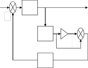
Degradation in the performance of a communication system generally results in an Y increase in the BER. The following analysis
explains, quantitatively, the impact of the -
Decision X
nonlinearities in the BIER. JSER
i(t)
Nonlinear Amplifier
d(t)
K(t)
u(t)

-
D
IFFT
Figure 2: Alternative model of a nonlinear amplifier.
VI. POWER AMPLIFIER NONLINEARITY
CANCELLATION
Power Amplifier Nonlinearity Cancellation (PANC) is introduced in [13]. This technique attacks the nonlinearity problem from the receiver point of view. It requires the knowledge of the channel coefficients and the characteristics of the amplifier.
The main idea of this technique is, based on the
received symbols, to estimate the NLD noise term caused by the amplifier and subtract it from the received signal. By repeating this
Figure 3: Power Amplifier Nonlinearity
Cancellation (PANC).
IJSER © 2013 http://www.ijser.org
International Journal of Scientific & Engineering Research, Volume 4, Issue 12, December-2013 1675
ISSN 2229-5518
VII. RESULTS
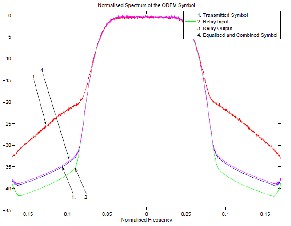
a. Different Spectra of the OFDM symbol
Non Linear Distortion (NLD) affects the spectrum of the OFDM symbol.
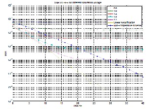
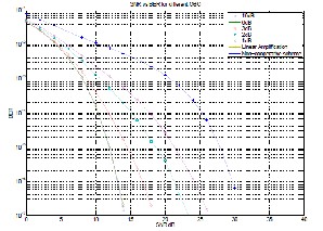
c. BER for different levels of Saturation
Voltage
Increase in BER even for large values of saturation voltage results in isolate the cause of such distortion.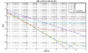
IJSER
b. BER for different levels of Output Back
Off (OBO).
Increasing the OBO results in an inefficient use of resources because the High Power Amplifier (HPA) s’ maximum efficiency is achieved when they are operating close to their saturation point.
d. BER for different OBO with optimised
MRC and Slow Fading Channel.
Slow fading channel, using 512 OFDM symbols as training sequence. The Doppler spread of the channel is fd ≈ 10 Hz.
VIII. CONCLUSION
In this paper, nonlinear amplifier distortion in OFDM systems is described. The OFDM RF sub-system is described. The characteristics and models of the most common power amplifiers used in telecommunications are also briefly introduced. A method for characterization of the NLD effects as well as a
IJSER © 2013 http://www.ijser.org
International Journal of Scientific & Engineering Research, Volume 4, Issue 12, December-2013 1676
ISSN 2229-5518
method for performance evaluation is explained. Finally, some techniques for mitigating the effects of NLD are briefly presented.
OFDM systems are highly sensitive to
NLD because of the high PAPR inherent to this modulation technique. Unfortunately, HPAs are more efficient when operated close to their saturation point, where the nonlinearities increase. The NLD term can be modeled as an additive Gaussian noise in the system. Several techniques exist for mitigating the effects of NLD noise; specifically PANC technique can be applied at the receiver in cases where other techniques are not available at the transmitter [13].
IX. REFERENCES
[1] L. Ding, “Digital predistortion of power amplifiers for wireless applications,” Engineering, Georgia Institute of Technology,
amplifier distortion in SDMA-OFDM systems,” in Proc. IEEE Int. Conf. Acoust., Speech, Signal Process., ICASSP 2006, May 2006.
[7] E. V. del Meulen, “Three-terminal
communication channels,” Adv. Appl. Prob- ability, vol. 3, pp. 120 – 154, 1971.
[8] T. Cover and A. Gamal, “Capacity theorems for the relay channel,” Information Theory, IEEE
Transactions on, vol. 25, no. 5, pp. 572 – 584, September 1979.
[9] J. N. Laneman and G. W. Wornell, “Energy- efficient antenna sharing and relaying for
wireless networks,” in IEEE WCNC, September
2000, pp. 7–12.
[10] A. Sendonaris, E. Erkip, and B. Aazhang, “Increasing uplink capacity via user cooperation diversity,” in Proc. IEEE ISIT, vol. 51, no. 11, August 1998, p. 156.
[11]A Gamal, “User cooperation diversity. part i and ii,” Communications, IEEE Trans- actions
Mar. 2004.
IJSEon, vol. 51, Rno. 11, pp. 1927 – 1938, November
[2] E. Aschbacher, “Digital predistortion of
microwave power amplifiers,” Ph.D.
dissertation, Technishe Universitat Wien, Mar.
2004.
[3] S. H. Muller and J. B. Huber, “OFDM with reduced peak-to-average power ratio by optimum combination of partial transmit sequences,” IEEE Electronics Lett., vol. 33, no.
5, pp. 368 – 369, Feb. 1997.
[4] X. Li and L. Cimini, “Effects of clipping and
filtering on the performance of OFDM,” in
Proceedings IEEE VTC97, 1997, pp. 1634–
1638.
[5] R. Baümi, R. Fischer, and J. Hüber, “Reducing
peak-to-average power ratio of multicarrier modulation by selective mapping,” IEEE Electronic Letters, vol. 30, no. 22, October
1996.
[6] F. Gregorio, T. Laakso, and J. Cousseau, “Receiver cancellation of nonlinear power
2003.
[12] A. Nosratinia, T. Hunter, and A. Hedayat, “Cooperative communication in wireless networks,” Communications Magazine, IEEE, vol. 42, no. 10, pp. 74– 80, October 2004.
[13] L. Lai, K. Liu, and H. E. Gamal, “The three- nodewireless network: Achievable rates and cooperation strategies,” IEEE Trans. Info. Theory, vol. 52, no. 3, pp. 805–828, March
2006.
Frequency-Independent System | Frequency-Dependent System |
Memory less systems – gain distortion | System with memory Frequency dependent gain distortion Frequency dependent phase distortion |
System with memory gain distortion phase distortion | System with memory Frequency dependent gain distortion Frequency dependent phase distortion |
Table 1: Classification of distortion effect in Nonlinear Amplifiers.
IJSER © 2013 http://www.ijser.org