International Journal of Scientific & Engineering Research Volume 2, Issue 6, June-2011 1
ISSN 2229-5518
Optimizing Performance of Token Ring for Bal- anced and Unbalanced Load Using OPNET Pankaj Rakheja, Dilpreet Kaur
—————————— • ——————————
oken Ring [1-6] is a Local Area Network (LAN) proto- col defined in the IEEE 802.5 section. Here all stations are connected in a ring and each station can just directly
hear the transmissions only from its immediate neighbour. Permission to transmit is granted by a message or packet called token that circulates around the ring.
Token Ring as defined in IEEE 802.5 has originated from the IBM Token Ring LAN technologies. Both are based on the token passing technologies. They differ in minor ways; so are generally compatible with each other.
Token-passing networks move a small frame, called a to- ken, around the network. Possession of the token grants the right to transmit. If a node receiving the token has no infor- mation to send, it seizes the token, alters 1 bit of the token (which turns the token into a start-of-frame sequence), ap- pends the information that it wants to transmit, and sends this information to the next station on the ring. While the information frame is circling on the ring, no token is on the network, which means that the other stations wanting to transmit must wait. Therefore, collisions cannot occur on token ring networks and prioritization of nodes is done to avoid conflicts and impermissible delays for real time appli- cations.
————————————————
• Dilpreet Kaur, is currently pursuing masters degree program in electronics and communication engineering at Institute of Technology and Manage- ment, Gurgaon, Haryana, India E-mail: er.dilpreetkaur@gmail.com
• Pankaj Rakheja, is currently pursuing masters degree program in electron- ics and communication engineering at Institute of Technology and Man-
agement, Gurgaon, Haryana, India E-mail: rakheja.prince13@gmail.com
The information frame circulates on the ring until it reaches the intended destination station, which copies the information for further processing. The information frame continues to circle the ring and is finally removed when it reaches the sending station. The sending station can check the returning frame to see whether the frame was seen and subsequently copied by the destination.
There is a monitor or head node which supervises the network. It captures the failed or erroneous packets circulat- ing in the ring to prevent unavailability of the network to the stations in case a packet rotates there indefinitely when des- tination node fails.
Unlike Ethernet CSMA/CD networks, token-passing net- works are deterministic, which means that it is possible to calculate the maximum time that will pass before any end station will be capable of transmitting. This feature and sev- eral reliability features make Token Ring networks ideal for applications in which delay must be predictable and robust network operation is important.
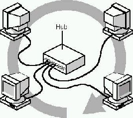
A Token Ring network is an implementation of IEEE standard 802.5. It’s not their physical cable layout that dis- tinguishes it from other networks but rather its token access method. The architecture of a typical Token Ring network begins with a physical ring. However, in its IBM implemen- tation we have a star-wired ring arrangement of computers in the network connected across a central hub. Figure 1 be-
IJSER © 2011 http://www.ijser.org
International Journal of Scientific & Engineering Research Volume 2, Issue 6, June-2011 2
ISSN 2229-5518
-low shows a logical ring and a physical star topology. The logical ring [2] [3] represents here the path of the token be- tween computers or various nodes connected. The actual physical ring of cable is in the hub. Users are part of a ring, but are connected through a hub.
Figure 1: Logical and physical ring in a token ring
A Token Ring network includes the following features: star-wired ring topology, token-passing access method , shielded and unshielded twisted-pair (IBM Types 1, 2, and
3) cabling transfer rates of 4 and 16 Mbps, baseband trans- mission ,802.5 specifications.
When the first Token Ring computer comes online, the network generates a token. The token is a predetermined formation of bits that enables the computer to put data on the cables. The token travels around the whole ring and uses polling at each computer until one of the computer signals that it wants to transmit data and takes control of the token. A computer cannot transmit unless it possesses token and during that the other computers wait till the sending com- puter releases the token.
After the computer captures the token, it sends a data out on the network. The frame proceeds around the ring until it reaches the destination host or computer addressed in the frame. It copies the frame into receive buffer and marks the frame in the frame status field to indicate that the informa- tion was received.
The frame continues around the ring until it arrives at the sending computer, where the transmission is acknowledged as successful. The sending computer then removes the frame from the ring and transmits a new token back on the ring.
The first computer to come online is assigned by the To- ken Ring system as monitor. The monitoring computer makes it sure that frames are being delivered and received correctly. It does this by checking for frames that have circu-
lated the ring more than once and ensuring that only one token is on the network at a time.
This process of monitoring the network is known as bea- coning. It also sends a beacon frame periodically and if it does not get this beacon that is a form of announcement marking presence of the monitor, then it sends a message around the ring to check if monitor failed and if it failed then reconfiguration of the network take place.
The traffic or data can be both balanced and unbalanced. In the former one, the inter arrival time for each node is the same that generally happens in theoretical conditions but in real life scenarios we have to support different services which have different needs. Some permit certain delay while for others, delay is not permissible. For example, in voice conversations or chat sessions delays are not permissible.
We have designed a network with 32 nodes and Token holding time of 0.01 seconds with both balanced and unbal- anced traffic. The scenario designed is as shown below in figure 2.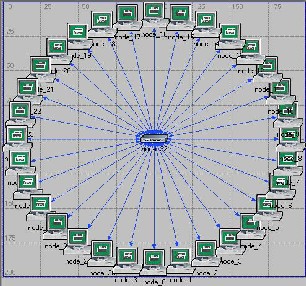
Figure 2: Scenario of Token ring
Here we have a Tr_32_hub_adv in the centre with 32 tr_stations connected through hub with duplex 10 links. This whole network lies in a campus or office. It supports all the requisite or default applications. We have fixed Token Hold- ing Time (THT) to be 0.01 seconds. We have analysed the delay and MAC access time for various packet sizes for both balanced and unbalanced traffic to get the optimum or most effective packet size and to compare its results for both bal- anced and unbalanced traffic.
IJSER © 2011 http://www.ijser.org
International Journal of Scientific & Engineering Research Volume 2, Issue 6, June-2011 3
ISSN 2229-5518
The parameters dealt at each work station are shown in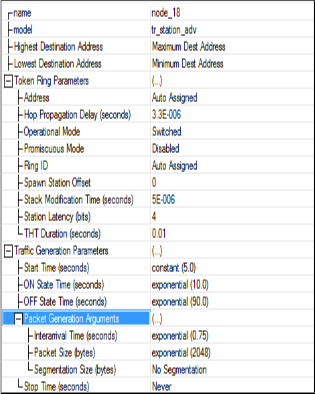
Figure 3 below.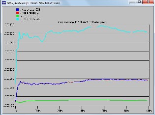
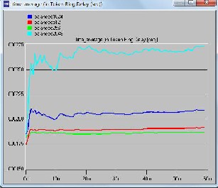
Figure 4: Delay for different packet sizes for balanced load
Figure 3: Workstation Parameters
We have used switched mode operational mode along with THT of 0.01 seconds. For balanced node we have the same inter arrival time for all nodes whereas it’s different for different nodes in case of unbalanced load or traffic.
We have plotted graphs for delay encountered by packet from source to destination and MAC access delay for bal- anced and unbalanced traffic or load for different packet sizes. We have taken four values of packet sizes i.e.256,
512, 1024 and 2048 bytes.
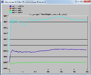
Figure 4 and 6 are for balanced traffic or load. The former is for delay encountered by packets from node to destination and the later one is for media access delay for nodes. Figure
5 and 7 are for unbalanced traffic or load. The former is for delay encountered by packets from node to destination and the later one is for media access delay for nodes. Figure 8 and 9 compare the total delay and delay associated with me- dia access for balanced and unbalanced load at different packet sizes.
Figure 5: Delay for different packet sizes for unbalanced load
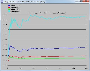
Figure 6: Media access delay for different packet sizes for balanced load
IJSER © 2011 http://www.ijser.org
International Journal of Scientific & Engineering Research Volume 2, Issue 6, June-2011 4
ISSN 2229-5518
Token Ring is Local Area Network technology based on token access method where a node can send data only if it has token and transmission is just for time interval equal to Token Holding Time. Here we can have both balanced and unbalanced loads which enable it to support most of the real time applications but to ensure that the delays associated should be low. That in turn depends on packet size. For a given number of nodes packet size needs to be optimized as delay and throughput depends on it too. Here on analysing the result we can say that 256 bytes of packet size is opti- mum for balanced traffic or load and for unbalanced one we can choose 256 or 512 as delays are same for both. On com- paring total delay encountered by packets and media access delay between balanced and unbalanced load, the former one has lower values of delays associated than the later one.
Figure 7: Media access delay for different packet sizes for unbalanced load
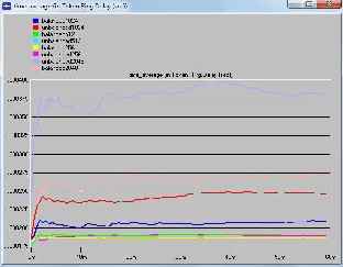
Figure 8: Delay for different packet sizes for balanced and unbalanced load
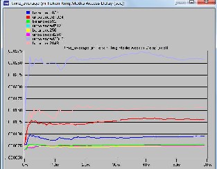
Figure 9: Delay for different packet sizes for balanced and unbalanced load
1. Werner Bux, Felix H. Closs, C. Kuemmerle, H. J.Keller, and H.
R.Mueller,”Architecture and Design of a Reliable Token-Ring Network,” lEEE Journal on Selected Areas in communications, Vol. SAC-I, No. 5, pp. 756-765, November 1983.
2. ANSVIEEE Std.802.2-1985,”Logical Link Control,”1985.
3. ANSVIEEE Std.802.5-1985,”Token Ring Access Method and
Physical Layer Specifications,” 1985.
4. Bux, W.,” Token-ring local-area networks and their perfor- mance“ , Proceedings of the IEEE, Feb 1989.
5. Smythe, C. ,” ISO 8802/5 token ring local-area networks”, Elec-
tronics & Communication Engineering Journal 1999.
6. Nasro Min-Allah, Manzoor Elahi, Xing jiansheng, Wang Yong- ji,” Enhancing Feasibility Analysis of IEEE 802.5 Token Ring”,
IEEE 2008.
IJSER © 2011 http://www.ijser.org