International Journal of Scientific & Engineering Research, Volume 2, Issue 2, February-2011 1
ISSN 2229-5518
Optimized AES Rijndael implementation on embedded controller R8C
R.Elumalai1, Dr.A.R.Reddy2
1Vinayaka Mission University, Salem, Tamil Nadu, India
elumalai.e pcet@gmail.com
2Madanapalli Institute of Technology and Science, Madanapalli, Andhra Pradesh.
ar_reddy@yahoo.com
Abstract— Advanced Encryption Standard (AES) Rijndael algorithm has gained popularity as it is deployed in various embedded systems. Realization of AES algorithm on microcontroller with minimum memory will be useful for deploying it in low cost applications. R8C microcontroller from Renesas is one of the popular microcontrollers in industrial application, being low cost and versatile processor having all peripherals like three UART, three timers, SSU, I2C, LIN, USB, 10 channels ADC with operating frequency at 20MHz. This paper discusses the implementation of AES on R8C controller its speed and memory requirement for the same.
Index Terms—R8C microcontroller, AES Rijndael, optimization.
—————————— • ——————————
1 INTRODUCTION
Microcontroller can be used in a wide range of applica- tions, such as industrial control, monitoring, communica- tion interface in wireless sensor network for environment monitoring and battle field ad-hoc network [1]. The 8/16 bit microcontroller with their limited ability in computa- tion and power, the security is the one of the most impor- tant issue for these applications. With limited computa- tional ability the cryptography algorithm when imple- mented not only consumes CPU time but also the pre- cious memory area both program and data memory. The AES Rijndael algorithm is one algorithm which can be implemented on all types of microprocessor because of its basic design flexibility in block, key size and number of rounds. Rijndael’s internal round structure has instruc- tion-level parallelism and hence implementing on hard- ware is very easy [1, 2].
1.1 WHAT IS RIJNDAEL?
AES is a block cipher developed to address the threatened key size of Data Encryption Standard (DES). AES- Rijndael was developed by Joan Daemen and Vincent Rijmen, Rijndael [4, 5] and was selected from five finalists namely; 1. Mars Developed by the IBM team that devel- oped Lucifer; 2. RC6 Developed by the RSA Laboratories;
3. Rijndael Developed by Joan Daemon and Vincent Rij- men; 4. Serpent Developed by Ross Anderson, Eli Biham, and Lars Knudsen; 5. Two fish Developed by Counter- pane Systems (upon the parameters such as security, per- formance, efficiency, flexibility, and implementability) by NIST as the Advanced Encryption Standard (AES) replac- ing DES and published as FIPS 197 in November 2001 [5]. It is a symmetric block cipher that can process 128 bits
message blocks and 128, 192, and 256 bits key lengths. Both hardware and software implementation of AES- Rijndael are more attractive.
Following is the convention used to describe the opera- tions in this paper.
• Nb: input block length divided by 32
• Nk : key length divided by 32
• Nr : number of rounds
• State : the intermediate cipher result
• Sub state: 8 bit, divided unit of state, if block length is 128-bit, it has 16 sub state of 8-bit
• GF: finite field, Galois field
| Block size in words Nb | Key length in words Nk | Number of round Nr |
128-bits key | 4 | 4 | 10 |
192-bits key | 4 | 6 | 12 |
256-bits key | 4 | 8 | 14 |
Table1. Number of key bits v/s number of round
The block length of plain message is 128 bits divided by
32 results in 4 words and key length can be extended by
multiples of 32 bits. Moreover the operation is based on 8
bits size of sub state, which gives 8/16 bit processor the
highest advantage to implement it by writing algorithm
IJSER © 2011 http://www.ijser.org
International Journal of Scientific & Engineering Research, Volume 2, Issue 2, February-2011 2
ISSN 2229-5518
in both assembly and high level langue. The AES algo- rithm basically consists of four byte oriented transforma- tion for encryption and inverse transformation for de- cryption process namely [1],
a) Byte substitution using substitution box table. (S-box):
b) Shifting rows of the state array using (Row transforma- tion)
c) Mixing the data within each column of the state array. (Mixing columns)
d) Adding a round key to the state. (Add round key)
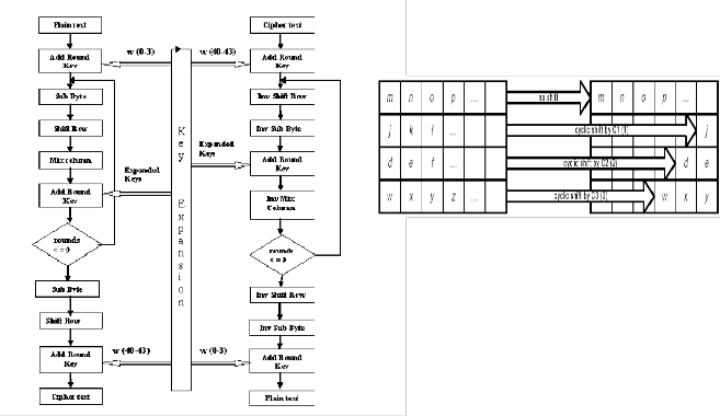
Encryption Decryption Figure 1 Structure of AES Rijndael algorithm
The figure 1 shows AES Rijndael Encryption and Decryp- tion structure, where plain text input to the encryption and cipher text input to the decryption algorithm is 128 bit block. The key provided is expanded into an array of forty - four 32bit words, w[i]. Four distinct words forming
128 bits serve as a key for each round in both encryption and decryption. In encryption process first four words w(0 – 3) are used as key in the first round but for decryp- tion last four words w(40 – 43) are used in the first round.
1.2 BASIC OPERATION OF AES RIJNDAEL
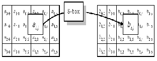
1.21 Byte sub operation
The ByteSub transformation is a non-linear operation which takes 8-bit sub state as its input and produce same size next sub state. The output is predetermined value defined at S-box which takes 16 by 16 byte of memory [1].
1.22 ShiftRow operation
In ShiftRow, the rows of the State are cyclically shifted over different offsets. Row 0 is not shifted; Row 1 is shifted over C1 bytes, row 2 over C2 bytes and row 3 over C3 bytes. The ShiftRow transformation is individual to every last 3 rows of the state. Each of the three rows
shifts by all different bits which decided by block length
[1].
Fig3. ShiftRow operation
1.23 MixColumn operation
In MixColumn, the columns of the State are con- sidered as polynomials over GF (28) and multiplied mod- ulo x4 + 1 with a fixed polynomial c(x) [1]. The MixCo- lumn transformation operates independently on every column of the state and treats each sub state of the col-
umn as term of a(x) in the equation b(x)=c(x)® a(x), where c(x)= ‘03’X3+’01’X2+’01’X+’02’.This polynomial is coprime to (X4 + 1) For example, in the fig4. a(x) is
a0,jX3+ai,jX2+a2,jX+a3,j and it is used as multiplicand of op- eration.
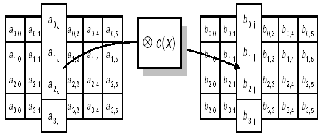
Fig4. MixColumn operation
1.24 AddRoundKey operation
The AddRoundKey operation is simply a bitwise EXOR of roundkey and state. The Round Key is derived from the Cipher Key by means of the key schedule. The Round Key length is equal to the block length Nb. The figure 5 shows Add round key operation.
Fig2. Sub Byte operation
IJSER © 2011 http://www.ijser.org
International Journal of Scientific & Engineering Research, Volume 2, Issue 2, February-2011 3
ISSN 2229-5518
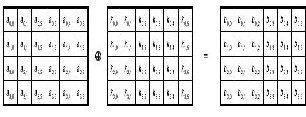
Fig5. AddRoundKey operation
2 RELATED WORK
Rijndael can also be implemented very efficiently on a wide range of processors and in hardware. Rafael R. Sevilla implemented by 80186 assembly and Geoffrey keating’s Motorola 6805 implementation is also available on Rijndael site [3]. During the evaluation process the all five finalist algorithms were evaluated for the hardware implementation including 8 bit processor 8051. Number of works has been published in this regard by various people. R8C micro controller an industrial standard pro- cessor was not used for AES Rijndael implementation. This paper discusses implementation of AES with opti- mized memory without compromising on speed of the system.
3 IMPLEMENTATION
3.1 Renesas R8C Controller
The R8C/Tiny Series of single-chip microcomputers was developed for embedded applications by Renesas. The R8C/Tiny Series supports instructions tailored for the C language, with frequently used instructions imple- mented in one-byte op-code. It thus allows development of efficient programs with reduced memory requirements when using either assembly language or C. Furthermore, some instructions can be executed in a single clock cycle, enabling fast arithmetic processing.
R8C has features like CPU core operating at 20MHz, on chip ROM,RAM, and data Flash memories, program- mable I/O ports, 9 interrupts with 7 priority levels, 14 bit watch dog timer, 3 timers, 4 UARTs, synchronous com- munication port, I2C bus, LIN module, USB, 10 channel 10 bit ADC and 2 comparators which makes it most pre- ferred industrial application microcontroller.
For implementation on R8C microcontroller, Renesas High performance Embedded workshop V.4.07.01 with simulator version 4.1.04.00 which is provided by Renesas was chosen for convenience. It provides integrated devel- opment environment composed of compiler and simula- tor also. Every cycle number and code size output de- pends on embedded workshop. Every design decision is tradeoff between speed and code size.
3.2 ByteSub operation
Byte substitution can be done in the two different
ways. First, taking the multiplicative inverse in GF (28) and ‘00’ is mapped onto itself. Then, applying an affine (over GF(2)) transformation defined by 8 by 8 matrix, produces the output. This approach needs sacrificing of speed because of several numbers of extra operations. Whereas the other way using S-box gains speed but loses the code size for storing S-box on the memory. In this implementation S-box approach was chosen.
3.3 MixColumn operation
MixColumn operation needs a certain number of multiplication operations on GF (28). Every finite field multiplication can be done using tables, Logs and Antilog tables. Like ByteSub operation, using table need more memory space while increasing speed. Especially, in MixColumn operation, multiplicand is confined as ‘01’,
‘02’, and ‘03’, which means ‘01’ and ‘02’ multiplication can provide the clue for ‘03’ multiplication. Therefore to exploit this special feature, direct multiplication approach was chosen instead of using tables.
3.4 Storing state
Repeated round comprises 4 different transformation. Each transformation need state as its input and produce output as new state. Such data transaction between each state and register executed very frequently. Also for arithmetic and logic operation the operand, each sub state should stay at register. Therefore the storing state issue is very critical. If the state stays at memory it is easier to fetch each 8-bit sub state from memory to register with indirect address register A0 and A1. However this ap- proach need more cycle consumption because from/to memory to/from register transaction need 2 cycles each, which is twice as much as from/to register to/from regis- ter scheme. If all sub state can be stored at registers, the memory will be referenced only for round key and S-box, which is impossible to be stored at registers.
4. SIMULATION RESULT
Code was run on the Renesas High performance em- bedded workshop V.4.07.01 with simulator version
4.1.04.00 with test vector from Brian Gladman’s technical paper [5]. The implementation was optimized many times. From many versions of implementation, two simu- lation results are proposed depending on the storing state issue. The one stores the state at memory and the other at registers.
Table2. Simulation result of memory version
IJSER © 2011 http://www.ijser.org
International Journal of Scientific & Engineering Research, Volume 2, Issue 2, February-2011 4
ISSN 2229-5518
The total number includes consideration of the number of rounds. In this implementation, the block and key length are 128-bit each. Therefore 10 rounds constitute one en- cryption procedure. In the 10 rounds of encryption pro- cedure, precomputation is executed just once which gives weight factor 1, and other modules have all different ex- ecution times as in Cycle column of the Table2. Whereas, code length weight factor is irrelevant with cycle number weight factor because some modules are reused every time while the other modules are not. For example, Ad- dRoudKey module executed at round0, round1-9 and round10 but MixColumn executed only at round1-9, which makes the different code weight factor 3 and 1 re- spectively.
Module | Cycle | Code (Byte) |
Precomputation | 1 | 1 |
ByteSub | 10 | 2 |
ShiftRow | 10 | 2 |
MixColumn | 9 | 1 |
AddRoundKey | 11 | 3 |
branch | 1 | 1 |
Table2. Weight factor of each module
With weight factor total number of cycle and code are computed by equation below.
Total cycle number =
I: Cycle number( i ) * weight factor( i )
Total code size =
I: Code number( i ) * weight factor( i )
Where i is every module
The round0-10 number is pure execution number, which excluding precomputation feature. Because precomputa- tion is composed of S-box input to memory, key input to memory, key expansion and data block input, these phas- es happens just once in the whole life time of sensors. Once done precomputation can be reused afterward if there is no key update and S-box update. For data block input, it can be assumed as initially staying at special function register, beforehand.
The Table3 shows much improved result after storing state at registers. The improvement is 44% and 41.9% in the cycle number and code size respectively.
Table3. Simulation result of Register version
5. EVALUATION
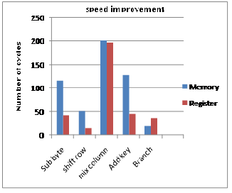
The fully registered implementation produced re- markably improved output as at table4 and table5. Tri- vially increased time consumption at branch module stems from complicated register assignment scheduling. This sacrifice makes utilization percent of register nearly full, which means most of the data transactions happen between register and register. The MixColumn module is still takes much part of cycle number. This module is also the critical part for register scheduling because it need four multiplication with four different sub state at the same time while keeping their initial state. Therefore indi- rect address registers was used temporarily for normal operations. For other modules the utilization of register is slightly over 50%, which gives more possibility to im- prove the efficiency. Table5 shows size improvement after storing state in the register.
Table4. Speed improvement by register
Module | Cycle | Code (Byte) |
Precomputation | 2178 | 1649 |
ByteSub | 42 | 56 |
ShiftRow | 15 | 28 |
MixColumn | 196 | 96 |
AddRoundKey | 45 | 60 |
branch | 36 | 10 |
Total | 5863 | 1552 |
(round0-10) | 2615 | 329 |
IJSER © 2011 http://www.ijser.org
International Journal of Scientific & Engineering Research, Volume 2, Issue 2, February-2011 5
ISSN 2229-5518
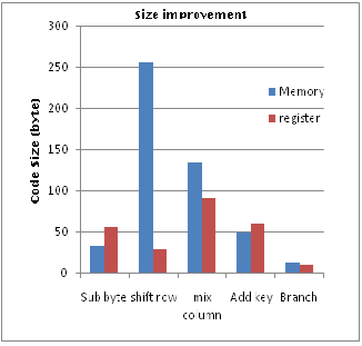
Table5. Size improvement by register
Comparing with other implementations the output is ob-
viously better. The Table6 and 7 are from Rijndael pro-
posal [1] and they show execution time and code size of
other implementation depending on key and block
length.
REFERENCES
[1] Daemen and V. Rijmen, AES Proposal: Rijndael
(Version 2). NIST AES
[2] NIST, Advanced Encryption Standard (AES), (FIP
PUB 197), November 26, 2001
[3] Baker.W.“Introduction to analysis of Data Encryp-
tion Standard”, Laguna Hills CA; Aegean park press,
1991
[4] “cryptography and Network security principles
and practices” by William Stallings, Eastern economy
edition publication 4th edition 2006
[5] A Specification for Rijndael, the AES Algorithm
v3.3, Brian Gladman, May 2002
[6] www.esat.kuleuven.ac.be/~rijmen/rijndel/ Rijn-
dael home site
[7] A.J. Elbert, E. Yip, B. Chetwynd, C. Paar: “An FPGA
Implementation and Performance Evaluation of the
AES Block Cipher Candidate Algorithm Finalists”,
IEEE Transactions on VLSI, August 2001, vol. 9, no. 4,
pp. 545-557.
[8] A Communications Security Architecture and
Cryptographic Mechanisms for Distributed Sensor
Networks DARPA SensIT Workshop, Oct 8, 1999
[9] Helion Technologies. High Performance (Rijndael)
cores, 2001. Amphion Semiconductor. CS5210-40:
High Performance AES Encryption Cores, 2001
Key/Block length | Number of cycles | Code length |
(128, 128) a) | 4065 cycles | 768 byte |
(128, 128) b) | 3744 cycles | 826 byte |
(128, 128) c) | 3168 cycles | 1016 byte |
(192, 128) | 4512 cycles | 1125 byte |
(256, 128) | 5221 cycles | 1041 byte |
Table6. Execution time and code size Rijndael in Intel
8051 assembler
In case of Intel 8051 assembler, as code size increase, the speed decreases, this improvement in speed while sacri- ficing size can be also done at AVR microcontroller by executing multiplication by tables.
Key/Block length | Number of cycles | Code length |
(128, 128) a) | 8390 cycles | 919 byte |
(192, 128) | 10780 cycles | 1170 byte |
(256, 128) | 12490 cycles | 1135 byte |
Table7. Execution time and code size Rijndael in Motorola
68HC08 assembler
6 CONCLUSION
Rijndael implementation using registers for storing state improves the efficiency over 40% in both speed and code size. Hence implementation using register will be more optimal when the processor is less loaded with oth- er works which not only increases the speed but also re- duces memory usage.
IJSER © 2011 http://www.ijser.org