International Journal of Scientific & Engineering Research Volume 3, Issue 12, December-2012 1
ISSN 2229-5518
Optimization of Tools for CNC Machine: An
Explication & An Overview
N.S. Pohokar, L.B.Bhuyar,
Abstract— Over the last few decades, the range of engineering materials encountered in machine shops has increased greatly, as has the variety of cutting tools that are capable of machining these materials. Recent advances in computer hardware and software technology have led to research in calculation of efficient cutting parameters and design and development of a tool or combination of tools for a specific operation or set of operations. In this paper an attempt is made to review the literature on optimizing machining parameters and geometric parameters in CNC machine. Various conventional techniques employed for machining optimization include geometric programming, geometric plus linear programming, goal programming, sequential unconstrained minimization technique, dynamic programming etc. The latest techniques for optimization include fuzzy logic, scatter search technique, genetic algorithm, Taguchi technique and response surface methodology. This paper gives the machine tool methodology optimization.
Index Terms— CNC, Machining optimization, goal programming, fuzzy logic, genetic algorithms, Taguchi technique, response surface methodology.
1 INTRODUCTION
—————————— • ——————————
S the tool life & tool wear is a major problem faced by the industry, it has long been recognized that conditions during cutting, such as feed rate, cutting speedand depth
of cut, should be selected to optimize the economics of ma- chining operations, as assessed by productivity, total manufac- turing cost per component or some other suitable criterion. Taylor [1] showed that an optimum or economic cutting speed exists which could maximize material removal rate. Manufac- turing industries have long depended on the skill and expe- rience of shop-floor machine-tool operators for optimal selec- tion of cutting conditions and cutting tools. Considerable ef- forts are still in progress on the use of handbook- based con- servative cutting conditions and cutting tool selection at the process planning level. The most adverse effect of such a not- very scientifc practice is decreased productivity due to sub- optimal use of machining capability. The need for selecting and implementing optimal machining conditions and the most suitable cutting tool has been felt over the last few decades. Despite Taylor’s early work on establishing optimum cutting speeds in single pass turnings, progress has been slow since all the process parameters need to be optimized. Furthermore, for realistic solutions, the many constraints met in practice, such as low machine tool power, torque, force limits and compo- nent surface roughness, must be over come.The non- availability of the required technological performance equa- tion represents a major obstacle to implementation of opti- mized cutting conditions in practice. This follows since extensive testing is required to establish empirical perfor- mance equations for each tool coating–work material combi- nation for a given machining operation, which can be quite
————————————————
• Nilesh S. Pohokar is currently pursuing Ph.D degree program in mechani- cal engineering in Amravati University, India, PH-07212530158 E-mail: nilesh.pohokar@gmail.com
• Lalit B. Bhuyar has completed Ph.D in Mechanical engineering in Amravati University,Worked as a Head of Mechanical Engineering De- partment Prof. Ram Meghe Institute of Technology and Research Badnera, India, PH-072126811246. E-mail: lbbhuyar@gmail.com
expensive when a wide spectrum of machining operations is considered. Further the performance equations have to be up- dated as new coatings, new work materials and new cutting tools are introduced. While comprehensive sets of equations are found in some Chinese and Russian handbooks [8],[20] as well in the American handbook [3] and Kroneberg’s textbook [9] most authors have not included discussions on the more modern tools, new work materials and tool coat-
ings. Diffculties are experienced in locating the empirical per- formance equations for moderntool designs because these are hidden under computerized databases in proprietary software [18] as noted in recent investigations “[45],[46]”.
Recent works are concentrated on design and development of tool, milling operations for determining machining parame- ters. The optimization strategy for single pass end milling on CNC machine tools, allowing for many practical constraints has been based on minimum production time per component. Different optimization procedures have been developed using new approaches such as genetic algorithm (GA), hill climbing algorithm and memetic algorithm to optimize machining pa- rameters for milling operations.
Modeling and simulation of machining processes is a criti-
cal step in the realization of high quality machined parts. To
precisely simulate the machining operations, accurate models
of cutting tools used in the machining processes are required.
In metal cutting industry, an end mill cutter plays an impor-
tant role for obtaining the desired shape and size of a compo-
nent. A variety of helical end mill cutters are used in the in-
dustry. Helical cylindrical, helical ball, taper helical ball, bull-
nosed and special purpose end mills are widely used in aero-
space, automotive and die machining industries. The analysis
of the geometry of the tool surfaces and cutting flutes along
with the cutting forces acting on the end mill plays an impor- tant part in the design of the end mill and the quality of the manufacturing process. Traditionally, the geometry of cutting tools has been defined using the principles of projective geo-
metry. The advancements in the domain of Computer Aided Design (CAD) allow a designer to specify the cutting tool sur- faces in terms of biparametric surface patches. Using such an
IJSER © 2012 http://www.ijser.org
International Journal of Scientific & Engineering Research Volume 3, Issue 12, December-2012 2
ISSN 2229-5518
approach, one may develop the comprehensive three- dimensional (3D) surface based definitions of the cutting tools.
Hu Gong [61] describes an optimized positioning procedure for flank milling ruled surfaces with cylindrical cutter. The proposition that the envelope surface of cylindrical cutter is the offset surface of tool axis trajectory surface is proved using ki- nematics approach. It is a complement of Bedi’s [53] analysis about the envelope surface of cylindrical cutter.
Optimization procedures based on the genetic algo- rithm, hill climbing algorithm and memetic algorithm were demonstrated for the optimization of machining parameters for milling operation developed by basker et al [62]. They describe development and utilization of an optimization system, which determines optimum machining parameters for milling opera- tions like face milling, corner milling, pocket milling and slot milling.
Sheen et al [63] developed an effective method for identify- ing machining features. It reliably determines the shapes be- tween top and bottom profiles of workpiece. Most of the iso- lated, intersecting or 2.5D or 3D features can be recognized. Fur- thermore, the merging of the slot, step and notch features simpl- ifies the manufacturing sequence and minimizes burr produced by discontinuous machining. Using the information of machin- ing features, the manufacturing sequence can be automatically arranged and different kinds of tool paths can be efficiently generated.
A geometric approach to the problem of multi-patch machin- ing by generating bisectors to partition the region into smaller sub regions, and generates the toolpath by offsetting the sub region boundary by using a special offset function was intro- duced by Li [64]. The author developed this approach for gene- rating a boundary conformed toolpath for free-form multi-patch surface machining.
Saffar et al. [65] develops a 3D simulation system which is employed in order to predict cutting forces and tool deflection during end-milling operation. In order to verify the accuracy of
3D simulation, results (cutting forces and tool deflection) were compared with those based on the theoretical relationships may be attributed to the followings:
(1) Material properties in the simulations are defined based on the Johnson–Cook theory, i.e. they are a function of strain, strain rate, and workpiece temperature whereas in the theoreti- cal relationships, properties are simply defined using the con- stant material coefficient.
(2) In simulation, non-linear geometric boundaries such as the free surface of the chip can be represented and used while theoretical relationships are based on linear geometric bounda- ries.
2 REVIEW OF LITURATURE
2.1 Conventional Optimization Technique
The follwing are some convetional optimization technique suggested by the concern researchers. Gilbert [2] studied the optimization of machining parameters in turning with respect to maximum production rate and minimum production cost as criteria. Armarego & Brown [10] investigated unconstrained machine-parameter optimization using differential calcu-
lus. Brewer & Rueda [6] carried out simplifed optimum anal- ysis for non-ferrous materials. For cast iron (CI) and steels, they employed the criterion of reducing the machining
cost to a minimum. A number of nomograms were worked out to facilitate the practical determination of the most eco- nomic machining conditions. They pointed out that the more- diffcult-to-machine materials have a restricted range of para- meters over which machining can be carried out and thus any attempt at optimizing their costs is artifcial. Brewer [8] sug- gested the use of Lagrangian multipliers for optimization of the constrained problem of unit cost, with cutting power as the main constraint. Bhattacharya et al [11] optimized the unit cost for turning, subject to the constraints of surface roughness and cutting power by the use of Lagrange’s method. Walvekar
& Lambert [12] discussed the use of geometric programming to selection of machining variables. They optimized cutting speed and feed rate to yield minimum production cost. Petro- poulos [13] investigated optimal selection of machining rate variables, viz. cutting speed and feed rate, by geometric pro- gramming. A constrained unit cost problem in turning was optimized by machining SAE 1045 steel with a cemented car- bide tool of ISO P-10 grade. Sundaram [16] applied a goal- programming technique in metal cutting for selecting levels of machining parameters in a fne turning operation on AISI 4140 steel using cemented tungsten carbide tools. Ermer & Kromo- diharajo [19] developed a multi-step mathematical model to solve a constrained multi-pass machining problem. They con- cluded that in some cases with certain constant total depths of cut, multi-pass machining was more economical than single- pass machining, if depth of cut for each pass was properly allocated. They used high speed steel (HSS) cutting tools to machine carbon steel. Hinduja et al [21] described a procedure to calculate the optimum cutting conditions for turning opera- tions with minimum cost or maximum production rate as the objective function. For a given combination of tool and work material, the search for the optimum was confned to a feed rate versus depth-of-cut plane defned by the chip-breaking constraint. Some of the other constraints considered include power available, work holding, surface fnish and dimensional accuracy. Tsai [25] studied the relationship between the multi- pass machining and single-pass machining. He presented the concept of a break-even point, i.e. there is always a point, a certain value of depth of cut, at which single-pass and double- pass machining are equally effective. When the depth of cut drops below the break-even point, the single-pass is more economical than the double-pass, and when the depth of cut rises above this break-even point, double-pass is better. Car- bide tools are used to turn the carbon steel work material. Go- palakrishnan & Khayyal [37] described the design and devel- opment of an analytical tool for the selection of machine pa- rameters in turning. Geometric programming was used as the basic methodology to determine values for feed rate and cut- ting speed that minimize the total cost of machining SAE 1045 steel with cemented carbide tools of ISO P-10 grade. Surface fnish and machine power were taken as the constraints while optimizing cutting speed and feed rate for a given depth of cut. Agapiou [38] formulated single-pass and multi-pass ma- chining operations. Production cost and total time were taken
IJSER © 2012 http://www.ijser.org
International Journal of Scientific & Engineering Research Volume 3, Issue 12, December-2012 3
ISSN 2229-5518
as objectives and a weighting factor was assigned to prioritize the two objectives in the objective function. He optimized the number of passes, depth of cut, cutting speed and feed rate in his model, through a multi-stage solution process called dy- namic programming. Several physical constraints were consi- dered and applied in his model. In his solution methodology, every cutting pass is independent of the previous pass, hence the optimality for each pass is not reached simultaneously. Prasad [43] reported the development of an optimization module for determining process parameters for turning opera- tions as part of a PC-based generative CAPP system. The work piece materials considered in their study include steels, cast iron, aluminium, copper and brass. HSS and carbide tool ma- terials are considered in this study. The minimization of pro- duction time is taken as the basis for formulating the objective function. The constraints considered in this study include power, surface fnish, tolerance, work piece rigidity, range of cutting speed, maximum and minimum depths of cut and to- tal depth of cut. Improved mathematical models are formu- lated by modifying the tolerance and work piece rigidity con- straints for multi-pass turning operations. The formulated models are solved by the combination of geometric and linear programming techniques.
2.2 Current Techniques
The latest techniques for optimization include fuzzy logic, scatter search technique, genetic algorithm, Taguchi technique and response surface methodology.
2.2.1 Fuzzy Logic
Fuzzy logic has great capability to capture human
commonsense reasoning, decision-making and other aspects of human cognition. Kosko [42] shows that it overcomes the limitations of classic logical systems, which impose inherent restrictions on representation of imprecise concepts. Vague-
ness in the coeffcients and constraints may be naturally mod- elled by fuzzy logic. Modelling by fuzzy logic opens up a new way to optimize cutting conditions and also tool selection.
Methodology: As per Klir & Yuan [44] fuzzy logic involves a fuzzy interference engine and a fuzzifcation-defuzzifcation module. Fuzzifcation expresses the input variables in the form of fuzzy membership values based on various member- ship functions. Governing rules in linguistic form, such as if cutting force is high and machining time is high, then tool wear is high, are formulated on the basis of experimental ob- servations. Based on each rule,inference can be drawn on out- put grade and membership value. Inferences obtained from various rules are combined to arrive at a fnal decision. The membership values thus obtained are defuzzifed using vari- ous techniques to obtain true value, say of flank wear.
2.2.2 Genetic algorithm (GA)
These are the algorithms based on mechanics of natu-
ral selection and natural genetics, which are more robust and
more likely to locate global optimum. It is because of this fea-
ture that GA goes through solution space starting from a group of points and not from a single point. The cutting condi-
tions are encoded as genes by binary encoding to apply GA in optimization of machining parameters. A set of genes is com- bined together to form chromosomes, used to perform the ba- sic mechanisms in GA, such as crossover and mutation. Cros- sover is the operation to exchange some part of two chromo- somes to generate new offspring, which is important when exploring the whole search space rapidly. Mutation is applied after crossover to provide a small randomness to the new chromosomes. To evaluate each individual or chromosome, the encoded cutting conditions are decoded from the chromo- somes and are used to predict machining performance meas- ures. Fitness or objective function is a function needed in the optimization process and selection of next generation in genet- ic algorithm. Optimum results of cutting conditions are ob- tained by comparison of values of objective functions among all individuals after a number of iterations. Besides weighting factors and constraints, suitable parameters of GA are re- quired to operate effciently. GA optimization methodology is based on machining performance predictions models devel- oped from a comprehensive system of theoretical analysis, experimental database and numerical methods. The GA pa- rameters along with relevant objective functions and set of machining performance constraints are imposed on GA opti- mization methodology to provide optimum cutting condi- tions.
Implementation of GA: First of all, the variables are encoded as n-bit binary numbers assigned in a row as chromosome strings. To implement constraints in GA, penalties are given to individuals out of constraint. If an individual is out of con- straint, its ftness will be assigned as zero. Because individuals are selected to mate according to ftness value, zero ftness individuals will not become parents. Thus most individuals in the next generation are ensured in feasible regions bounded by constraints. The GA is initialized by randomly selecting individuals in the full range of variables. Individuals are se- lected to be parents of the next generation according to their ftness value. The larger the ftness value, the greater their possibility of being selected as parents. Wang & Jawahir [58] have used this technique for optimization of milling machine parameters. Kuo & Yen [50] have used a genetic algorithm based parameter tuning algorithm for multidimensional mo- tion control of a computer numerical control machine tool.
2.2.3 Scatter Search Technique (SS)
This technique originates from strategies for combining
decision rules and surrogate constraints. SS is completely ge-
neralized and problem-independent since it has no restrictive
assumptions about objective function, parameter set and con- straint set. It can be easily modifed to optimize machining operation under various economic criteria and numerous practical constraints. It can obtain near-optimal solutions with-
in reasonable execution time on PC. Potentially, it can be ex- tended as an on-line quality control strategy for optimizing machining parameters based on signals from sensors. Chen & Chen [51] have done extensive work on this technique. Methodology: First of all, machining models are required to determine the optimum machining parameters including cut-
IJSER © 2012 http://www.ijser.org
International Journal of Scientific & Engineering Research Volume 3, Issue 12, December-2012 4
ISSN 2229-5518
ting speed, feed rate and depth of cut, in order to minimize
unit production cost. Unit production cost can be divided into
four basic cost elements:
• Cutting cost by actual cut in time
• Machine idle cost due to loading and unloading oper-
ation and idling tool motion cost
• Tool replacement cost
• Tool cost
For the optimization of unit production cost, practical con-
straints which present the state of machining processes need
to be considered. The constraints imposed during machining
operations are:
• Parameter constraint – Ranges of cutting speed, feed rate and depth of cut
• Tool life constraint – Allowable values of flank wear width and crater wear depth
• Operating constraint – Maximum allowable cutting force, power available on machine tool and surface fnish requirement.
An optimization model for multi-pass turning operation can be formulated. The multi-pass turning model is a con- strained nonlinear programming problem with multiple va- riables (machining variables). The initial solution for SS is picked in a random way. The user-specifed parameters have to be given. The experimentation can be run on a PC with Pen- tium800Mhzprocessor. The computational results validate the advantage of SS in terms of solution quality and computation- al requirement.
2.2.4 Taguchi technique
Genichi Taguchi is a Japanese engineer who has been active
in the improvement of Japan’s industrial products and
processes since the late 1940s. He has developed both the phi-
losophy and methodology for process or product quality im-
provement that depends heavily on statistical concepts and
tools, especially statistically designed experiments. Many Jap-
anese frms have achieved great success by applying his me- thods. Sullivan [35] reports that Taguchi has received some of Japan’s most prestigious awards for quality achievement, in- cluding the Deming prize. In 1986, Taguchi received the most
prestigious prize from the International Technology Institute – The Willard F. Rockwell Medal for Excellence in Technology. Taguchi’s major contribution has involved combining engi- neering and statistical methods to achieve rapid improve- ments in cost and quality by optimizing product design and manufacturing processes.
Barker [31] reported that since 1983, after Taguchi’s associa- tion with the top companies and institutes in USA (AT & T Bell Laboratories, Xerox, Lawrence Institute of Technology (LIT), Ford Motor Company etc.), his methods have been called a radical approach to quality, experimental design and engineering. Sullivan [35] reported that the term “Taguchime- thods” (TM) refers to the parameter design, tolerance design, quality loss function, on-line quality control, design of expe- riments using orthogonal arrays, and methodology applied to evaluate measuring systems.Pignatiello [29] identifes two separate aspects of the Taguchi methods: the strategy of Tagu- chi and the tactics of Taguchi. Taguchi tactics refer to the col-
lection of specifc methods and techniques used by Genichi Taguchi, and Taguchi strategy is the conceptual framework or structure for planning a product or process design experiment. Benton [36] reported that Taguchi addresses design and engi- neering (off-line) as well as manufacturing (on-line) quality. This fundamentally differentiates TM from statistical process control (SPC), which is purely an on-line quality control me- thod. Taguchi’s ideas can be distilled into two fundamental concepts:
(a) Quality losses must be defned as deviations from targets, not conformance to arbitrary
specifcations [36].
(b) Achieving high system-quality levels economically re- quires quality to be designed into the product. Quality is de- signed, not manufactured, into the product “[28],[30]"
Chanin [34] stated that Taguchi methods represent a new philosophy. Quality is measured by the deviation of a func- tional characteristic from its target value. Noises (uncontrolled variables) can cause such deviations resulting in loss of quali- ty. Taguchi methods seek to remove the effect of noises.
Taguchi [30] described that quality engineering encom- passes all stages of product/process development: system design, parameter design, and tolerance design. Byrne & Ta- guchi [27], however, pointed out that the key element for achieving high quality and low cost is parameter design. Through parameter design, levels of product and process fac- tors are determined, such that the product’s functional charac- teristics are optimized and the effect of noise factors is mini- mized. Kackar & Shoemaker [23] observed that parameter de- sign reduces performance variation by reducing the influence of the sources of variation rather than by controlling them, it is thus a very cost-effective technique for improving engineering design.
Applications: Chanin [30] remarked that Japanese compa- nies such as Nippon Denso, NEC, and Fugitsu have become world economic competitors by using Taguchi’s approach which has potential for saving experimental time and cost on product or process development, as well as quality improve- ment. Kacker & Shoemaker [23], Phadke [24], pointed out that the methodology advocated by Taguchi has been applied within AT & T to a variety of problems ranging from IC fabri- cation to response time opti-mization of a UNIX system since Taguchi’s frst visit to AT & T Bell Laboratories in 1980. Ghosh [32] remarked that Taguchi’s ideas are also being used in many others US companies such as Ford and Xerox. There are also many courses on robust parameter design offered by or- ganizations like American Supplier Institute, Rochester Insti- tute of Technology, and the Center for Quality and Productivi- ty Improvement at the University of Wisconsin in Madison. The American Supplier Institute also has an annual sympo- sium where case studies on the application of the Taguchi Me- thods are presented.
The Casting Division of Ford Motors has been one of the pioneers in training employees in Taguchi’s methods since
1983. In a few case studies conducted in the Casting Division of Ford Motors and illustrated the depth and impact on the product quality and productivity that has occurred since the
IJSER © 2012 http://www.ijser.org
International Journal of Scientific & Engineering Research Volume 3, Issue 12, December-2012 5
ISSN 2229-5518
decision to implement Taguchi’s approach was made. Mo- neymaker & Hubbard [26] have presented a case of the appli- cation of loss function concept to the quality improvement program at the Rockwell International Steel Foundry at Atchi- son, Kansas. Lin & Kackar [22] have shown how a 36-run or- thogonal array design was used to improve a wave soldering process by studying 17 variables simultaneously. Kamat & Rao [41] have presented a case study of Taguchi optimization related to manufacturing processes for die-cast components. The use of optimal parame-ter combinations obtained from the analysis reduced the rejection of die-cast components by 90%. Tsui [25] presented robust design optimization for multiple characteristic problems. Robust design improves product or manufacturing process design by making the output response insensitive (robust) to diffcult-to-control variations. The mul- tivariate quality loss function considered by Pignatiello [40] has been extended to include the smaller and the larger-the- better type characteristics. Under various assumptions, ap- propriate two-step procedures were developed that minimize the average multivariate loss. The proposed two-step proce- dure substantially reduces the dimension of the design opti- mization problem and allows for future changes of response target values without re-optimization. The proposed proce- dure was illustrated with a polysilicon deposition example. Singh & Kumar [52] have applied Taguchi’s technique for op- timizing surface fnish, tool wear, cutting force and power consumed in turning operations for machining En24 steel with titanium carbide-coated tungsten carbide inserts. The success of many applications has demonstrated the power of Tagu- chi’s overall approach. It is also worth mentioning that many of the specifc statistical techniques he has proposed for im- plementing robust parameter design have generated a great deal of controversy. However, most commentators agree that Taguchi’s loss function concept represents a solid contribu- tion. Furthermore, there is general agreement that off-line ex- periments during the product or process design stage are of great value and the methodology is based on solid engineer- ing principles. Reducing quality loss by designing the prod- ucts and processes to be insensitive to variations in noise va- riables is a novel concept to statisticians and quality engineers.
2.2.5 Response surface methodology (RSM)
Experimentation and making inferences are the twin fea-
tures of general scientifc methodol-ogy. Statistics as a
scientifc discipline is mainly designed to achieve these objec-
tives. Planning of experiments is particularly very useful in
deriving clear and accurate conclusions from the experimental
observations, on the basis of which inferences can be made in
the best possible manner. The methodology for making infe- rences has three main aspects. First, it establishes methods for drawing inferences from observations when these are not ex- act but subject to variation, because inferences are not exact
but probabilistic in nature. Second, it specifes methods for collection of data appropriately, so that assumptions for the application of appropriate statistical methods to them are satisfed. Lastly, techniques for proper interpretation of results are devised.
The advantages of design of experiments as reported by
Adler [15] and Johnston [7] are as follows. (1) Numbers of trials are reduced.
(2) Optimum values of parameters can be determined. (3) Assessment of experimental error can be made.
(4) Qualitative estimation of parameters can be made.
(5) Inference regarding the effect of parameters on the chac-
teristics of the process can be made.
Cochran & Cox [5] quoted Box [4] as having proposed re-
sponse surface methodology for the optimization of experi-
ments. In many experimental situations, it is possible to
represent independent factors in quantitative form. Then these
factors can be thought of as having a functional relationship or
response:
Y = cp(X1, X2, . . . , Xk ) ± er ,
between the response Y and X1, X2, . . . Xk of k quantitative factors. The function cp is called response surface or response
function. The residual er measures the experimental error. For a given set of independent variables, a characteristic surface responds. When the mathematical form of cp is not known, it can be approximated satisfactorily within the experimental region by a polynomial. The higher the degree of the poly- nomial the better is the correlation, though at the same time the costs of experimentation become higher. The methodology may be applied for developing the mathematical models in the form of multiple regression equations correlating the depen- dent parameters such as cutting force, power consumption, surface roughness, tool life etc. with three independent para- meters, viz. cutting speed, feed rate and depth of cut, in a turning process. In applying the response surface methodolo- gy, the dependent parameter is viewed as a surface to which a mathematical model is ftted. For the development of regres- sion equations related to various quality characteristics of turned parts, the second-order response surface may be as- sumed as:
This assumed surface Y contains linear, squared and cross- product terms of variables Xi ’s. In order to estimate the re- gression coeffcients a number of experimental design tech- niques are available. Box & Hunter [4] have proposed that the scheme based on central composite rotatable design fts the second-order response surfaces very accurately. Lambert & Taraman [14] developed an adequate mathematical model for the cutting force acting on a carbide tool while machining SAE
1018 cold-rolled steel in a turning operation and then utilized the model in the selection of the levels of the machining va- riables of cutting speed, feed rate, and depth of cut, such that the rate of metal-removal could be at the highest possible val- ue without violating some given force restriction. By using response surface methodology the three independent va- riables (cutting speed, feed rate and depth of cut) could be investigated simultaneously to study their effects on the cut- ting force, resulting in considerable saving in time and money over traditional methods of analysis. Taraman [14] investi- gated multi-machining output multi-independent variable
IJSER © 2012 http://www.ijser.org
International Journal of Scientific & Engineering Research Volume 3, Issue 12, December-2012 6
ISSN 2229-5518
turning research by response surface methodology. The pur- pose of this research was to develop a methodology that would allow determination of the cutting conditions (cutting
TABLE 1

SUMMARY OF OPTIMIZATION TECHNIQUES.

Technique Tool used References Remarks
speed, feed rate and depth of cut) such that the specifed crite- rion for each of several machining-dependent parameters (sur-
Lan- grange,s
method
Langrange’s multiplier Brewer
[8],Bhatacharya
[11]
Used for constrained optimization
face fnish, tool force and tool life) could be achieved simulta-
neously. To accomplish this, frst mathematical models were
developed representing the relationship between the depen-
dent and independent variables of the process. A central com-
posite design was used to develop the models in order to mi-
nimize the amount of experimentation. The models were
represented by response surfaces and contours of these sur-
faces were obtained at different levels of each of the indepen-
Geometric program- ming
Theory based on the arithmetic inequality
Walve- kar & Lam- bert,pet ropou- luos
,Gopalk rishnan
&
khayyal
Opimization technique developed for solving a class of nonlinear opti- mization problem found in engineering design and manufacturing
dent variables in planes of the other independent variables. By superimposing the contours, a proper combination of the cut- ting speed, feed rate and depth of cut can be selected to satisfy some specifed criteria. Disposable inserts of tungsten carbide were used to turn SAE1018 cold-rolled steel. Hassan & Suli- man [33] presented mathematical models for the prediction of surface roughness, tool vibration, power consumption and cutting time, when turning medium carbon steel using tungsten carbide tools under dry conditions. The functional relationships of these variables and the machining-
Goal
program- ming
Form of multi- objective optimiza- tion
Goal programming
combines the logic of
optimization in ma-
thematical
programming with the decision maker’s desire to satisfy several goals
A collection of algorithms used to compute
optimal policies
given a perfect model
of environment
Sundaram Form of multi-objective
optimization
Agapiou Solving sequential or multi-stage decision problems
by solving a series of single variable problems
independent variables (cutting speed, feed rate and depth of
cut) were established by a second-order polynomial multi- regression analysis. The surface roughness model developed was used as an objective function to establish the optimum cutting conditions while the tool vibration level, power con-
sumption and cutting time were considered the functional constraints. El Baradie [39] presented a study of the develop- ment of a surface roughness model for turning grey cast iron (154 BHN) using tipped carbide tools under dry conditions and for a constant depth of cut (d = 1.00 mm). The mathemati- cal model utilizing the response surface methodology was developed in terms of cutting speed, feed rate and nose radius of the cutting tool. These variables were investigated using design of experiments and utilization of the response surface methodology. The turning operation was performed on a 10 h.p. lathe. The work pieces were cast in the form of cylindrical bars 200 mm in diameter and approximately 500 mm in length. The cutting tests were carried out using a tungsten carbide insert (grade K10). Surface roughness measurements were made using a Taylor–Hobson Surtronic surface rough-
Fuzzy logic
Genetic algorithm
Taguchi technique
Response surface methodol- ogy
Fuzzy interface engine
& fuzzification–
defuzzification module
A CGI (common gateway interface) program
Design of experiments, Orthogonal arrays, ANOVA,MINITAB.15
Design expert software
(DX6)
Kosko (1997); Klir &
Yuan (1998)
Kuo (2002); Wang
(2004)
Pignatiello
(1993);
Tsui (1999); Singh & Kumar (2003,
2004,
2005) Taraman (1974); Hassan & Suliman (1990); Bara- die
(1993); Noor-
din
Based on a machining model which works on human common-sense reasoning, decisionmak- ing
and other concepts
of human cognition
Based on a machining
model developed from
theoretical analysis, experimental database and numerical methods Based on actual experimental work and determination of opti- mum
conditions using
statistical tools
Based on a machining model developed by mathematical and statistical techniques
ness measuring instrument. A frst-order model covering the cutting speed range of 110–350 m/min and a second-order model covering the cutting speed range of 80–495 m/min are presented in this study. Contours of the surface roughness outputs were obtained in planes containing two of the inde- pendent variables. These contours were further developed to select the proper combination of the cutting speed and feed rate to increase the metal removal rate without sacrifcing the quality of the surface roughness produced.
Table 1 summarizes the traditional and latest optimization techniques discussed in 2.1 and 2.2 for the optimization of process variables in metal machining.
(2004)
3 METHODOLOGY
The main effort are taken as the study of machining parameter like speed, depth of cut and feed rate etc. Also the tool geometry (Rake angle) and design a milling tool for rough milling operation. Development of a relational model to pre- dict the tool life based on machining and geometric parameter by Buckingham’s rr-theorem. Design of experiment is perform with help of Taguchi method and combination of selected pa- rameters using analysis of variance. Experimental reading are taken form a VMC milling machine. The analysis of theoretical and experimental is perform for the effect of tool life estima- tion. Before The figure 1 showing method applied to optimize the milling tool of a CNC machine.
IJSER © 2012 http://www.ijser.org
International Journal of Scientific & Engineering Research Volume 3, Issue 12, December-2012 7
ISSN 2229-5518
Study of all geometric and machining Parame- ters of CNC milling machine and machine tools
Development of relational model of machining, geometry parameters and Tool Life of a milling tool
Generate Mathematical Model w.r.t. dependent and Inde- pendent variable
Apply response surface methodology Based on a machining model devel- oped by mathematical and statistical techniques
Design of experiment with the help of Taguchi Method and combination
Formulate the Mathematical model for calculating theoretical tool life
Experimentation sug- gested by Taguchi and AN VA Techniques
Development of Genetic algorithm Based on a machining model developed from theoret- ical analysis and experimental database
Analysis of theoretical and Experimental Data
Optimization of geometric and machining parameters and predicting the tool life
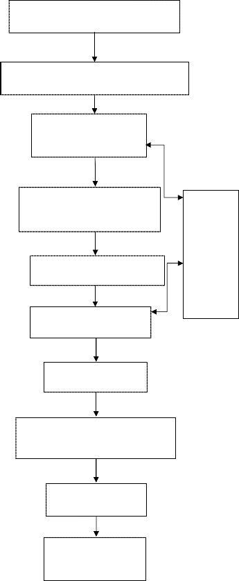
Fig 1. Flowchart Showing Methodology
Applying various parameter range ac- cording to the tool data book and data availa- ble at vari- ous hand book
4 CONCLUSION
The critical review of the literature suggested that in- adequate work is done w. r. t. operation time, accuracy, tool life, tool path planning etc. Many researchers are engaged in the study of the shape change, feed rate control and optimize cutting speed in terms of the tool life, tool path generation algorithm of the milling operations. The Maximum effects of the insert run out errors and variation of the feed rate on the surface roughness and dimensional accuracy in face milling operations using surface roughness model, where the optimal feed rate and maximum metal removal rate are determined. Based on the above literature survey the proposed study is focus to design, development & performance optimization of tool for milling operation in CNC.
As the tool life & tool wear is a major problem faced by the industry, it is therefore proposed in the present study that, it gives the direction of development of unified represen- tation schemes that can provide direct 3D models for down- stream technological applications and this work not only im- proves the profit rate but also the production cost and produc- tion time.
Generation of algorithm for tool path planning helps to improve the critical shape milling operations and solves the problem of positioning of the work piece. This generalized tool safety software helps to increase the tool life. Also this work may lead to improvement of quality of tool and the tool path planning for milling CNC.
REFERENCES
[1] F W Taylor,” On the art of cutting metals,” Trans. ASME 28: pp. 31–35, 1907 [2] W W Gilbert. “Economics of machining. In Machining – Theory and prac-
tice,” Am. Soc. Met.pp.476–480, 1950
[3] ASME ,” Research committee on metal cutting data and bibliography,” Ma- nual on cutting of metalswith single point tools, 2nd edn, 1952
[4] G E P Box, J S,” Hunter Multifactor experimental Design” J. Ann. Math. Stat. pp.28, 1957
[5] G Cochran, G M Cox,1 Experimental design (New Delhi: Asia Publishing
House),1962
[6] R C Brewer, R Rueda “A simplifed approach to the optimum selection of machining parameters”Eng. Dig. 24(9): pp.133–150, 1963
[7] R E Johnston, “Statistical methods in foundry expts” AFS Trans. 72: pp.13–24,
1964
[8] R C Brewer, Parameter Selection Problem in Machining. Ann. CIRP 14: pp.11,
1966
[9] M Kroneberg “Theory and practice for operation and development of ma- chining process” (Oxford:Pergamon), 1966
[10] E J A Armarego, R H Brown,The machining of metals (Englewood Cliffs, NJ: Prentice Hall),1969
[11] A Bhattacharya, R Faria-Gonzalez, H Inyong, “Regression analysis for pre- dicting surface fnish and its application in the determination of optimum machining conditions,” Trans. Am. Soc. Mech.Eng. 92: pp.711, 1970
[12] B K Lambert, K Taraman “Development and utilization of a mathematical model of a turning Operation,” Int. J. Prod. Res. 11: pp.69–81, 1973
[13] P G Petropoulos “Optimal selection of machining rate variable by geometric
programming,”Int. J. Prod. Res. 11: pp.305–314, 1973
[14] K Taraman “Multi-machining output-multi independent variable turning
IJSER © 2012 http://www.ijser.org
International Journal of Scientific & Engineering Research Volume 3, Issue 12, December-2012 8
ISSN 2229-5518
research by response surface methodology,” Int. J. Prod. Res. 12: pp.232–245,
1974
[15] Y P Adler, E V Markova, Y V Granovsky “The design of experiments to fnd optimal conditions”(Moscow: Mir Publishers), 1975
[16] R M Sundaram “An application of goal programming technique in metal cutting” Int. J. Prod.
[17] Res. 16: pp.375–382, 1978
[18] A B Sandvik “Coroplan process planning software and coroplan user ma- nual, Sandvik Automation,” GmbH, 1981
[19] D S Ermer, S Kromordihardjo “Optimization of multi-pass turning with constraints” J. Eng. Ind.103: pp.462–468, 1981
[20] X Ai, S Xiao “Metal cutting condition handbook “(China: Mechanics Industry
Press), 1985
[21] S Hinduja, D J Petty, M Tester, G “Barrow Calculation of optimum cutting conditions for turning Operations,” Proc. Inst. Mech. Eng. 199(B2): pp.81–92,
1985
[22] K M Lin, R N Kackar “Wave soldering optimization by orthogonal array design method” Electricalpackaging and production pp.108–115, 1985
[23] R N Kackar, A C Shoemaker, “Robust design: A cost effective method for improving manufacturing processes,” AT & T Tech. J. 65(Mar–Apr): pp.39–
50, 1986
[24] M S Phadke,”Design optimization case studies,” AT&T Tech. J. 65(Mar–Apr):
pp.51–84, 1986
[25] P.Tsai ”An optimization algorithm and economic analysis for a constrained machining model.”PhD thesis, West Virginia University, 1986
[26] D R Moneymaker, A R Hubbard “ Loss function techniques as applied to
steel foundry processes,”AFS Trans. 95: pp.755–756, 1987
[27] D M Byrne, S Taguchi The Taguchi approach to parameter design. Quality
Progress 20: pp.19–26, 1987
[28] D Daetz The effect of product design on product quality and product cost.
Quality Progress20(6): pp.54–61, 1987
[29] J J Pignatiello “An overview of the strategy and tactics of Taguchi” Inst. Ind.
Eng. Trans. 20:pp.247–254, 1988
[30] G Taguchi “Quality engineering in production systems “(New York: McGraw-Hill), 1989
[31] T B Barker Engineering quality by design (New York: Marcel Dekker), 1990 [32] S Ghosh Statistical design and analysis of industrial experiments (New York:
Marcel Dekker), 1990
[33] G A Hassan, S M A Suliman, “Experimental modeling and optimization of turning medium carbon Steel,” Int. J. Prod. Res. 28:pp. 1057–1065, 1990
[34] M N Chanin, C.H.Kuei, C Lin, “Using Taguchi design, regression analysis and simulation to study maintenance float systems,” Int. J. Prod. Res. 28: pp.1939–1953, 1990
[35] K H Paul, L P Sullivan, G Taguchi, “Using Taguchi methods in quality engi- neering,” Quality Progress pp.55–59, 1990
[36] W C Benton, “Statistical process control and the Taguchi method: A compar- ative evaluation”Int. J. Prod. Res. 29: pp. 1761–1770, 1991
[37] B Gopalakrishnan, F A Khayyal “Machine parameter selection for turning with constraints: An analytical approach based on geometric programming,” Int. J. Prod. Res. 29: pp. 1897–1908, 1991
[38] J S Agapiou, “The optimization of machining operations based on a com- bined criterion, Part 1: The use of combined objectives in single-pass opera- tions, Part 2: Multi-pass operations”. J. Eng.Ind., Trans. ASME 114, pp. 500–
513, 1992
[39] M. El Baradie, “Surface roughness model for turning grey cast iron (154
BHN),” Proc. Inst.Mech. Eng. 207: pp. 43–50, 1993
[40] J J Pignatiello, “Strategies for robust multi-response quality engineering” Inst.
Ind. Eng. Trans.25: 5–25, 1993
[41] Y V Kamat, M V Rao, “A Taguchi optimization of the manufacturing process for die cast components. Proc. 6th AIMTDR Conference, Bangalore, pp. 174–
179, 1994
[42] B Kosko “Neural network and fuzzy systems – A dynamic approach to machine intelligence”(New Delhi: Prentice Hall of India), 1997
[43] S R K Prasad, P N Rao, U R K Rao “Optimal selection of process parameters for turningoperations in a CAPP system,” Int. J. Prod. Res. 35: pp. 1495–1522,
1997
[44] G J Klir, B Yuan “Fuzzy system and fuzzy logic – theory and practice “(En- glewood Cliffs, NJ:Prentice Hall), 1998
[45] E J A Armarego, D Ostafev , “A study of a proprietary computerized tech- nological machining performance database,”. 8th Int. Manufacturing Confe- rence, pp. 26–33, 1998
[46] D. Ostafev ,“ Multiple constraint optimization analysis and software for
selecting machining condition on rough turning operation”. Ph D thesis, Uni- versity of Melbourne, Melbourne, Australia, 1999
[47] WY Bao, I N Tansel., “Modeling micro-end-milling operations. Part I: analyti- cal cutting force model. Journal of Machine Tools & Manufacture “ 40: pp.2155–2173, 2000
[48] W Y Bao, I N Tansel, “Modeling micro-end-milling operations. Part II: tool run-out. Journal of Machine Tools & Manufacture” 40: pp..2175-2192, 2000
[49] [W Y Bao, I N Tansel, “Modeling micro-end-milling operations. Part III: influ- ence of tool wear. Journal of Machine Tools & Manufacture” 40: pp. 2193-
2211, 2000
[50] L Y Kuo, J Y Yen “A genetic algorithm based parameter-tuning algorithm for multi dimensional motion control of a computer numerical control machine tool,” Proc. Inst. Mech. Eng. B 216: 2002
[51] M Chen, K Y Chen “Determination of optimum machining conditions using scatter search,” New optimization techniques in engineering, pp. 681–697,
2003
[52] H Singh, P Kumar “Quality optimization of turned parts (En24 steel) by
Taguchi method,” Product.J. 44: pp. 43–49, 2003
[53] S Bedi, S Mann, C Menzel,”.Flank milling with flat end cutter. Journal of com- puter aided design” 35: pp.293–300, 2003
[54] Z Yin., “Rough and finish tool-path generation for NC machining of freeform surfaces based on a multiresolution method. Journal of computer aided de- sign” 36: pp.1231–1239, 2004
[55] M Y Noordin “Application of response surface methodology in describing
the performance of coated carbide tools when turning AISI 1045 steel,” J. Ma- ter. Process Technol. 145: pp.46–58, 2004
[56] Singh H, Kumar P,” A Tool wear optimization in turning operation by Tagu- chi method,”Indian J. Eng. Mater. Sci. 11: pp. 19–24, 2004
[57] H Singh, P B Kumar,” Effect on power consumption for turned parts using
Taguchi technique,”Product. J. 45: pp. 231–238, 2004
[58] X Wang, I S Jawahir, “Web based optimization of milling operations for the selection of cutting conditions using genetic algorithms,” Proc. Inst. Mech. Eng. 218: 212–223, 2004
[59] H Singh, P Kumar, “Optimizing cutting force for turned parts using Taguchi’s parameter design Approach,” Indian J. Eng. Mater. Sci. 12: pp. 97–103, 2005
[60] S P Radzevich, “A cutting-tool-dependent approach for partitioning of sculp-
tured surface,” Journal of computer aided design, 37: pp. 767–778, 2005
[61] A. Aggarwal, H.Singh, “Optimization of machining techniques – A retrospec- tive and literature review,”J Indian Journal sadhana, 30: pp. 699–711, 2005
[62] H Gong, LX Cao, J Liu, “Improved positioning of cylindrical cutter for flank milling ruled surfaces”, Journal of computer aided design, 37: pp. 1205–1213,
2005
[63] N Baskar, P Asokan, R Saravanan., G Prabhaharan, “Selection of optimal machining parameters for multi-tool milling operations using a memetic al-
IJSER © 2012 http://www.ijser.org
International Journal of Scientific & Engineering Research Volume 3, Issue 12, December-2012 9
ISSN 2229-5518
gorithm”, Journal of Materials Processing Technology, 174: pp.239–249, 2006 [64] B T Sheen, C F You, “Machining feature recognition and tool-path generation
for 3-axis CNC milling”, Journal of computer aided design, 38: pp. 553–562,
2006
[65] C L Li, “A geometric approach to boundary-conformed toolpath generation”, Journal of computer aided design 39: pp.941–952, 2007
[66] R J Saffar, M R Razfar,Zarei E O,Ghassemieh,,” Simulation of three-dimension cutting force and tool deflection in the end milling operation based on finite
element method” Journal of Simulation Modelling Practice and Theory,16:
pp.1677–1688,2008
[67] J H Kim, J W Park, T J Ko, End mill design and machining via cutting simula- tion”. Journal of computer aided design 40: pp.324–333,2008
[68] P Tandon, M R Khan, “Three dimensional modeling and finite element simu- lation of a generic end mill”, Journal of computer aided design, 41: pp.106–
114, 2009
[69] H C Kim, S H Lee, D Y Yang, “Toolpath planning algorithm for the ablation process using energy sources. Journal of computer aided design”,41:pp.59–64,
2009
________________________________________________________________________________________________________________________________
IJSER © 2012 http://www.ijser.org