International Journal of Scientific & Engineering Research, Volume 4, Issue 8, August-2013
ISSN 2229-5518
1686
Optimization and Enhancement of Load
Carrying Capacity of CNC Coordinate Drilling
Machine using Finite Element Method
N. Ashwin Kumar1, Basava Raju Pondhe2
1(B.Tech in Mechanical with Specialization in Energy Engineering, VIT University,Vellore, India)
2(Joint General Manager, HMT Machine Tools Limited, Bangalore, India)
Abstract— The CNC Co-Ordinate Drilling machine indigenously designed and manufactured by HMT Machine Tools Ltd is capable of withstanding a load carrying capacity of 8000 kg. In order to meet the demand for the same machine with a higher load carrying capacity of 14000 kg the CNC Co- Ordinate Drilling machine was modified. The objective of this industrial project is to carry out analysis and to validate the actual load carrying capac- ity of the original design of machine bed and the new design proposed by the company, using finite element analysis. As a part of analysis for this project an optimized design of the bed was suggested by the author to endure the load carrying capacity of 14000 kg. Analysis was carried out on the bed of the machine where additional ribs were added to the bed in order to withstand higher capacity. The software’s used include Solid Works premium 2012 for modeling and ANSYS 14.5 to carry out finite element analysis. Three stages of FEA were carried out, that is for the original bed and the bed redesigned by the company followed by the optimized bed designed by the author. The optimized design generated during the project
is also capable of withstanding 14000 kg by reorientation of the ribbing pattern at appropriate locations. Resulting in reduction of weight by 800 kg and approximately a sum of INR 100000 rupees can be saved.
—————————— ——————————
The CNC Coordinate drilling machine is a bridge type double column with a moving arm designed for drilling, tapping, milling, and rough boring operations. It is ideally suited for heavy and bulky components and tube sheet drilling. The machine consists of bed, column, spindle head, table assembly and electrical components. The salient features of this machine includes large work area, linear motion anti friction guide ways for table slider for X axis whereas hardened and ground guide ways coated with Turcite facilitate the motion along Y and Z ax- is and preloaded precision ball screw for X, Y, Z, W axis. The CNC system is empowered with AC Servo motors which facilitate the movements about the 4 axis. Apart from having power tool clamping, the spindle is support- ed on a set of precision angular contact ball bearings.
Coordinate drilling machines are intensively used for machining purpose in tool rooms. The operations such as drilling, tapping, milling and rough boring are the pri- mary operations used to carry out machining in the indus- trial sector. Reducing the weight of such machine would make it easier for transportation, maintenance also reduce the cost of manufacturing of the machine.
The first set of analysis was carried out on the bed originally designed by the company to withstand a load carrying capacity of 8000 kg; the original bed is des- ignated as BED1.0. The second analysis was carried out on the bed redesigned by the company for a load capacity of
14000 kg this bed is designated as BED 2.0. The third set of analysis was carried out on the optimized bed designed by the author. The optimized bed designed by the author is designated as BED 3.0.
2.1 Material Properties
The bed is made by assembling Mild Steel plates of various thicknesses by the process of welding. For all the 3 beds namely BED 1.0, 2.0, 3.0 the same material is used. The properties of Mild Steel are mentioned in table 1. The steel used complies with the HMT standards. The compo- sition, scope, applications, and requirements of the mate- rial complies with IS 2062:2006, IS 1852:1985 standards.
Table 1: Physical Properties of mild steel
Analysis plays a major role in optimization. To enhance the load carrying capacity of this machine, modi- fications were carried out in the bed, work table and the ball screw of the machine. The major structural modifica- tions were carried out in the machine bed which was cre- ated by welding Mild Steel plates together. The reorienta- tion of the ribbing pattern led to the increase in the load carrying capacity. Three stages of finite element analysis were carried out in the course of the project.
.
1
IJSER © 2013
http://www.ijser.org
International Journal of Scientific & Engineering Research, Volume 4, Issue 8, August-2013
ISSN 2229-5518
1687
Optimization and Enhancement of Load Carrying Capacity of CNC Coordinate Drilling Machine using Finite Element Method
2.2 BED 1.0
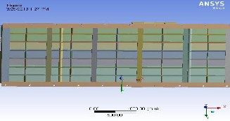
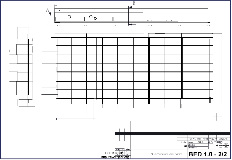
The original bed designed by HMT initially to with- stand a load carrying capacity of 8000 kg is designated as BED 1.0 this bed is made by welding Mild Steel plates of varying thickness in a criss-cross pattern. 23 types of Mild steel plates are used to create the original bed. The weight of BED 1.0 sums up to 11000 kg. Drawing-1 & 2 represents the Solid Works drawing of BED 1.0 in the 2D format. The ge- ometry of BED 1.0 is shown in fig 1.
Fig 1: Geometry of BED 1.0
2.3 BED 2.0
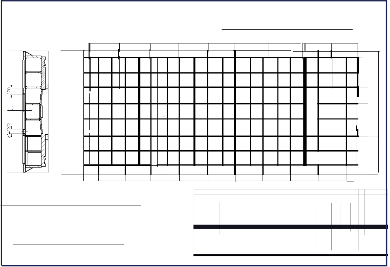
The BED 1.0 re-designed by HMT in order to withstand a higher load carrying capacity of 14000 kg is designated as BED 2.0. This bed is made by welding addi- tional 4 new types of Mild Steel plates to the Original BED
1.0. The 4 new plates created are used to form additional ribs and hence enhance the strength of the structure. The new plates are placed in between the old ribs. Another sa- lient feature about this design is that it has another set of leveling screws along with foundation bolts which are aligned on either sides of the central axis of the machine. By introducing an additional set of leveling screws which are attached to 40 mm thick plates the equilibrium and support of the structure increases to a great extent. The additional ribs added weigh 1107 kg. Hence the overall weight of BED 2.0 is 12107 kg. Drawing 3 represents the Solid Works drawing of BED 2.0 in the 2D format. The ge- ometry of BED 2.0 is shown in fig 2.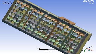
Fig 2: Geometry of BED 2.0
2
2.4 BED 3.0
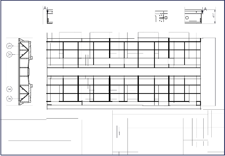
The optimized design of bed is also designed to withstand a load carrying capacity of 14000 kg is desig- nated as BED 3.0. This bed is made by welding an addi- tional 2 new Mild Steel plates of varying thickness to the Original BED 1.0. The concept of purlin structure is intro- duced in this design which enhances high load carrying capacity with a limited quantity of material used.
The additional ribs added to the BED 1.0 accounts only to 320 kg and the overall weight of BED 3.0 is 11320 kg which saves up to 787 kg of Mild Steel over BED 2.0. Due to the concept of Purlin structure a considerable amount of weight is reduced for the same required effect. Drawing 4 represents the Solid Works drawing of BED 3.0 in the 2D format. The geometry of BED 3.0 is shown in fig
3.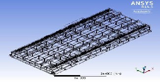
Fig 3: Geometry of BED 3.0 (wire mesh view)
2.4.1 Concept of Purlins
The principal function of roofing purlins is to transfer the forces on the roof of a building to its main structure. The wall rails perform the same role on the fa- cades. Purlins and wall rails are important components in the secondary structure of a building. It should be noted that, in a large number of steel-frame buildings, with a single ground floor, the weight of the purlins and wall rails constitutes an important element in terms of the overall weight of the structure (15 to 20%); failure to op- timize on this could lead to a deal being lost in a highly competitive situation. The purlin structure of a building is designed in accordance with the type of roofing to be used.
The concept of Purlins is very famous for build- ing’s roof tops. The same Purlin concept of distributing the load to the main structure is applied in order to attain an optimized design without any compromise in the load carrying capacity. By implementing this design the Purlin structure gets a new application in the field of Machine Tool Building.
IJSER © 2013 http://www.ijser.org
International Journal of Scientific & Engineering Research, VolDurnrea4w, Isisnueg8,1August-2013
ISSN 2229-5518 30 984 900 2542 854
0 0
1688
]
?Cf 1265
2 .A -(0 no
0 n II
. . . .
. . . . . . . . ...
3 f; 6
: .: :
9 _.£: 21
G)-----J
0-----i
<0- [3----@
13
21
3 6 : :
! "';. .UD 0 u u 0
5500 14---- K
4 I 5500x2420x497 IMS 1000 k I
Designations &FinalDimensions a I j Weight j Ca sting Number ] Remarks
Item
SECTION B-B lor.,.c diojiA5:Uira
-Uno rOhrlono!«>!
Uo k> tn lilol n
•G.1
· ",..,.',
= "' Alerations Old No Date Name Nea pr ASSY.No.
/OraU"' ....""' ' Designat ion: CNC Co-ordinate Drilling Machine Scale Drawn AS"- N f"'PD
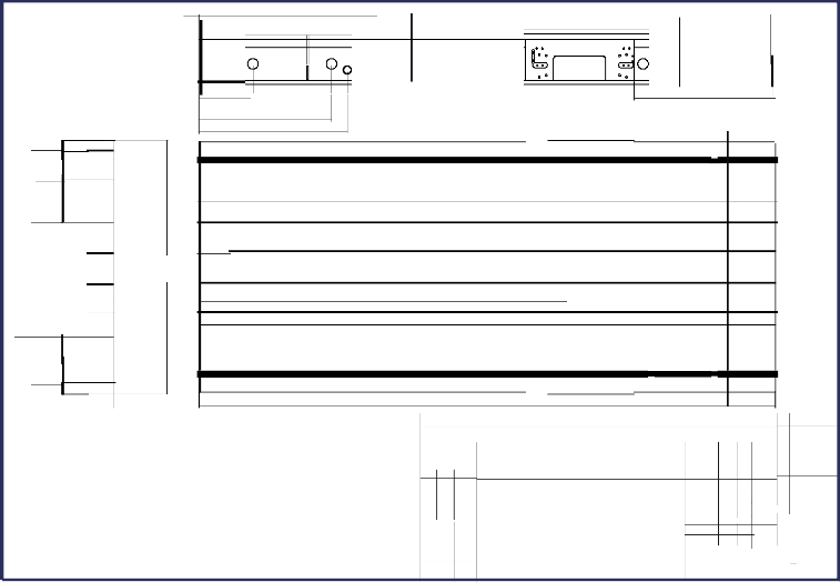
Original Bed (load carrying capacity - 8 Tons) 1:20
BI>Jrbl•ll<
o••,.
" Standards
. -
· ..
All dimensions are in mm
5500
11 do 0 0
497
19 20 20 B 20 20 1 9
"'.--
10 0 0 0 D 0 0 ,'\ I'I 0
"""""'""' 0
D 0 0
f-- "'
0 1 6 ---(0
40 --@ vu --@
k0 v <1 v D <0
@ --@
--(0
--@
s:l
"'
:"
(')
'---'
55 --@ v'-w-l-i'
K0 k0 G
--@ k0 @ --@ ' @ --@
0
"'
"' "'
---® I! "1 1 ---® r® k20 0J
1 6 II r®
(:') r
erJ
"'
---<:V
--@
1'----" '
v-----,
1 6
1'----"
--@ K0 k0
1 20 --@ vu -@ k0
u 0 0 o/ 0 //A 0 u '"
3"1 "5"' 40
0 0 0
574 526 5 6 526 526 526 526 526 526 574
1059
S ECTION B-B
1 41 5
I 5500x2420x497 I MS 10k0g0l I
SECTION A-A
Item I
.
Designations & Final Dirnensions
I Ma terial I Weight Ica sting Numberl
Remarks
lll ,.., •ll3
Alerations
!Osll...,.._,...""' Desjgnat ion: CNC Co-ordinate Drilling Machine
•••,.. Original Bed (load c arrying capacity - 8 Tons )
International Journal of Sc1ent1fic & Engmeenng Research, VolurneD4, rIsasuwe 8i,nAgugu3st-2013
ISSN 2229-5518 d
b,.,,.
0 0
,., ,.,'m
l r l 0 0
683 624 525 561
c D c c D " """""" '""""' c
KB 1\26 '26' K5 B
,\::.:/
{ 1 \:.2:6::: 2
0_, 26
lrf2v6' K r;; lr
'-..
./ \.::'_.., I
r2s' _j '25' w
f----'
_j lr;5' I
"=' '-..
r;?' 24
'-..
./ 1'-J :_, 1'-
IQ IC\ r 2
./ l v 10 '- "
1-u- r2s' '25' h r------,
KB 2;j\ 06 r
'J <:: R 2
kB fib' '26' lo IC\ -@ I
k26) fib' 26 k26' k_2? k26) k26' Il l I §
t) 0 n c: c n Y/,/ / // / / /,( 1.4 0 0 0
SECTION B-B
506 477 554 535 522 522 522 522 526 m_
SECTION A-A
I 5500X2420X497
I MS 112107 k I
Item j Designations&FinaiDirnensions j Materia l ] Weight j ca stingNumber j Remarks
Total weight of BED 2.0 (redesigned by HMT)
Weight of Original Bed 1.0 = 11000 kg
1CID ;:[01 •
12
Alerations Old No. Date Name Neapr ASSY.No.
Weight of additional ribs = 1107 kg
""'u"'-....""' Designation: CNC Co-ordinate Drilling Machine •ll'sca le Drawn [ASH N PD Projection: ®
=.:w.
:D:::
Redesigned by HMT (load canying capacity-14 ton) 1:19 Checked _c:}_ +
TotalweightofBED2.0 =12107kg
"' Standards -c.:.:J
·:· I Alldimensionsare in mm BED 2.0
B
0 0
1 74 823 821 279
B 821 821
160
r"'-' -=-- ---
u
0v u
D U D '""""" " " u " D
r- -
4)
\:.Y r--
-0 rr- K0
I
\?:;
@- f-
/ / / / / / / / / // / / // / / / / / / / // / / // / // // / / //// /// /
I
..,.
"'
-- ---® u 0 1\::2_.-0y
@- f- -
-f- ---<?
SECTION B-B
(24\ (24\
n \:./ f- - \:. /
u u q; D / / / /// //L u D
5500
SECTION A-A
loru c d.i.o.j.Ai....:n-lra
Total weight of BED 3.0 (0ptimized bed design) ...............
Weight of Original Bed 1 .0 = 11000kg
P'> ....,,.,.,
oil.I
lll o!l2
Weight of additional ribs
= 320 kg
'"' o !l
om ow o!l5
= Alerations Old No Da te Name tveapr ASSY.No.
1CDJ 2IDJ •12
/OsliU..--,....,..., De.gnat io n: CNC Co o.dlnate Ddmng Machine rca le Drawn AS !WIN f"i'PD P"JectiOn
..,....Do.u:.,OI.I'I.
E3 +
Total weight of BED 3.0
l.of111'1 of
= 11320 kg ....,.
...,
Optimized Bed (load catryin g capacity • 14 ton) 1:20 Cl1ecke d
Standards
IJSER ., '"' ,.., I All dimensions are i n mm
International Journal of Scientific & Engineering Research, Volume 4, Issue 8, August-2013
ISSN 2229-5518
1690
Optimization and Enhancement of Load Carrying Capacity of CNC Coordinate Drilling Machine using Finite Element Method
Solid Works premium 2012 version is used to create the auto CAD 2D drawings of the beds. These drawings rep- resent the orientation of the ribbing pattern and the as- sembly of plates. The CAD drawings are represented in Drawing 1& 2 (BED 1.0), Drawing 3 (BED 2.0) and Draw- ing 4 (BED 3.0).
4.1 Boundary and Loading Conditions
The boundary and the loading conditions for all 3 beds are the same. This is done in order to attain a clear comparison among the 3 beds. The bounding box geome- try of BED 1.0, 2.0 and 3.0 is 5500 x 2420 x505 mm. The linear motion (LM) guides and the linear motion (LM) blocks are attached to the beds represented in the engi- neering drawings. All the 3 bed have the minimum edge length for the mesh as 0.145990 mm, with a transit ratio of
0.272.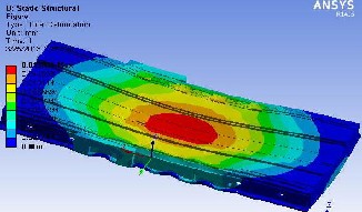
4.2 Finite Element Results of BED 1.0
Fig 5: Total Deformation of BED 1.0
BED 1.0 has 116 bodies with 366078 nodes and
197379 elements. Due to the additional plates added to the original bed design, BED 2.0 has 202 bodies, which hold
409087 nodes and 203145 elements. BED 3.0 has only 153 bodies with 386375 nodes and 198656 elements. The addi- tion of ribs and alteration of ribbing patters causes varia- tion in the bodies, nodes and elements of the beds.
A point load of 14000 kg was equally distributed
on the 8 LM blocks attached to the LM guides as shown in
fig 4. As a result a force of (-) 17161 N/mm was applied on each of the LM block. The degree of freedom was ar- rested in the 10 holes assigned for the foundation bolts. These holes are present in the base plate of the bed. The same loading conditions were applied on all 3 beds. The additional set of leveling screws added to BED 2.0 leaves the degree of freedom arrested for 20 holes in BED 2.0. This gives BED 2.0 additional support in comparison with BED 1.0 and 3.0.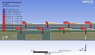
Fig 4: Load Application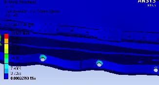
Fig 6: Total Stress of BED 1.0
On applying the load of 14000 kg, BED 1.0 had a maximum deformation of 0.013004 mm. It may be ob- served from fig 5 that the maximum deformation occurred in the center of the bed. From fig 6 we know that the max- imum stress value attained from analysis is 33.527 MPa. The value of maximum stress is well within the yield stress. The new design must incorporate alternating rib- bing pattern to provide support at the point where maxi- mum deformation occurs in order to attain lower defor- mation.
4.3 Finite Element Results of BED 2.0
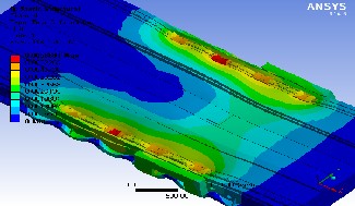
Fig 7: Total Deformation of BED 2.0
3
IJSER © 2013 http://www.ijser.org
International Journal of Scientific & Engineering Research, Volume 4, Issue 8, August-2013
ISSN 2229-5518
1691
Optimization and Enhancement of Load Carrying Capacity of CNC Coordinate Drilling Machine using Finite Element Method
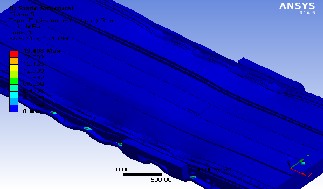
Fig 8: Total Stress of BED 2.0
On applying the load of 14000 kg, BED 2.0 had a maximum deformation of 0.0058803 mm. It may be ob- served from fig 7 that the maximum deformation occurred in the center of the LM blocks where the force was ap- plied. This is a clear indication that there was enough support required to withstand the force. The reorientation of ribbing pattern by adding about 1107 kg to BED 1.0 led to the change in the deformation pattern from that of BED
1.0.
From fig 8 we know that the maximum stress value attained from analysis is 19.48 MPa. The value of
maximum stress is well within the yield stress. This de- sign provides the required support to accomplish very low value of maximum deformation. The maximum stress obtained also is much lesser than that of BED 1.0.
4.4 Finite Element Results of BED 3.0
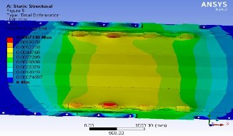
Fig 9: Total Deformation of BED 3.0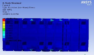
Fig 10: Total Stress of BED 3.0
On applying the load of 14000 kg, BED 3.0 had a maximum deformation of 0.0067138 mm. The deformation pattern observed from fig 9 resembles that of BED 2.0 this is a clear indication that there was enough support re- quired to withstand the applied force. The reorientation of ribbing pattern by adding about 320 kg to BED 1.0 led to the change in the deformation pattern from that of BED
1.0.
From fig 10 we know that the maximum stress value attained from analysis is 14.384 MPa. In this case stress value is 5.11 MPa less than BED 2.0 and well within the yield stress. This design provides the required support to accomplish very low value of maximum deformation. The maximum stress obtained also is much lesser than that of BED 1.0 and BED 2.0.
5.1 Results and Discussions
Table 2: Results of Analysis
From table 2 it is very clear that the maximum de- formation and the maximum stress occurred in BED 1.0. From fig 5 it is evident that the maximum deformation oc- curs at the center of the bed. In order to attain minimum deformation it is important to concentrate in the center re- gion and strengthen it with additional support.
4
IJSER © 2013 http://www.ijser.org
International Journal of Scientific & Engineering Research, Volume 4, Issue 8, August-2013
ISSN 2229-5518
1692
Optimization and Enhancement of Load Carrying Capacity of CNC Coordinate Drilling Machine using Finite Element Method
BED 2.0 is designed in such a way such as to overcome the shortcomings of the former. In this design the deformation is not allowed to concentrate in the center because of the additional ribs added and due to the extra lines of leveling screws added on either sides of the cen- tral axis of the machine. As a result of the modification’s done to the design, there is a considerable reduction in the max deformation and the max stress.
On comparing the results of BED 1.0 and 2.0 it is
becomes obvious that by providing additional support the deformation is prevented from concentrating at the center, hence minimizing the max deformation and stress. The objective of the analysis is to attain the best possible re- sults with the minimum use of material. The intention is to generate a deformation pattern similar to that of BED
2.0. By implementing the concept of purlin principle, the
load is transferred from the LM blocks to the outer struc-
ture of the bed; as a result the required results are ob- tained in BED 3.0.
On considering the results produced by BED 1.0 without the work table and having considering only the static analysis, its maximum deformation is 13 microns and maximum stress is 33.5 MPa whereas the Yield Strength of Mild Steel is 370 MPa. Hence one can conclude that the original bed is capable of withstanding the re- quired load capacity. From the above analysis it is evident that the BED 1.0 is suitable for the prescribed usage of load capacity at lower precision. The maximum allowable deformation for the application of this machine is 20 mi- crons.
one can conclude BED 3.0 will be appropriate if the addi- tional weight is also considered (Work Table) and in meet- ing the required accuracy of deformation i.e. maximum of
20 microns.
The scope of future work can be in three possible ways as giv- en below:
1. Carry out analysis with the work table attached to the bed.
2. Consider the dynamic forces acting on the machine components.
3. Identification of the actual load carrying capability of the individual models of bed.
To accomplish higher precision, minimum de- formation is required. BED 2.0 or BED 3.0 should be cho- sen upon BED 1.0 to obtain a higher precision during its operation. It may be observed that the weight of BED 2.0 is much higher than BED 3.0 on implementing the opti- mized bed design approximately 800 kg of Mild Steel can be saved. Which means a sum of about INR 100000 rupees is saved. Not only BED 3.0 is economically more viable, with respect to operation; its max deformation is almost the same as BED 2.0 and its max stress is around 5 MPa lesser than BED 2.0 consequently during full load condi- tion BED 3.0 is more suitable than BED 2.0.
5.2 Scope of Future Work
The finite element analysis (FEA) has been car- ried out on the bed of the machine. Here, the analysis has considered only the static forces acting on the bed. The dynamic forces have not been taken into consideration. The weight of the work table is 4970 kg an addition of this weight would surely increase the deformation. Hence an analysis is to be carried out with the work table assembled on to the bed as shown in fig 11 for more appropriate re- sults. The 3 models of bed have been analyzed to check/validate if they can withstand required 14000 kg load but their actual capability have not been verified. But
5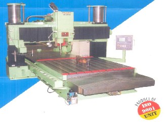
Fig 11: CNC Coordinate drilling machine
[1] Basava Raju Pondhe, P.Balasubramanyam and Anil Kumar P. Katti,
“Finite Element Structural Analysis on CNC Lathe”, part 1– Modelling; NASDYN
98, Finite Element Analysis in Industry-Recent Trends , August 7 1998, IIT Madras.
[2] Basava Raju Pondhe, P.Balasubramanyam and Anil Kumar P. Katti, Finite Element Structural Analysis on CNC Lathe, part 2 – Analysis and design; NASDYN 98, Finite Element Analysis in Industry-Recent Trends , August 7 1998, IIT Madras.
[3] Prof. Dr. Muhsin J. Jweeg, Asst. Prof. Dr. Shawkat J. AL-Tornachi, Asst. Lect. Salah H. Abid-Aun, Optimization of Light Weight Aircraft Wing Structure, Journal of Engineering and Development, Vol. 12, No. 1, March (2008) ISSN 1813-
7822
Books:
[4] Innovent Engineering Solutions, ANSYS Structural Mechanics Training
Manual
[5] Tadeusz Stolarski, Y.Nakasone,S.Yoshimoto, “Engineering Analysis with ANSYS Software”
IJSER © 2013 http://www.ijser.org